R&G ECC0310R User manual

Page 1of 8ECC0310R
R&G Racing
Unit 1, Shelley’s Lane, East Worldham, Alton, Hampshire, GU34 3AQ
Tel: +44 (0)1420 89007 Fax: +44 (0)1420 87301 www.rg-racing.com Email: info@rg-racing.com
FITTING INSTRUCTIONS FOR ECC0310R
LHS ALTERNATOR COVER
HONDA CBR1000RR-R & SP 2020-
THIS KIT CONTAINS THE ITEMS PICTURED AND LABELLED OVER PAGE.
SOME PARTS MAY BE SHOWN FOR CLARITY OF INSTRUCTIONS ONLY.
DO NOT PROCEED UNTIL YOU ARE SURE ALL PARTS ARE PRESENT.
PLEASE READ ALL INSTRUCTIONS BEFORE PROCEEDING.
IF IN ANY DOUBT WHEN FITTING OUR PRODUCTS, CONSULT ONE OF OUR DEALERS
OR HAVE FITTED BY A QUALIFIED TECHNICIAN.
PLEASE NOTE THAT THE WAY THE KIT IS PACKED DOES NOT NECESSARILY REPRESENT THE WAY OF
MOUNTING TO THE BIKE.
IN THE EVENT OF RUBBER WASHERS BEING USED TO HOLD COMPONENTS ONTO BOLTS,
THESE RUBBER WASHERS CAN BE THROWN AWAY.
DIGITAL COPIES OF THESE INSTRUCTIONS ARE AVAILABLE FROM:
WWW.RG-RACING.COM

Page 2of 8ECC0310R
R&G Racing
Unit 1, Shelley’s Lane, East Worldham, Alton, Hampshire, GU34 3AQ
Tel: +44 (0)1420 89007 Fax: +44 (0)1420 87301 www.rg-racing.com Email: info@rg-racing.com
TOOLS REQUIRED
•Set of allen keys to include 3mm, 4mm
& 5mm
•10mm spanner or socket
GENERAL TORQUE SETTINGS
M4 BOLT = 8Nm
M5 BOLT = 12Nm
M6 BOLT = 15Nm
M8 BOLT = 20Nm
M10 BOLT = 40Nm
M12 BOLT = 40Nm
LEGEND
ITEM NO.
DESCRIPTION
QTY
ITEM 1
ECC0310R ENGINE CASE COVER
1
ITEM 2
M6 x 1.00 x 45mm BUTTON HEAD BOLT
1
ITEM 3
M6 x 1.00 x 45mm CAP HEAD BOLT
2
FITTING PICTURES
Picture 1
Picture 2

Page 4of 8ECC0310R
R&G Racing
Unit 1, Shelley’s Lane, East Worldham, Alton, Hampshire, GU34 3AQ
Tel: +44 (0)1420 89007 Fax: +44 (0)1420 87301 www.rg-racing.com Email: info@rg-racing.com
Picture 6
FITTING INSTRUCTIONS
•Please make sure the engine is cold before proceeding with the fitting of the R&G cover.
•To begin, the belly pan must be removed, to do this both left and right-handed lower side panels can
be removed as one unit. First place a soft material under the bike to prevent any damage to the
fairing during removal.
•Remove the two rear-most fasteners on each side as shown in picture 1 using a 5mm hex key.
•Remove the pop pins from the inner section of the belly fairing by depressing the centre pin and
removing the plastic spreader as shown in picture 2.
•While supporting the belly pan from underneath, remove the 3 x hex head bolts from each side as
shown in picture 3.
•Lower the belly pan away from the bike as shown in picture 4. When lowering, you will need to
carefully detach rubber tubes from the clips in the fairing.
•Using a 10mm socket, loosen the bolt for the LHS fairing bracket and rotate this away from the
engine case as shown in picture 5.
•Referring to Picture 6, To fit the R&G engine case cover remove the three M6 engine case bolts in
the positions arrowed above. Hold the cover loosely over the case to help identify the correct ones.
DO NOT REMOVE ALL OF THE CASE BOLTS.
•Ensure the pre-fitted threaded spacers in the casing are hand tight against the inside of the engine
case cover (item 1).

Page 5of 8ECC0310R
R&G Racing
Unit 1, Shelley’s Lane, East Worldham, Alton, Hampshire, GU34 3AQ
Tel: +44 (0)1420 89007 Fax: +44 (0)1420 87301 www.rg-racing.com Email: info@rg-racing.com
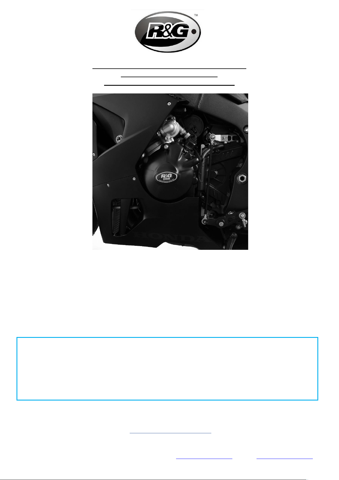
•Offer up the R&G cover to the engine and carefully fit it over the casing. Ensure that the three R&G
bolt holes are lined up with the holes in the engine casing, and then push the case on as far as it will
go.
•Fit the two cap head bolts (item 3) through the Engine Case Cover and into the engine case in the
two rearward mounts, do not tighten at this stage.
•Place the included M6 x 45mm button head bolt (item 2) into the hole nearest the front of the bike,
marked with a star on the diagram above.
•With hex keys, tighten the bolts equally so that they pull the cover into place. DO NOT FULLY
TIGHTEN.
•Finally use a torque wrench set at 10 N/m (7 Lb/ft) to fully tighten.
•Replace the fairing mount into its original position and tighten the fixing bolt. The button head bolt
(item 2) should sit under the fairing mount as shown in picture 5.
•Re-fit the belly pan by reversing the process which it was removed.
•It is suggested that you check the tightness of the mounting bolts on a regular basis i.e. when
cleaning or once a month.
•NOTE for the cleaning of this product you should only use a soft polishing cloth and a mild general
cleaning agent.
•AVOID HARMFUL CHEMICALS. IF IN DOUBT DO NOT USE AS THEY COULD ALTER THE STRENGTH OF
THE COVER.
•R&G will accept no liability if the above procedure and torque settings are not followed.
•Check all components are secure and all bolts are tight before riding.
ISSUE 1 –12/03/2021 (DM)
CONSUMER NOTICE
The catalogue description and any exhibition of samples are only broad indications of the Products and R&G may make design
changes which do not diminish their performance or visual appeal and supplying them in such state shall conform to the order.
The Buyer acknowledges no representation or warranty (other than as to title) has been given or will apply to the Products other
than those in R&G’s order or confirmation and the Buyer confirms it has chosen the Products as being of merchantable quality and
suitable for its particular purposes. Where R&G fits the Products or undertakes other services it shall exercise reasonable skill and
care and rectify any fault free of charge unless the workmanship has been disturbed. The Buyer is responsible for ensuring that
the warranty on the motorcycle is not affected by the fitting of the Products. On return of any defective Products R&G shall at its
option either supply a replacement or refund the purchase money but shall not be liable if the Products have been modified or
used or maintained otherwise than in accordance with R&G’s or manufacturer’s instructions and good engineering practice or if the
defect arises from accident or neglect. Other than identified above and subject to R&G not limiting its liability for causing death
and personal injury, it shall not be liable for indirect or consequential loss and otherwise its liability shall be limited to the amounts
paid by the Buyer for the Products or the fitting or service concerned. These terms do not affect the Buyer’s statutory rights.
R&G RACING RETURNS POLICY (NON-FAULTY GOODS)
Returns must be pre-authorised (if not pre-authorised the return will be rejected). Goods may only be returned direct to us if they
were purchased direct from us (customer must prove if necessary). Otherwise to be returned to original vendor. Goods must be
in re-sellable condition, in the opinion of R&G Racing. All returns are subject to a 25% restocking and handling fee (25% of the
gross value exc. P&P –at the prevailing price at time of purchase). The customer must pay any and all carriage charges. No returns
of discontinued products, unless within 14 days of purchase. This policy does not affect your statutory rights and does not refer to
faulty goods.

Page 6of 8ECC0310R
R&G Racing
Unit 1, Shelley’s Lane, East Worldham, Alton, Hampshire, GU34 3AQ
Tel: +44 (0)1420 89007 Fax: +44 (0)1420 87301 www.rg-racing.com Email: info@rg-racing.com
NOTICE DE MONTAGE POUR ECC0310R
PROTECTION CARTER MOTEUR CÔTÉ GAUCHE
HONDA CBR1000RR-R & SP 2020-
CE KIT CONTIENT LES ARTICLES ILLUSTRES ET ETIQUETES SUR LA PAGE.
CERTAINES PARTIES PEUVENT ETRE PRESENTES UNIQUEMENT POUR LA CLARTE DES INSTRUCTIONS.
NE PAS PROCEDER AU MONTAGE TANT QUE VOUS N'ETES PAS SUR QUE TOUTES LES PIECES SOIENT
PRESENTES.
VEUILLEZ LIRE TOUTES LES INSTRUCTIONS AVANT DE CONTINUER.
EN CAS DE DOUTE LORS DU MONTAGE DE NOS PRODUITS, CONSULTEZ UN DE NOS
REVENDEURS OU FAITES APPEL A UN TECHNICIEN QUALIFIÉ.
VEUILLEZ NOTER QUE LA FAÇON DONT LE KIT EST EMBALLE NE REPRESENTE PAS NECESSAIREMENT LA
MANIERE DE LE MONTER SUR LA MOTO.
SI DES RONDELLES EN CAOUTCHOUC SONT UTILISEES POUR MAINTENIR LES COMPOSANTS SUR LES
BOULONS,ELLES PEUVENT ETRE JETEES.
NOTICE DISPONIBLE AU TELECHARGEMENT SUR : WWW.RG-RACING.COM

Page 7of 8ECC0310R
R&G Racing
Unit 1, Shelley’s Lane, East Worldham, Alton, Hampshire, GU34 3AQ
Tel: +44 (0)1420 89007 Fax: +44 (0)1420 87301 www.rg-racing.com Email: info@rg-racing.com
OUTILS REQUIS
•Clés Allen 3mm, 4mm & 5mm
•Clé à molette 10mm
VALEURS DE SERRAGE
M4 BOULON = 8Nm
M5 BOULON = 12Nm
M6 BOULON = 15Nm
M8 BOULON = 20Nm
M10 BOULON = 40Nm
M12 BOULON = 40Nm
LÉGENDE
ARTICLE NO.
DESCRIPTION
QTÉ
ARTICLE 1
ECC0310R PROTECTION CARTER MOTEUR
1
ARTICLE 2
M6 x 1.00 x 45mm BOULON
1
ARTICLE 3
M6 x 1.00 x 45mm BOULON
2
NOTICE DE MONTAGE
•Veuillez vous assurer que le moteur soit froid avant de procéder au montage de la protection R&G.
•Pour commencer, le pan de ventre doit être retiré, pour ce faire, les panneaux latéraux inférieurs
gauche et droit peuvent être retirés en une seule unité. Placez d'abord un matériau souple sous la
moto pour éviter tout dommage au carénage lors du retrait.
•Retirez les deux fixations les plus reculées de chaque côté comme indiqué sur la photo 1 à l'aide
d'une clé hexagonale de 5 mm.
•Retirez les goupilles élastiques de la section intérieure du carénage ventral en appuyant sur la goupille
centrale et en retirant l'écarteur en plastique comme indiqué sur la photo 2.
•Tout en soutenant le pare-vent par le dessous, retirez les 3 boulons à tête hexagonale de chaque
côté comme indiqué sur la photo 3.
•Abaissez le carénage ventral de la moto comme indiqué sur la photo 4. Lors de l'abaissement, vous
devrez détacher soigneusement les tubes en caoutchouc des clips du carénage.
•À l'aide d'une douille de 10 mm, desserrez le boulon du support de carénage côté gauche et faites-
le pivoter pour l'éloigner du carter du moteur comme indiqué sur la photo 5.
•En vous référant à la photo 6, pour installer la protection carter moteur R&G, retirez les trois boulons
du carter du moteur M6 dans les positions indiquées par la flèche ci-dessus. Tenez la protection sans
serrer sur le boîtier pour aider à identifier les bons. NE RETIREZ PAS TOUS LES BOULONS DU CARTER
MOTEUR.
•Assurez-vous que les entretoises filetées pré-montées dans le carter soient serrées à la main contre
l'intérieur de la protection carter moteur (article 1).
•Présentez la protection R&G sur le moteur et placez-la soigneusement sur le carter. Assurez-vous
que les trois trous de boulons R&G soient alignés avec les trous du carter du moteur, puis poussez le
boîtier aussi loin que possible.
•Insérer les deux boulons à tête cylindrique (article 3) à travers la protection carter moteur et dans le
carter du moteur dans les deux supports arrière, ne pas serrer à ce stade.
•Placez le boulon à tête ronde M6 x 45 mm inclus (article 2) dans le trou le plus proche de l'avant de
la moto, marqué d'une étoile sur le schéma ci-dessus.

Page 8of 8ECC0310R
R&G Racing
Unit 1, Shelley’s Lane, East Worldham, Alton, Hampshire, GU34 3AQ
Tel: +44 (0)1420 89007 Fax: +44 (0)1420 87301 www.rg-racing.com Email: info@rg-racing.com
•À l'aide de clés hexagonales, serrez les boulons de manière égale pour qu'ils mettent la protection
en place. NE SERREZ PAS COMPLÈTEMENT.
•Enfin, utilisez une clé dynamométrique réglée à 10 N / m (7 Lb / ft) pour serrer complètement.
•Remettez le support de carénage dans sa position d'origine et serrez le boulon de fixation. Le boulon
à tête ronde (article 2) doit être placé sous le support de carénage comme indiqué sur la photo 5.
•Remontez la plaque ventral en inversant le processus de retrait.
•Il est conseillé de vérifier régulièrement le serrage des boulons de fixation, c'est-à-dire lors du
nettoyage ou une fois par mois.
•NOTE: Pour le nettoyage de ce produit, vous ne devez utiliser qu'un chiffon de polissage doux et un
agent de nettoyage général doux.
•ÉVITEZ LES PRODUITS CHIMIQUES NOCIFS. EN CAS DE DOUTE NE PAS UTILISER CAR ILS
POURRAIENT MODIFIER LA RÉSISTANCE DE LA COUVERTURE.
•R&G décline toute responsabilité si la procédure et les réglages de couple ci-dessus ne sont pas
respectés.
•Vérifiez que tous les composants soient sécurisés et que tous les boulons soient serrés avant de
rouler.
ISSUE 1 –12/03/2021 (DM)
Table of contents
Languages:
Other R&G Motorcycle Accessories manuals