Ratio Electric SMART BOX User manual

Manual
SMART BOX
DYNAMIC CHARGING + ENERGY METER

IMPORTANT SAFETY INSTRUCTION
S3
SAFETY INFORMATIO
N4
INSTALLATION 5
OPERATION 7
FRONT PANEL DISPLAY 7
OPTION
S8
SPECIFICATION
S9
MAINTENANCE 9
FCC INFORMATIO
N1
0
WARRANTY INFORMATION 11
CONTACT / CUSTOMER SUPPORT 12
2
CONTENTS
IMPORTANT SAFETY INSTRUCTIONS 3
SAFETY IFORMATION 4
INSTALLATION 5
SETUP MENU 7
USER INFORMATION 10
SPECIFICATIONS 14
MAINTENANCE 14
FCC INFORMATION 15
WARRANTY INFORMATION 16
CONTACT / CUSTOMER SUPPORT 16
CONTENTS

IMPORTANT SAFETY INSTRUCTIONS3
SAFETY INFORMATION4
INSTALLATION 5
OPERATION 7
FRONT PANEL DISPLAY 7
OPTIONS8
SPECIFICATIONS9
MAINTENANCE 9
FCC INFORMATION10
WARRANTY INFORMATION 11
CONTACT / CUSTOMER SUPPORT 12
2
CONTENTS
3
Carefully read these instructions and the charging instructions in your vehicle
owner’s handbook before charging your electrical vehicle.
Take special note of all information marked with the following symbols:
IMPORTANT SAFETY INSTRUCTIONS
Caution: This symbol means be careful. You are capable of
doing something that might result in damage to equipment.
Warning: This symbol means danger. You are in a situation
that could cause bodily injury. Before you work on any electrical
equipment, be aware of the hazards involved with electrical
circuitry and standard practices for preventing accidents.
Note:This means pay particular attention. Notes contain helpful suggestions
Safety Guidelines
Use this Smart Box to charge electric vehicles equipped with a
conductive charge port only. See the vehicle’s owner’s handbook to
determine if the vehicle is equipped with a conductive charge port.
Make certain the Smart Box’s supply cable is positioned so it will not be
stepped on, tripped over, or otherwise subjected to damage or stress.
There are no user serviceable parts inside. Refer to the Customer
Support section in this manual for service information. Do not attempt to
repair or service the Smart Box yourself.
Do not operate your Smart Box if it or the supply cable or housing is
visibly damaged. Switch off the MCB in the electrical cabinet and contact
your Service Representative for service immediately. Refer to the
Customer Support section in the manual for information on the Service
Representative in your area.
SMART BOX / Version: EV050

SAFETY INFORMATION
Warning: When using electric products, basic precautions should
always be followed, including the following:
Read all the safety warnings and instructions before using the product.
Failure to follow the warnings and the instructions may result in electric
shock, fire and / or serious injury.
This device should be supervised when used around children.
Do not put fingers into the electric vehicle connector.
Do not use this product if the flexible power cord or EV cable are frayed,
have broken insulation, or any other signs of damage.
Do not use this product if the enclosure or the EV connector are broken,
cracked, open, or show any other indication of damage
Warning:If, at any time, you think the equipment is unsafe, switch off
the MCB in your electrical cabinet and immediately contact Customer
Support for service. Do not use your Smart Box until the problem is
identified and corrected.
Caution: Children should not be allowed to use this Smart Box. Do not
allow children to play in or around the Smart Box. Close supervision of
children is necessary when the Smart Box is used.
Caution: Do not open the enclosure.
Note: This Smart Box is designed according the IEC61851 Mode 3 standard.
Note: This product must be grounded/protective earthed. If it should
malfunction or breakdown, grounding provides a path of least
resistance for electric current to reduce the risk of electric shock. This
product is equipped with a cord having an equipment grounding
conductor and a grounding plug.
Warning: Improper connection of the equipment-grounding conductor is
able to result in a risk of electric shock. Check with a qualified electrician
or serviceman if you are in doubt as to whether the product is properly
grounded.
4
5. Open bottom cover of the
Charge Station (5 screws –
see picture). Carefully brake
out required cable opening
for incoming power cable
and charge cable.
Use supplied M25 cable
gland to fix power cable
from the bottom.
Use supplied grommet to fix
power cable from the back.
Use supplied M25 cable gland
to fix charge cable.
6. Use 4 wood screws M4,5x35mm to mount Charging Station on the wall.
The Charging Station should be installed between 0,80m and 1,20m from
bottom to the ground.
Fixed cable Outlet
5
INSTALLATION
1. The installation must be done by a qualified and licenced electrician
according the local legislation.
2. The electrical installation must be free of power during the entire
installation period.
3. Since this Charging Unit uses circuits that reference to ground, no
Megging must be done after connecting to power.
4. Wiring and protection:
VersionWiring *Mains Circuit Breaker
(MCB)
Residual Current Device
(RCD)
32A / 1 Phase3G6,00mm230mA, Type A
32A / 3 Phase5G6,00mm2
*For cable length upto 25m
PLEASE NOTE: All charges include an AC (> 30mA) and
DC (> 6mA) residual-current-detection.
Always place a type A RCD and the MCB (or
combination unit) in the electrical cabinet.
SMART BOX / Version: EV050
SAFETY INFORMATION
Warning: When using electric products, basic precautions should
always be followed, including the following:
Read all the safety warnings and instructions before using the product.
Failure to follow the warnings and the instructions may result in electric
shock, fire and / or serious injury.
This device should be supervised when used around children.
Do not put fingers into the electric vehicle connector.
Do not use this product if the flexible power cord or EV cable are frayed,
have broken insulation, or any other signs of damage.
Do not use this product if the enclosure or the EV connector are broken,
cracked, open, or show any other indication of damage
Warning:If, at any time, you think the equipment is unsafe, switch off
the MCB in your electrical cabinet and immediately contact Customer
Support for service. Do not use your Smart Box until the problem is
identified and corrected.
Caution: Children should not be allowed to use this Smart Box. Do not
allow children to play in or around the Smart Box. Close supervision of
children is necessary when the Smart Box is used.
Caution: Do not open the enclosure.
Note: This Smart Box is designed according the IEC61851 Mode 3 standard.
Note: This product must be grounded/protective earthed. If it should
malfunction or breakdown, grounding provides a path of least
resistance for electric current to reduce the risk of electric shock. This
product is equipped with a cord having an equipment grounding
conductor and a grounding plug.
Warning: Improper connection of the equipment-grounding conductor is
able to result in a risk of electric shock. Check with a qualified electrician
or serviceman if you are in doubt as to whether the product is properly
grounded.
4
5. Open bottom cover of the
Charge Station (5 screws –
see picture). Carefully brake
out required cable opening
for incoming power cable
and charge cable.
Use supplied M25 cable
gland to fix power cable
from the bottom.
Use supplied grommet to fix
power cable from the back.
Use supplied M25 cable gland
to fix charge cable.
6. Use 4 wood screws M4,5x35mm to mount Charging Station on the wall.
The Charging Station should be installed between 0,80m and 1,20m from
bottom to the ground.
Fixed cable Outlet
5
INSTALLATION
1. The installation must be done by a qualified and licenced electrician
according the local legislation.
2. The electrical installation must be free of power during the entire
installation period.
3. Since this Charging Unit uses circuits that reference to ground, no
Megging must be done after connecting to power.
4. Wiring and protection:
VersionWiring *Mains Circuit Breaker
(MCB)
Residual Current Device
(RCD)
32A / 1 Phase3G6,00mm230mA, Type A
32A / 3 Phase5G6,00mm2
*For cable length upto 25m
PLEASE NOTE: All charges include an AC (> 30mA) and
DC (> 6mA) residual-current-detection.
Always place a type A RCD and the MCB (or
combination unit) in the electrical cabinet.
SMART BOX / Version: EV050
6
7. Connect in-coming power to the left
terminal block.
Single Phase :
L1=Brown
N= Blue
Earth= Green/Yellow
3 Phase
L1=Brown
L2=Black
L3=Grey
N=Blue
Earth=Green/Yellow
IMPORTANT: OUTLET VERSION - before closing outlet cover,
be sure the outlet is unlocked!
9. Close bottom cover and carefully slide metallized cover over the
Charge Station.
8. Connection Sensorbox
The Sensorbox should be placed where the Mains connection enters the
building. Usually just after the kWh meter, this way it will be able to
measure the total current per phase and send this information to the
Smart Box.
In order to measure the current, Current Transformers are used (type
SCT013-000, one for each phase). Clip them around the L1, L2 and L3
wires and plug the other end into the Sensorbox.
The data cable on the Sensorbox should be connected to terminals A
(white), B (yellow), +12V (brown) and GND (green).
NOTE: The data cable between Sensorbox and Smart Box is not
supplied. You can use a standard UTP cable or 4 x 0,25 mm2data cable.
Connect the data cable in the charging station with the supplied 4 pole
connector. Master/Slave configuration: Connect the A, B and GND
connection from the Master to the Slave(s). So A connects to A, B goes
to B etc. Make sure that the +12V wire coming from the Sensorbox is
connected to the Master Smart Box only.
7
7
SMART BOX / Version: EV050
SETUP MENU
To enter the setup menu press:
2 x left arrow button
1 x right arrow button
1 x left arrow button
1 x middle button
1 x left arrow button
After starting, the charger is always ready to charge with the previous settings.
You can’t access the setup during the charging.
In the menu you can choose between SETUP:
1. CHG MODE
2. LOAD BAL
3. I MAX HOME
4. I-MIN
5. I-MAX
6. I-CALkWh
7. I-CALsensor
8. READOUT -> ERR MEMORY
You can use the left or right arrow button to switch between the settings.
Conrm your choice always with the middle button.
1. SETUP CHG MODE
SETUP
<- CHG MODE ->
In the setup CHG MODE you can choose between:
SETUP CHG MODE
<- MANUAL ->
SETUP CHG MODE
<- FIXED 16 ->
SETUP CHG MODE
<- FIXED 32 ->
SETUP CHG MODE
<- SMART ->

8
MANUAL
You can set the charging current between 6A and 32A
(you can adjust the charging current during charging)
FIXED 16
with this option you can set the charging current to 16A
FIXED 32
with this option you can set the charging current to 32A
SMART
Load Balancing mode – the EV will charge with a
dynamic charge current, depending on Sensorbox data
and I-MAX HOME, I-MIN and I-MAX settings
You can change the setup by pressing the left or right arrow button.
After your choice has been made conrm by pressing the middle button.
2. LOAD BAL
It is possible to connect up to 4 Smart Box modules to each other and let them
share one mains supply. Congure the Smart Box’s load balancing option (LOAD
BAL) and set one module to MASTER, the others to SLAVE 1,2,3.
Make sure there is only one Master, and the Slave numbers are unique. Example:
for two units set the rst module to Master and second to Slave 1.
SETUP
<- LOAD BAL ->
DISABLED – no load balancing is used
MASTER – set one of the Smart Box’s to Master
SLAVE 1-3 – set the rest of the Smart Box’s to Slave 1-3, when using load balancing
In the setup LOAD BAL you can choose between:
SETUP CHG MODE
<- DISABLED ->
SETUP CHG MODE
<- MASTER ->
SETUP CHG MODE
<- SLAVE 1 ->
SETUP CHG MODE
<- SLAVE 2 ->
SETUP CHG MODE
<- SLAVE 3 ->
6
7. Connect in-coming power to the left
terminal block.
Single Phase :
L1=Brown
N= Blue
Earth= Green/Yellow
3 Phase
L1=Brown
L2=Black
L3=Grey
N=Blue
Earth=Green/Yellow
8. Close bottom cover and carefully slide metallized cover over the Charge Station.
IMPORTANT: OUTLET VERSION - before closing outlet cover,
be sure the outlet is unlocked!

9
7
SMART BOX / Version: EV050
You can change the setup by pressing the left or right arrow button.
After your choice has been made conrm by pressing the middle button.
You can only use load balancing in SMART mode.
3. SETUP I-MAX HOME
Here you can set the maximum available current of your house.
To set MAX Mains current you can choose between 10A and 99A.
This setup is available in SMART mode.
4. SETUP I-MIN
SETUP
<- I-MIN ->
Here you can set the minimum charging current.
You can choose between 6A and 16A with steps of 1A.
The standard setting is 6A.
To make your choice please use the left or right arrow button.
To conrm press the middle button.
5. SETUP I-MAX
SETUP
<- I-MAX ->
Here you can set the maximum charging current for the EV.
You can choose between 10A and 32A with steps of 1A.
To make your choice please use the left or right arrow button.
To conrm press the middle button.
6. SETUP I-CALkWh
SETUP
<- I-CALkWh ->
CALIBRATE BUSY
XX
ALREADY
CALIBRATED
The calibration has already been done. It is possible to calibrate the charger only
once.

10
7. SETUP CALsensor
SETUP
<- CALsensor ->
Iactual: xx.x
CALVAL
<- x.x ->
The correct setting is 3.0.
8. READOUT -> ERR MEMORY
SETUP
<- ERR MEMORY ->
E 1:
E 2:
E 3:
E 4:
E 5:
Conrm with the middle button to enter
the error memory screen. You can see max. 10 error codes.
With the left and right arrow buttons you can scroll to the last code.
To return into the setup menu please press the middle button for 5 seconds.
In case of error message please contact Ratio Electric for support.
1 PHASE CHARGE STATION
The charging display depends on the chosen charger mode -> MANUAL, FIXED 16,
FIXED 32, SMART.
With the right arrow button you can always enter the screen with more information
about the consumption of the charger.
6
7. Connect in-coming power to the left
terminal block.
Single Phase :
L1=Brown
N= Blue
Earth= Green/Yellow
3 Phase
L1=Brown
L2=Black
L3=Grey
N=Blue
Earth=Green/Yellow
8. Close bottom cover and carefully slide metallized cover over the Charge Station.
IMPORTANT: OUTLET VERSION - before closing outlet cover,
be sure the outlet is unlocked!
USER INFORMATION

11
6
7. Connect in-coming power to the left
terminal block.
Single Phase :
L1=Brown
N= Blue
Earth= Green/Yellow
3 Phase
L1=Brown
L2=Black
L3=Grey
N=Blue
Earth=Green/Yellow
8. Close bottom cover and carefully slide metallized cover over the Charge Station.
IMPORTANT: OUTLET VERSION - before closing outlet cover,
be sure the outlet is unlocked!
7
SMART BOX / Version: EV050
CHARGING SMART MODE
Charger ready, not connected to EV
smart (m) -> master
smart (s1) -> slave 1 / smart (s2) -> slave 2 / smart (s3)
-> slave 3
Charger connected to EV
Charging display
I set [A] – available current
Pt [W] – power
Et [kWh] – total consumption (never reset)
lh – x x : measured current ( x x ) : setting I HOME MAX
As in all other chosen charger modes you can reach the next screen with the right
arrow button.
The menu below can be reached with the arrow button from a READY TO CHARGE
screen but also from CHARGING screen.
Here you can nd more information about the consumption:
I: current (A)
U: voltage (V)
P: power (kWh)
Et: total kWh value (never canceled)
By pressing the middle button, you can see the meter readings of the last 5
sessions.
The values can be deleted by pressing the left and right
arrow buttons at the same time.
With the middle button you can go back to the previous
screen.
READY TO
CHARGE (A)
mode: smart (m)
www.ratio.nl
READY TO
CHARGE (B)
mode: smart (m)
www.ratio.nl
CHARGING
I set [A] : x x
Pt [W] : x . x
Et [kW] : kWh
lh : x x x x x x ( x x )
www.ratio.nl
I: A
U: V
P: kWh
Et: kWh
www.ratio.nl
Et (1): kWh
Et (2): kWh
Et (3): kWh
Et (4): kWh
Et (5): kWh

CHARGER ERROR
In case of the charger error, you will see the error screen
with the error code. If multiple errors occur the codes will
alternate.
By error message please contact Ratio Electric for
support.
To return into the setup menu please press the middle
button for 5 seconds.
3 PHASE CHARGE STATION
The charging display depends on the chosen charger mode -> MANUAL, FIXED 16,
FIXED 32, SMART. With the right arrow button you can always enter the screen with
more information about the consumption of the charger.
CHARGING SMART MODE
Charger ready, not connected to EV
smart (m) -> master
smart (s1) -> slave 1 / smart (s2) -> slave 2 / smart (s3)
-> slave 3
Charger connected to EV
Charging display
I set [A] – available current
Pt [kW] – power
Et [kWh] – total consumption (never reset)
lh – x x : measured current per phase ( x x ) :
setting I HOME MAX
As in all other chosen charger modes you can reach the next screen with the right
arrow button.
12
6
7. Connect in-coming power to the left
terminal block.
Single Phase :
L1=Brown
N= Blue
Earth= Green/Yellow
3 Phase
L1=Brown
L2=Black
L3=Grey
N=Blue
Earth=Green/Yellow
8. Close bottom cover and carefully slide metallized cover over the Charge Station.
IMPORTANT: OUTLET VERSION - before closing outlet cover,
be sure the outlet is unlocked!
CHARGER
NOT READY
ERR: ….................….
www.ratio.nl
READY TO
CHARGE (A)
mode: smart (m)
www.ratio.nl
READY TO
CHARGE (B)
mode: smart (m)
www.ratio.nl
CHARGING
I set [A] : x x
Pt [kW] : x . x
Et [kW] : kWh
lh : x x x x x x ( x x )
www.ratio.nl

6
7. Connect in-coming power to the left
terminal block.
Single Phase :
L1=Brown
N= Blue
Earth= Green/Yellow
3 Phase
L1=Brown
L2=Black
L3=Grey
N=Blue
Earth=Green/Yellow
8. Close bottom cover and carefully slide metallized cover over the Charge Station.
IMPORTANT: OUTLET VERSION - before closing outlet cover,
be sure the outlet is unlocked!
13
7
SMART BOX / Version: EV050
The menu below can be reached with the arrow button from a READY TO CHARGE
screen but also from CHARGING screen.
Here you can nd more information about the consumption:
I: current (A)
U: voltage (V)
P: power (kWh)
Et: total kWh value
(never reset)
By pressing the middle button, you can see the meter readings of the last 5
sessions.
The values can be deleted by pressing the left and right
arrow buttons at the same time.
With the middle button you can go back to the previous
screen.
CHARGER ERROR
In case of the charger error, you will see the error screen
with the error code. If multiple errors occur the codes will
alternate.
By error massage please contact Ratio Electric for
support.
To return into the setup menu please press the middle
button for 5 seconds.
I 1: A
I 2: A
I 3: A
U 1: V
U 2: V
U 3: V
P 1: kWh
P 2: kWh
P 3: kWh
Et: kWh
Et (1): kWh
Et (2): kWh
Et (3): kWh
Et (4): kWh
Et (5): kWh
CHARGER
NOT READY
ERR: …..................….
www.ratio.nl

14
6
7. Connect in-coming power to the left
terminal block.
Single Phase :
L1=Brown
N= Blue
Earth= Green/Yellow
3 Phase
L1=Brown
L2=Black
L3=Grey
N=Blue
Earth=Green/Yellow
8. Close bottom cover and carefully slide metallized cover over the Charge Station.
IMPORTANT: OUTLET VERSION - before closing outlet cover,
be sure the outlet is unlocked!
15
SPECIFICATIONS
IEC 61851 Mode 3
IEC 62196 Type 1 and type 2
single-phase or 3 phase, 230V-400V, 16 A and 32A
3.7kW, 7.4kW, 11kW, 22kW
400mm x 250mm x 105mm
PC/ABS
4 kg (incl. cable)
IP54, rain-tight
-25°C to +40°C
Charging System
Cable version car connector
Power input
Power output
Dimensions
Housing
Weight
Environment Operating
Temperature
Marking
MAINTENANCE
The Smart Box requires no maintenance other than occasional cleaning.
Warning: Switch off your Smart Box before cleaning the unit.
Warning To reduce the risk of electrical shock or equipment damage,
be cautious while cleaning the connectors and case.
Clean the Smart Box using a soft cloth lightly moistened with mild detergent
solution. Never use any type of abrasive pad, scouring powder, or flammable
solvents such as alcohol or benzene.
SMART BOX / Version: EV050
IEC 62196 Type 2 Outlet
Outlet version
IEC 62196 Type 2 Outlet
Outlet version
16
FCC INFORMATION
This device complies with Part 15 of the FCC rules. Operation is subject to the
following two conditions: (1) This device may not cause harmful interference, and
(2)This device must accept any interference received, including interference that
may cause undesired operation.
This product has been designed to protect against Radio Frequency Interference
(RFI). However there are some instances where high powered radio signals or
nearby RF-producing equipment (such as digital phones, RF communications
equipment, etc.) could affect operation.
If interference to your charge station is suspected, we suggest the following
steps be taken before consulting your Service Representative for assistance:
1. Reorient or relocate nearby electrical appliances or equipment during
charging.
2. Turn off nearby electrical appliances or equipment during charging.
Caution: Changes or modifications to this product by other than an
authorized service facility may void FCC compliance.

6
7. Connect in-coming power to the left
terminal block.
Single Phase :
L1=Brown
N= Blue
Earth= Green/Yellow
3 Phase
L1=Brown
L2=Black
L3=Grey
N=Blue
Earth=Green/Yellow
8. Close bottom cover and carefully slide metallized cover over the Charge Station.
IMPORTANT: OUTLET VERSION - before closing outlet cover,
be sure the outlet is unlocked!
15
7
SMART BOX / Version: EV050
16
FCC INFORMATION
This device complies with Part 15 of the FCC rules. Operation is subject to the
following two conditions: (1) This device may not cause harmful interference, and
(2)This device must accept any interference received, including interference that
may cause undesired operation.
This product has been designed to protect against Radio Frequency Interference
(RFI). However there are some instances where high powered radio signals or
nearby RF-producing equipment (such as digital phones, RF communications
equipment, etc.) could affect operation.
If interference to your charge station is suspected, we suggest the following
steps be taken before consulting your Service Representative for assistance:
1. Reorient or relocate nearby electrical appliances or equipment during
charging.
2. Turn off nearby electrical appliances or equipment during charging.
Caution: Changes or modifications to this product by other than an
authorized service facility may void FCC compliance.
Other manuals for SMART BOX
1
Table of contents
Other Ratio Electric Batteries Charger manuals

Ratio Electric
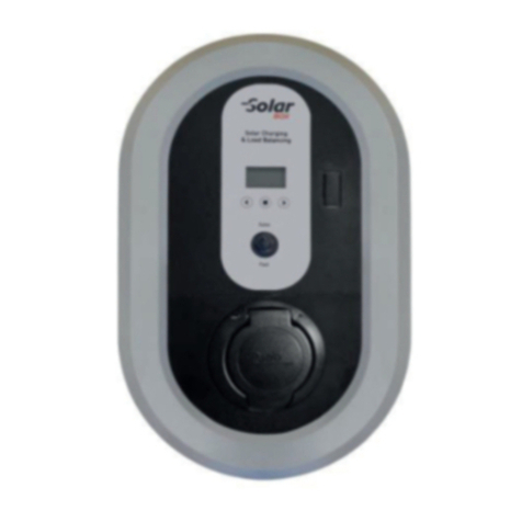
Ratio Electric SOLAR BOX User manual

Ratio Electric
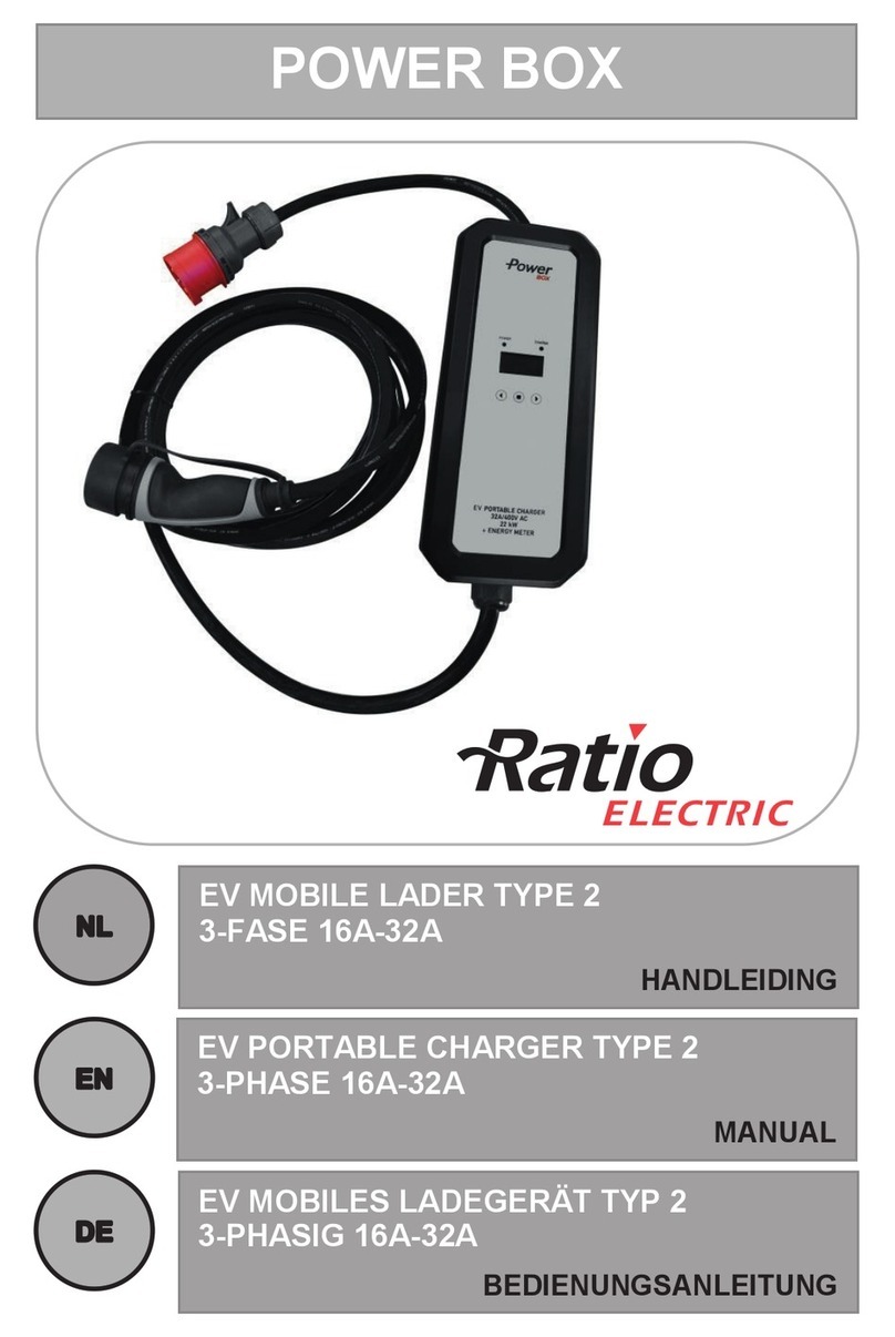
Ratio Electric POWER BOX User manual

Ratio Electric
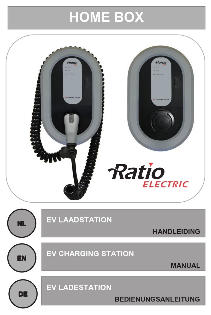
Ratio Electric HOME BOX User manual

Ratio Electric
Ratio Electric SOLAR BOX User manual

Ratio Electric
Ratio Electric SMART BOX User manual

Ratio Electric
Ratio Electric HOME BOX PLUS User manual

Ratio Electric
Ratio Electric HOME BOX PLUS User manual

Ratio Electric
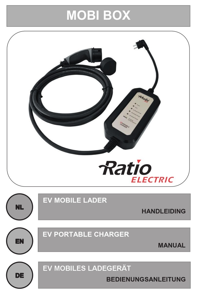
Ratio Electric MOBI BOX User manual