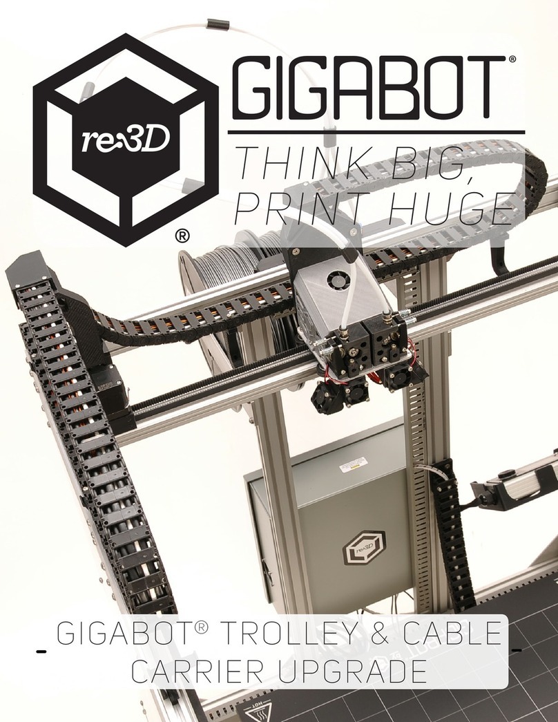
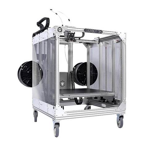
re:3D Gigabot User manual

re3D
Assembling Gigabot: "Everything's in the Box"
Here's how to construct your Gigabot after your kit arrives in the mail, or is picked up from Texas.
We're writing this guide assuming you're starting from the Gigabot Kit, also known as "Everything's
in the Box".
Written By: Chris Gerty
Assembling Gigabot: "Everything's in the Box" Draft: 2015-04-24Guide ID: 1 -
This document was generated on 2019-09-29 02:46:26 AM (MST).
© 2019 re3d.dozuki.com/ Page 1 of 66

Step 1 — Assembling Gigabot: "Everything's in the Box"
Find a suitable place to construct
your Gigabot
Find a firm, flat surface that is free
from debris.
Try to assemble where Gigabot
will be permanently printing
Keep in mind that once
constructed, Gigabot will not fit
through most standard doors
Skim through most of this guide, so
that you understand the scope of
what you need to do, and if you
need help from a partner during
assembly.
Assembling Gigabot: "Everything's in the Box" Draft: 2015-04-24Guide ID: 1 -
This document was generated on 2019-09-29 02:46:26 AM (MST).
© 2019 re3d.dozuki.com/ Page 3 of 66

Step 2 — Base Assembly Preparation
Locate 4 Corner Plates with no identifiers or logos. See Fig. 3-1.
Insert an M5 x 8mm BHCS (button head cap screw) in all 7 holes and fasten loosely with T-nuts.
Locate 4 Triangle Braces. See Fig. 3-2.
Insert 2 M5 x 12mm BHCS in each Triangle Brace. Use 2 M5 washers per BHCS. Loosely
fasten a T-nut on the opposite end.
Note: DO NOT use Cross rail with “Gigabot” label until instructed to.
Locate 2 Cross rails (33.5” extrusion that has 2 tapped holes on each side )(not the Bed Cross
Rails). See Fig. 3-3.
This will be the bottom/back cross portion of the frame.
Assembling Gigabot: "Everything's in the Box" Draft: 2015-04-24Guide ID: 1 -
This document was generated on 2019-09-29 02:46:26 AM (MST).
© 2019 re3d.dozuki.com/ Page 4 of 66

Step 3 — Base Assembly - Rear/Lower Rail
Install 2 Corner Plates, one to each end of of one Cross rail (this will be the rear/lower cross rail).
See Fig. 4-1.
Slide in Corner Plate with T-nuts loosened. Ensure the edges are lined up and the bracket
edges are flush with the bottom and end of each rail. Lightly fasten down the bolts to prevent
movement.
Temporarily screw 2 M5 x12mm BHCS (button head cap screws) and 2 M5 washers per BHCS
into T-nuts . Insert the 2 T-nuts in what will be the top channel of rail. See Fig. 4-2.
Note: The BHCS and washers will be used later to fasten vertical rails that hold the
power box.
Fasten a Triangle Brace to each end of rail (lower inner channel). See Fig 4-3.
Place near end and keep T-nuts loose to allow for adjustment.
Assembling Gigabot: "Everything's in the Box" Draft: 2015-04-24Guide ID: 1 -
This document was generated on 2019-09-29 02:46:26 AM (MST).
© 2019 re3d.dozuki.com/ Page 5 of 66

Step 4 — Base Assembly – Rear / Lower Cross Rail Panduit Installation
Locate the 30” long Panduit, this is slightly shorter, and approx. one half the width and height of the
larger and longer 30.5" Panduit. See Fig. 5-1.
Fasten 3 M5x8 mm BHCS (button head cap screws) evenly along length, and 3 T-nuts to the
Panduit piece as shown in Fig. 5-1. Spacing of the t-nuts along the Panduit is not critical for this
step.
Keep the bolts loose to slide the Panduit to the top inside channel of the rail, then tighten the bolts.
See Fig. 5-2.
Ensure proper orientation of the rail with respect to the Corner plates, by observing 2 T-nuts on
the upper channel. See Fig. 5-2.
Assembling Gigabot: "Everything's in the Box" Draft: 2015-04-24Guide ID: 1 -
This document was generated on 2019-09-29 02:46:26 AM (MST).
© 2019 re3d.dozuki.com/ Page 6 of 66

Step 5 — Base Assembly – Side Plate/Rail Preparation
Locate 2 Side Plates, 2 Common Rails (31.5" long) and 2 12” Panduit pieces (shallow Panduit).
Observe orientation of bolt hole patterns. See Fig. 6-1.
Insert 4 M5 x 8mm BHCS (button head cap screws) on each side plate. Loosely put on T-nuts.
The 4 BHCS should be inserted in opposing directions on each plate. See Fig. 6-2 for
orientation of front.
Slide 1 common rail on the "inside" side of each side plate and center the rail. See Fig. 6-3.
Assembling Gigabot: "Everything's in the Box" Draft: 2015-04-24Guide ID: 1 -
This document was generated on 2019-09-29 02:46:26 AM (MST).
© 2019 re3d.dozuki.com/ Page 7 of 66

Step 6 — Base Assembly – Side Plate/Rail Preparation
Install Panduit on each side rail.
DO NOT tighten bolts at this
time.
Fasten 2 M5x8mm BHCS and 2
T-nuts to the Panduit piece.
With BHCSs loose, slide the
Panduit to the top, inside channel
of the rail. See Fig. 7-1 for
orientation.
Repeat for other side. Then add 6
M5X8mm BHCS to 6 T-nuts
above rail on side plates as
shown in picture.
Warning!!! Warning!!! Warning!!!
This step is easy to miss,
because these T-nuts are not
used until step 18. And it can't be
done later. Insert 2 T-nuts into the
top channel of each Common Rail
installed on the side plates. These
T-nuts can be seen in the top
channel near the end of the Panduit
in Fig. 7-1.
Assembling Gigabot: "Everything's in the Box" Draft: 2015-04-24Guide ID: 1 -
This document was generated on 2019-09-29 02:46:26 AM (MST).
© 2019 re3d.dozuki.com/ Page 8 of 66

Step 7 — '''Base Assembly & Front Lower Cross Rail Preparation'''
Orient each side rail on table and connect with the Rear / Lower Cross Rail assembled in step 5
and 6, by sliding the T-nut of the Triangle Brace on each side into the lower channel of each side
rail. See Fig. 8-1
Ensure all of the BHCS (button head cap screws) are still loose in the Corner Plates and the
Triangle Braces. Square the corner and screw in 2 M5 x 12mm BHCSs on each end of the Cross
Rail. These are the 2 tapped holes on each end of the rail. See Fig. 8-2.
Assembling Gigabot: "Everything's in the Box" Draft: 2015-04-24Guide ID: 1 -
This document was generated on 2019-09-29 02:46:26 AM (MST).
© 2019 re3d.dozuki.com/ Page 9 of 66

Step 8 — Base Assembly – Installing Front/Lower Cross Rail
Position front/lower Cross rail assembly in front to complete the square of the frame base.
Assembly should be similar to Rear/Lower Cross Rail assembly See Fig. 9-1.
Do not tighten bolts yet.
Square the corners (without tightening any bolts).
Insert 2 M5 x 12mm BHCS (button head cap screws) through the side plates into the ends of the
Cross rail (these are the 2 tapped holes on each end of the rail).
Align the frame and then tighten the bolts in this order:
While compressing the front to back of each side, tighten M5 x 12mm BHCS (4 /side or 8 total).
Tighten M5 x 8mm bolts on each side plate. (4 /side or 8 total). See Fig. 9-2.
Tighten both bolts in each of the 4 triangle braces. While tightening, pull each brace into the
corner to ensure it is flush against each Cross and Common rail (8 total). See Fig. 9-3.
Assembling Gigabot: "Everything's in the Box" Draft: 2015-04-24Guide ID: 1 -
This document was generated on 2019-09-29 02:46:26 AM (MST).
© 2019 re3d.dozuki.com/ Page 10 of 66

Step 9 — Z-Upright Preparation and Installation
Locate the 4 Z-Uprights. These have a notch cut on one end.
Do not tighten T-Nuts yet.
Insert 6 M5 x 8mm BHCS (button head cap screws) in each bottom side plate. Attach T-nuts.
See Fig. 10-1.
Install each Z-upright with the notch facing up and inside frame. See Fig. 10-2.
After the extrusion is in place, center it with respect to the bolts (while loose move back and
forth and feel for the center position).
Square each one at a time and tighten the bolts. See Fig. 10-3.
Assembling Gigabot: "Everything's in the Box" Draft: 2015-04-24Guide ID: 1 -
This document was generated on 2019-09-29 02:46:26 AM (MST).
© 2019 re3d.dozuki.com/ Page 11 of 66

Step 10 — Z- Upper Side Plate assembly preparation
Locate 2 Side plates.
Insert 10 M5 x 8mm BHCS (button head cap screws) with T-nuts into each side plate (these will
be used to fasten to the Z-uprights). See Fig. 10-1.
Locate 2 Runway Rails (Y-axis). Each rail has a single hole on one side and 2 holes on the other.
Slide one Runway Rail to each side plate. See Fig. 10-2.
Note the location of holes on the Runway Rails with respect to the hole pattern on the side plate.
See Fig. 10-3.
Assembling Gigabot: "Everything's in the Box" Draft: 2015-04-24Guide ID: 1 -
This document was generated on 2019-09-29 02:46:26 AM (MST).
© 2019 re3d.dozuki.com/ Page 12 of 66

Step 11 — Install Z-Upper side plate assemblies
Slide right and left plates onto vertical supports. Leave BHCS (button head cap screws) loose. See
Fig. 11-1 and 11-2.
Insert 2 M5 x 8mm BHCSs and T-nuts into remaining 2 holes at each end of each bottom slide
plate. (8 total)
Insert 2 M5 x 8mm BHCSs and T-nuts into 2 holes, mirroring the holes from the previous step, at
each end of each top slide plate. (8 total) See Fig. 11-3.
Assembling Gigabot: "Everything's in the Box" Draft: 2015-04-24Guide ID: 1 -
This document was generated on 2019-09-29 02:46:26 AM (MST).
© 2019 re3d.dozuki.com/ Page 13 of 66

Step 12 — Install 4 Vertical Supports (Common Rails)
Locate 4 Common Rails (vertical supports for each corner of frame), and 2 31.5” Shallow Panduits
For each corner, slide the common rail vertically down, starting at the top of frame. See Fig. 13-1.
Starting with the 2 T-nuts at top corner on the side plate, slide down the rail to connect it with the 5
exposed T-nuts in each corner.
Do not fully tighten BHCS (button head cap screws) yet.
Once in place, loosely tighten up 5 BHCSs in each lower corner (3 BHCSs on Corner Plate and
2 BHCSs on Side Plates). See Fig. 13-2.
Install shallow panduit on each rear vertical rail. See Fig. 13-3. Note that the shallow Panduit is
used on both vertical rails. The image shows deep panduit on one side, but it is actually only
intended for the upper and lower rear rails.
Fasten 3 M5 x 8mm BHCS and 3 T-nuts onto each panduit piece. With the bolts still loose, slide
the panduit to the inner channel of the vertical. Tighten bolts at this time.
Assembling Gigabot: "Everything's in the Box" Draft: 2015-04-24Guide ID: 1 -
This document was generated on 2019-09-29 02:46:26 AM (MST).
© 2019 re3d.dozuki.com/ Page 14 of 66

Step 13 — Preparation for Front & Rear / Upper Cross Rails
Locate 4 Corner Plates, including
the one with the Gigabot logo and
the one with the Serial number.
Locate 2 Cross rails (33.5” extrusion
with 2 tapped holes on each side).
If one of the 2 remaining Cross
supports located has a
“Gigabot” label, this Cross rail
will be used for the front.
Insert an M5 x 8mm BHCS (button
head cap screw) in each of 7 holes
of each of the 4 Corner plates and
fasten loosely with T-nuts. See Fig.
14-1.
Assembling Gigabot: "Everything's in the Box" Draft: 2015-04-24Guide ID: 1 -
This document was generated on 2019-09-29 02:46:26 AM (MST).
© 2019 re3d.dozuki.com/ Page 15 of 66

Step 14 — Assemble and attach Upper Cross Rails
Attach the re:3D Logo Corner plate to the left and blank Corner Plate to the right.
Front Cross Rail Preparation: Slide in the Corner Plate with T-nuts loosened. Ensure the edges
are lined up and that the bracket edges are flush with the edge and end of each rail.
Rear Cross Rail Preparation: Prior to installing the corner plate, place 2 T-nuts on the
outside/upper channel and 1 T-nut on the outside/lower channel. Attach the rear filament guide /
bracket. See Fig. 15-1.
Attach the Serialized Corner Plate so that the text is readable and the blank Corner Plate on the
other side. Ensure the edges are lined up and that the bracket edges are flush with the edge
and end of each rail. See Fig. 15-2.
This step is easy to miss too! Place 2 T-nuts in the bottom channel of rear / upper cross rail.
Secure with 2 M5 x 12mm BCHS (button head cap screws) and 2 washers each.
When this Cross Rail is installed these T-nuts and washers will mirror the 2 T-Nuts and
washers on the bottom Cross Rail.
Slide in the rear and front Cross rail assemblies to the respective sides of the frame from the top.
Do not tighten. See Fig. 15-3.
Assembling Gigabot: "Everything's in the Box" Draft: 2015-04-24Guide ID: 1 -
This document was generated on 2019-09-29 02:46:26 AM (MST).
© 2019 re3d.dozuki.com/ Page 16 of 66

Step 15 — Panduit and Complete top of Frame Part 1
Install Panduit on right plate. Use 7” length “shallow” Panduit for right support.
For this installation, hold the Panduit in position and insert 2 M5 x 8mm BCHS (button head cap
screws) from outside, then fasten with 2 M5 hex nuts from the inside. Tighten bolts at this time.
See Fig. 16-1.
Insert 2 M5 x 12mm BCHS through the side plates into the end of each cross rail (8 total). DO NOT
tighten. See Fig. 16-2.
Insert 3 M5 x 45mm BCHSs on each side of top side plate.
2 go through the side plate and Runway Rail (Y-axis), near the rear of frame, and 1 goes
through the side plate and Runway Rail (Y-axis) near the front of frame.
Placement is to ensure frame is aligned. These bolts will be removed in a later step and will be
used to attach the Y-Axis motors. See Fig. 16-3.
Assembling Gigabot: "Everything's in the Box" Draft: 2015-04-24Guide ID: 1 -
This document was generated on 2019-09-29 02:46:26 AM (MST).
© 2019 re3d.dozuki.com/ Page 17 of 66

Step 16 — Panduit and Complete Top of Frame Part 2
This is a 2-person operation. Ensure the top of the Runway Rails (Y-axis) is aligned with the top
of the corner uprights, then tighten bolts in this order:
While compressing the front and rear of each side, tighten M5 x 12mm BCHS (button head cap
screws) (8 total).
Tighten 4 M5 x 8mm BCHS on each side plate. (8 total)
Tighten 3 loose bolts in each of the 4 corner plates.
Tighten all bolts on the mid section of the side plate. (10 each side)
Remove the 3 M5 x 45mm BCHS from each side.
All bolts on the frame should now be tight and the frame should be square.
Assembling Gigabot: "Everything's in the Box" Draft: 2015-04-24Guide ID: 1 -
This document was generated on 2019-09-29 02:46:26 AM (MST).
© 2019 re3d.dozuki.com/ Page 18 of 66

Step 17 — Z-axis Rod assembly preparation
Locate 2 Lower Bearing Blocks, 2 Upper Bearing Blocks, 2 Z Motor Pulleys, 2 XML Belts (Z-axis),
2 nut cups, 2 ACME threaded rods and 2 threaded rod pulleys.
Install the Lower bearing blocks on each side (right and left) using the 2 T-nuts already installed
and 2 M5 x 12mm BCHS (button head cap screws).
Position as shown in Fig. 18-1. Keep bolts loose.
Install nut cup on ACME Rod towards bottom of rod (end with 2 flat edges on tip). See Fig. 18-2
for orientation of nut cup.
Warning: Threaded rod may have a very sharp thread on bottom (first thread).
Assembling Gigabot: "Everything's in the Box" Draft: 2015-04-24Guide ID: 1 -
This document was generated on 2019-09-29 02:46:26 AM (MST).
© 2019 re3d.dozuki.com/ Page 19 of 66

Step 18 — Z-axis Rod assembly installation
Note: Repeat the following operations for the left and right sides.
When installing the two threaded rod pulleys be sure they are positioned 1/16" above the shoulder
on the bottom of the threaded rod. Once assembled this will ensure there is a small air gap
between the belt pulley and the bearing below it. Install threaded rod pulley on lower end of ACME
rod (end with 2 flat edges on tip).
Tighten 2 set screws against the flat edges of Z-rod.
Loop XML belt around pulley. See Fig. 19-1.
Install this Z-rod subassembly by first inserting pulley end into lower bearing.
Install upper bearing block onto Z-rod subassembly. Using 2 M5 x 12mm BCHS (button head cap
screws), fasten the upper bearing to the inside of the side plate and then tighten the bolts. See Fig.
19-2.
Before tightening the lower bearing block, check the vertical alignment using the two sight
holes and the supplied alignment tool (U-shaped 3D printed item in snappy box) on the
bottom side plate as seen in Fig. 19-3. Tighten the bolts once alignment is verified.
Assembling Gigabot: "Everything's in the Box" Draft: 2015-04-24Guide ID: 1 -
This document was generated on 2019-09-29 02:46:26 AM (MST).
© 2019 re3d.dozuki.com/ Page 20 of 66
Other manuals for Gigabot
9
Other re:3D 3D Printer manuals

re:3D
re:3D Gigabot User manual

re:3D
re:3D GIGABOT 3+ User manual

re:3D
re:3D Gigabot User manual
re:3D
re:3D Gigabot User manual

re:3D
re:3D Gigabot User manual

re:3D
re:3D Gigabot User manual
re:3D
re:3D Gigabot User manual

re:3D
re:3D TERABOT User manual

re:3D
re:3D Gigabot User manual

re:3D
re:3D gigabot User manual