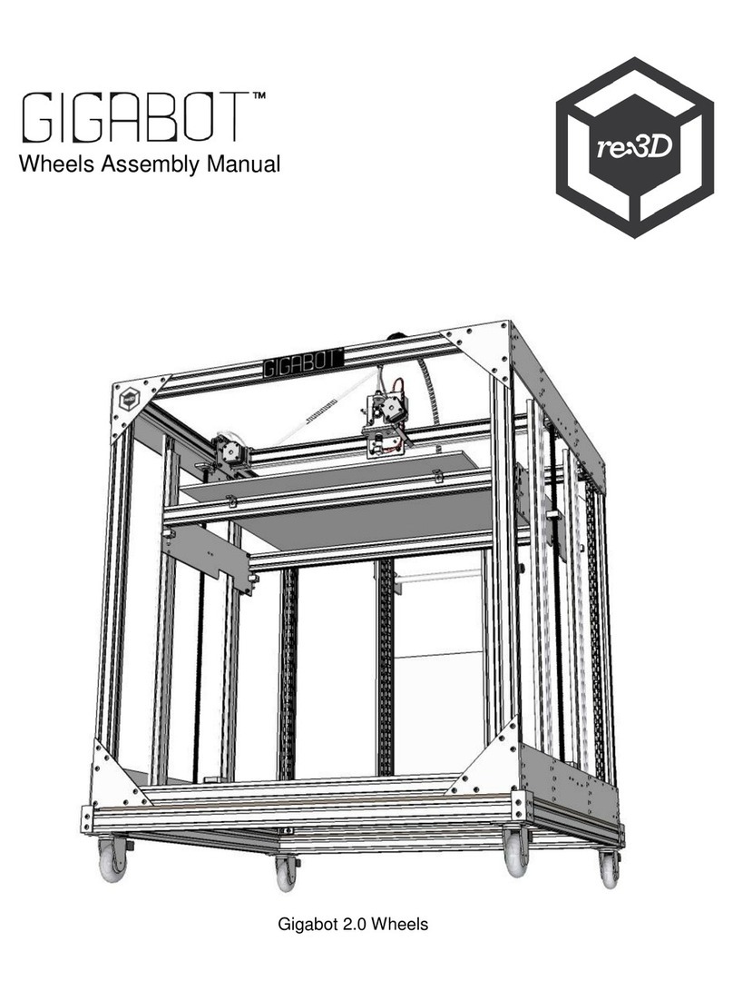
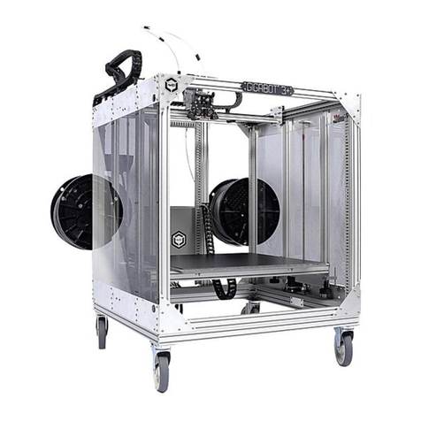
re:3D Gigabot User manual

think big,
print huge
gigabot® : unassembled
(complete diy kit)


Thank you for purchasing the Gigabot®: Unassembled
(Complete DIY Kit)!
references & helpful documents
video instructions
community forum
introduction
This kit contains all the parts necessary to construct a fully functioning Gigabot®. You will find
that this is a high quality and very capable 3D printer that not only helps you develop your
biggest ideas, but lets you do so at the human scale.
Some external resources may be helpful during the assembly process. For example, knowing
the correct names for dierent parts on the Gigabot®, or proper use of certain tools. Resources
that we thought may be helpful have been linked to at the end of this guide.
If you prefer a video guide, go to our YouTube channel at https://www.youtube.com/user/
GigaBot3D and find our related Gigabot® 3 assembly instructions. Retrofits, tips & tricks, and
other video content are available as well.
See what other users are doing with their Gigabot® and share your experiences on our forum:
https://re3d.zendesk.com/hc/en-us/community/topics
Rev. Dec 2016

legalese
read instructions
retain instructions
heed warnings
follow instructions
cleaning
attachments
water and moisture
ventilation
power sources
placement
All the safety and operating instructions must be read before the printer is operated.
The safety and operating instructions should be retained for future reference.
All warnings on the product and in the operating instructions should be adhered to.
All operating and use instructions should be followed
Unplug this product from the wall outlet before cleaning. Do not use liquid or aerosol cleaners.
Do not use any attachments or enhancements not recommended by the product manufacturer as
they may cause hazards.
Do not use Gigabot® near water - for example, near a bath tub, wash bowl, kitchen sink, or laundry
tub, in a wet basement, or near a swimming pool, and the like.
Slots and openings in the cabinet are provided for ventilation and to ensure reliable operation
of the product and to protect it from overheating, and these openings must not be blocked or
covered. The openings should never be blocked by placing the product on a bed, sofa, rug, or
other similar surface. This product should not be placed in a built-in installation such as a bookcase
or rack unless proper ventilation is provided or the manufacturer’s instructions have been adhered
to.
This product should be operated only from the type of power source indicated on the marking
label. If you are not sure of the type of power supply to your home consult your appliance dealer
or local power company. For products intended to operate from battery power, or other sources,
refer to the operating instructions.
Do not place this product on an unstable cart, stand, tripod, bracket, or table. The product may fall,
causing serious injury to a child or adult, and serious damage to the product. Use only with a cart,
stand, tripod, bracket, or table recommended by the manufacturer, or sold with the product. Any
mounting of the product should follow the manufacturer’s instructions, and should use a mounting
accessory recommended by the manufacturer.

Grounding or polarization
power-cord protection
lightning
overloading
object and liquid entry
This product may be equipped with either a polarized 2-wire AC line plug (a plug having one
blade wider than the other) or a 3-wire grounding type plug, a plug having a third (grounding) pin.
The 2-wire polarized plug will outlet, try reversing the plug. If the plug still fails to fit, contact your
electrician to replace your obsolete outlet. Do not defeat the safety purpose of the polarized plug.
The 3-wire grounding type plug will fit into a grounding type power outlet. This is a safety feature.
If you are unable to insert the plug into the outlet, contact your electrician to replace your obsolete
outlet. Do not defeat the safety purpose of the grounding type plug.
Power-supply cords should be routed so that they are not likely to be walked on or pinched by
items placed upon or against them, paying particular attention to cords at plugs, convenience
receptacles, and the point where they exit from the product.
For added protection for this product during a lightning storm, or when it is left unattended and
unused for long periods of time, unplug it from the wall outlet and disconnect the antenna or cable
system. This will prevent damage to the product due to lightning and power-line surges.
Do not overload wall outlets, extension cords, or integral convenience receptacles as this can
result in a risk of fire or electric shock. A product and cart combination should be moved with care.
Quick stops, excessive force, and uneven surfaces may cause the product and cart combination
to overturn.
Never push objects of any kind into this product through openings as they may touch dangerous
voltage points or short-out parts that could result in a fire or electric shock. Never spill liquid of any
kind on the product.

Table of Contents
Legend 1
Before You Build 2
Side Plate Assembly 5
Header & Footer Assembly 21
Bridge Assembly 36
Bed Frame Assembly 55
Frame Assembly 86
Squaring The Frame 113
Threaded Rods & Z Motor Installation 128
Bed Frame & Bed Plate Installation 141
F.D., Y Motor, & Z Limit Switch Installation 166
Wiring: Y Supports & Electrical Box 176
Wiring: Preliminary Routing 191
Wiring: Connect Components & Cover Panduits 204
Wiring: Trolley Wiring 214
WIRING: CABLE CARRIERS & PANDUIT COVERS 229
Viki Holder Installation 256

First Boot 265
Z Cable Carrier Installation 276
Side Panel, Name plate, & spool holder 283
next steps 295
conclusion 296
references & documents 297

gigabot®: unassembled
1
Legend
insert fasten measure
evenly space
connect Locate
place align
removemark route
Objects of important are outlined with
dotted lines, or highlighted.

gigabot®: unassembled 2
Before You Build
For the visual learners
It’s hip to be square
We have recorded instructional videos of our technicians assembling the Gigabot and posted them to
our YouTube channel. These work as a great standalone resource, but can also help clarify the printed
instructions. This manual references them quite often, so do not hesitate to cross reference this manual
and the video content if needed.
When assembling the Gigabot it is essential to work on a flat surface and to carefully square perpendicular
parts as much as possible. This is apparent in section F of this manual, but also in other areas such as
the bed frame construction. It is just as important to ensure that part surfaces are flush with each other
and not misaligned.

gigabot®: unassembled
3
The uses of grease
T-nuts, how do they work?
During Gigabot assembly, grease is most important for the Z-axis ACME threaded rods as well as the
assembly of wheels with eccentric spacers and to keep screw threads from galling. These situations are
pointed out in this manual and will enable ease of assembly and smooth, quiet operation while printing.
T-nuts are an essential part of assembling the Gigabot. These are inserted into the extrusion in order
to fasten parts to the frame. Post-assembly T-nuts, or “magic T-nuts,” as we like to call them, are also
used. These hold their positions without sliding around, and are useful especially when modifying or
retrofitting Gigabot without having to disassemble the frame.

gigabot®: unassembled 4
Measuring and marking
Some steps in the instructions will prompt you to mark locations on Gigabot in order to correctly locate
and place parts. When marking, be sure to only use a pencil-using a permanent marker will leave unsightly
marks on the metal!

Side Plate
Assembly

tools & parts
partbox #
watch the
accompanying
video:
quantity
Runway rails (Makerslide)
Common rails
Precision square
Allen keys
T-nuts
M5x8 BHCS
M5x45 BHCS
Idler Pulleys
M5 flat washers
M5 lock nut
Grease
8mm Combo Wrench
Corner plate (to be used as a guide)
Bed cross rail, dual extruder leveling
block, or any extra rail (to be used as
a guide)
https://youtu.be/BvHsYGNJj-0
2
2
1
1
24
24
2
2
4
2
1
1
1
1
4
4
1
6
Snappybox
Snappybox
Snappybox
Snappybox
Snappybox
Snappybox
6
Snappybox
6
4
Refer to packing list to identify parts
gigabot®: unassembled 6

gigabot®: unassembled
7
In the final assembly of Gigabot®, the side plate subassemblies will be oriented
in the frame as shown.
Top
Bottom
Front
Rear
Left Right
Runway rails
Common rails
overview

gigabot®: unassembled 8
Work on a flat surface.
Use a precision square and corner plate to check hole alignment
and make the side plates flush with their rails.
Be mindful of the orientation of each side plate.
Tips & Tricks
#1
#2
#3

A1
A2
A3
First, you will assemble
the lower side plates. Do
a quick visual check to
make sure the holes are
relatively aligned. Use
a corner plate and the
precision square to align
the plates.
Work on a flat surface
Place side plates
alongside each other,
mirrored from each other
as shown
gigabot®: unassembled
9

A4
A5
A6
Place the common rail
between the side plates,
as shown
6 T-nuts need to be placed
in each rail as marked in
yellow. See the diagram,
or see this section in the
video at 2:53.
Insert the T-nuts and line
them up to the side plate
holes. This doesn’t have
to be perfect, but get
them fairly close.
gigabot®: unassembled 10

A7
A8
A9
Place the side plate onto
the rail and use 6 M5x8s
and 3mm Allen Key to
loosely fasten the plate to
the rail. You can move the
plate along the common
rail to align the T-nuts to
the holes if needed.
Repeat this for the other
side plate and rail. Make
sure that they are still
mirrored. See the diagram
to distinguish which
belongs on the left and
right sides of the frame.
Use a bed frame cross
rail, or the dual extruder
leveling block along with
the corner plate and
the precision square to
correctly space the rail
from the ends of the side
plate. See the video at
5:42 for more.
gigabot®: unassembled
11
Left
Right

A10
A11
A12
Press the rail and plate
down and snug up the
M5x8s.
Check that the rail and
plate are flush on the
bottom surfaces.
Once flushed and spaced
correctly, fully tighten the
6 M5x8s
gigabot®: unassembled 12

A13
A14
A15
Repeat the spacing and
flushing process for the
other lower side plate
assembly. Refer to the
video for other useful tips.
Next, you will assemble
the upper side plate
assemblies. Similar to
before, place the side
plates mirrored alongside
each other, with the power
switch holes facing out.
Place the runway rails
between the side plates
with the single slot side
down as shown. Note that
the side with the single
slot should also be facing
outward.
gigabot®: unassembled
13
Other manuals for Gigabot
9
Table of contents
Other re:3D 3D Printer manuals

re:3D
re:3D Gigabot User manual

re:3D
re:3D Gigabot User manual

re:3D
re:3D Gigabot User manual

re:3D
re:3D Gigabot User manual

re:3D
re:3D Gigabot X User manual

re:3D
re:3D TERABOT User manual

re:3D
re:3D Gigabot User manual

re:3D
re:3D Gigabot User manual

re:3D
re:3D Gigabot User manual

re:3D
re:3D Gigabot User manual