re:3D Gigabot User manual

Bed Frame
& Bed Plate
Installation

tools & parts
partbox # quantity
Eccentric spacers
8mm combo wrench
M5 lock nuts
Grease
M5x8 BHCS
M5x30 BHCS
Bed plate
V-groove wheels
M5x35 FHS
M5 flat washer
T-nuts (used for placement, then removed)
M5 lock nut
Springs
3mm Allen Key
M5 flat washers
4
1
8
1
4
4
1
4
4
4
4
4
4
1
8
Snappybox
Snappybox
Snappybox
6
Snappybox
Snappybox
2
Snappybox
Snappybox
Snappybox
Snappybox
Snappybox
Snappybox
6
Snappybox
Refer to packing list to identify parts
gigabot®: unassembled 142
watch the
accompanying
video:
https://youtu.be/94aglYOQW_0

gigabot®: unassembled
143
There are two main steps in this section: Installing the bed frame to the Gigabot®, and then installing
the bed plate.
overview

gigabot®: unassembled 144
Work on a flat surface.
Take the time to properly align and fasten the nut cups to the
bed side plates. This will ensure smooth movement of the bed
as it goes up and down.
Align the left edge (looking from the front) of the bed plate with
the pencil marks on the bed cross rail to properly position it on
the bed frame.
Tips & Tricks
#1
#2
#3

h1
h2
h3
You will now install the
bed frame and then the
bed plate on top of that.
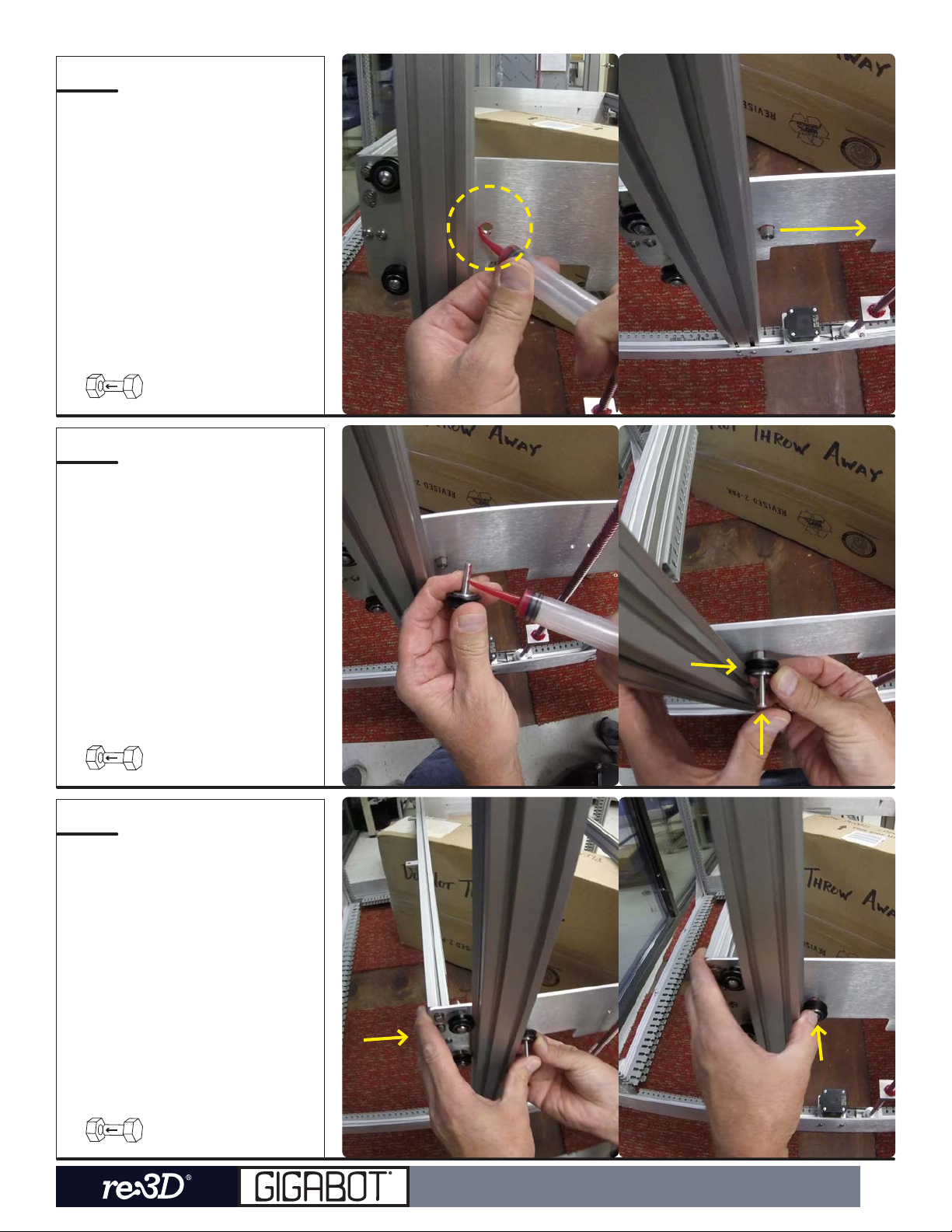
First, check that the
threaded rods are
securely seated inside the
bearings of the bearing
blocks.
If they are not seated,
press them into the
bearing before continuing
on.
gigabot®: unassembled
145

h4
h5
h6
Repeat H2-H3 on the
other side.
Place an object in the
middle to hold the bed
frame. Here, we use a box
that is placed diagonally
for more stability.
Without using a prop to
hold the bed frame, the
lower side plates will
interfere with installing
the remaining wheels to
secure the bed frame to
the Z-Uprights.
gigabot®: unassembled 146

h7
h8
h9
Here, the bed frame
Panduit has been
oset from center to
accomodate the box that
will prop it up.
Carefully lower the bed
frame down into the
Gigabot® frame.
Place the bed frame on
top of your prop, which
each of the bed frame
wheels resting against the
Z-uprights.
gigabot®: unassembled
147
h10
h11
h12
Apply grease to the outer
edge of one of the holes
near the rear of the bed
frame. Insert the eccentric
spacer here such that the
mark (thinnest side) is
facing away from the rail.
Insert a M5x30 BHCS into
a V-groove wheel. Apply
grease along the screw
threads and insert it into
the eccentric spacer. It is
easier to place the wheel
onto the rail and then
insert the screw, as shown
on the right.
Place pressure on the
rear of the bed frame and
insert the M5x30 BHCS
through the wheel and
spacer.
gigabot®: unassembled 148

h13
h14
h15
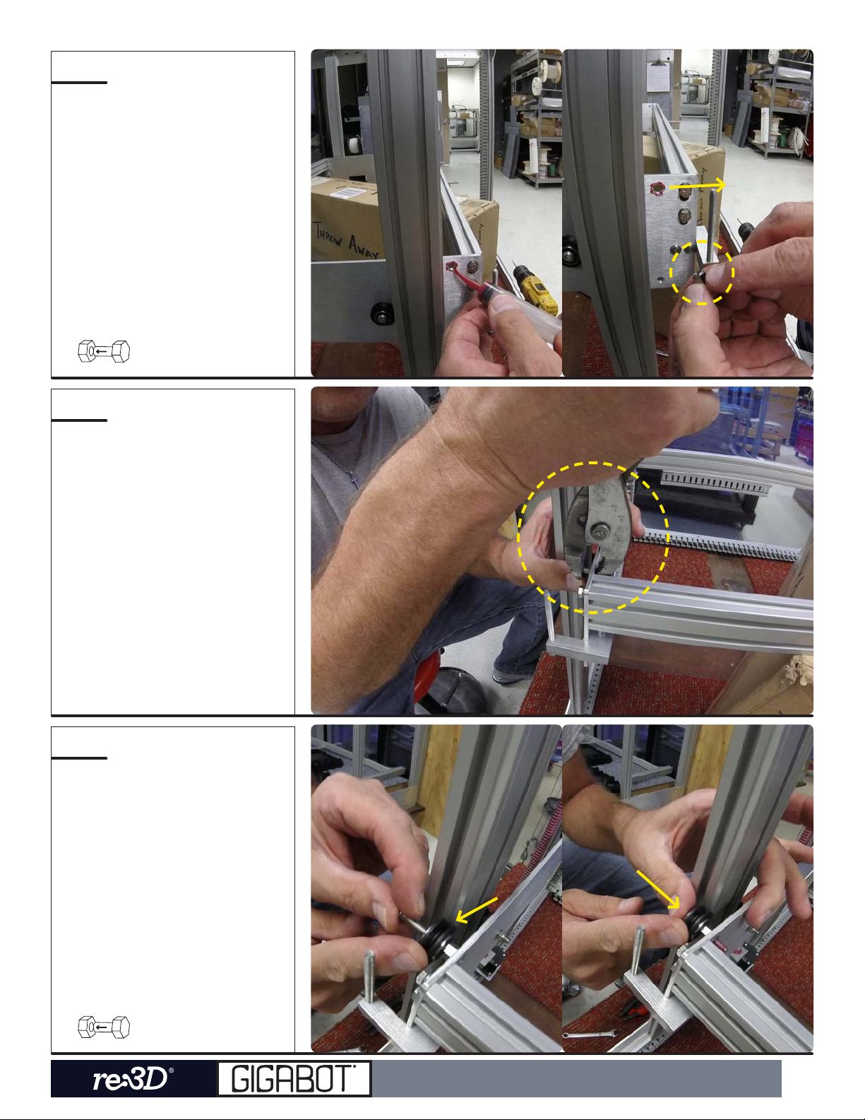
Place an M5 flat washer
on the screw.
Fasten an M5 lock nut
onto the same screw and
fasten this into place using
an 8mm wrench and 3mm
Allen Key. Refer to the bed
frame assembly section
for other examples of
fastening the wheels.
You have now secured
the bed frame onto one of
the rear Z-Uprights.
gigabot®: unassembled
149
h16
h17
h18
Repeat H10-H14 for the
wheels in the front of
this same side of the
bed frame. Again, the
eccentric spacer should
be positioned such that
the mark (marked on the
thinnest side) faces away
from the rail.
If the eccentric spacer is
dicult to insert into the
bed side plate, it may be
pressed into place with
the help of pliers.
Insert another V-groove
wheel in the same way as
in H12.
gigabot®: unassembled 150
Other manuals for Gigabot
9
Table of contents
Other re:3D 3D Printer manuals

re:3D
re:3D Gigabot User manual

re:3D
re:3D Gigabot User manual

re:3D
re:3D Gigabot User manual

re:3D
re:3D TERABOT User manual

re:3D
re:3D Gigabot User manual

re:3D
re:3D Gigabot User manual

re:3D
re:3D gigabot User manual

re:3D
re:3D Gigabot X User manual

re:3D
re:3D GIGABOT 3+ User manual

re:3D
re:3D Gigabot User manual


