Installation (General)
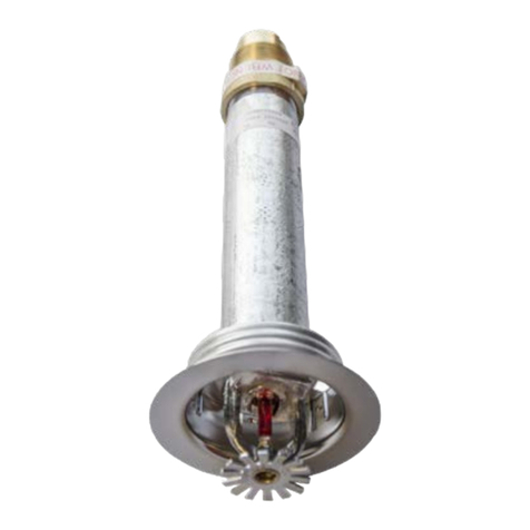
Dry sprinklers connected to wet pipe systems must be installed
as indicated in Figure 13 and as required by NFPA 13 with the
Exposed Minimum Barrel Length located in a heated area.
Reliable Model F3QR80 dry sidewall sprinklers may be installed in
ductile or malleable cast iron threaded tees, or CPVC tees and
adapters upon verication that the sprinkler inlet tting does not
interfere with the interior of the tting (see Figure 11).
DO NOT install Reliable Model F3QR80 dry sidewall sprinklers into
elbows or couplings, welded outlets, mechanical tees, or gasket
sealed CPVC ttings.
See Figure 12 for acceptable and unacceptable installation
practices.
F3QR80 with Standard Escutcheon
Cut a 2-1/8” (54mm) diameter hole in the wall as shown in Fig. 2.
Apply a PTFE based sealant to the sprinkler threads before installing
into the tting. Use the Model F3R installation wrench (see Fig. 5)
on the square boss to tighten the sprinkler until it is secured in the
sprinkler tting. Installation is completed by removing the orange
glass bulb protector and sliding the escutcheon over the nished
sleeve until tight to the nished surface.
F3QR80 with HB Escutcheon
Cut a 2-1/2” (64mm) diameter hole in the wall as shown in Fig. 3.
Apply a PTFE based sealant to the sprinkler threads before installing
into the tting. Use the Model F3R installation wrench (see Fig. 5)
on the square boss to tighten the sprinkler until it is secured in the
sprinkler tting. Installation is completed by removing the orange
glass bulb protector and sliding the skirt over the nished sleeve
until tight to the nished suface.
F3QR80 with FP Recessed Escutcheon
Cut a 2-5/8” (67mm) diameter hole in the wall as shown in Fig. 4.
Apply a PTFE based sealant to the sprinkler threads before installing
into the tting. Use the Model F3R installation wrench (see Fig. 8)
on the square boss to tighten the sprinkler until it is secured in the
sprinkler tting. Installation is completed by removing the orange
glass bulb protector and pushing (or threading) the FP escutcheon
into the threaded cup. Final adjustment is made by turning the FP
escutcheon clockwise until the flange makes full contact with the
wall surface.
F3QR80 CCP Concealed Cover Plate
Cut a 2-5/8” (67mm) diameter hole in the wall as shown in Fig. 5.
Apply a PTFE based sealant to the sprinkler threads before installing
into the tting. Use the Model F3R installation wrench (see Fig. 8)
on the square boss to tighten the sprinkler until it is secured in the
sprinkler tting. Installation is completed by removing the orange
glass bulb protector and pushing (or threading) the SWC cover
plate into the threaded cup. Final adjustment is made by turning
the cover plate clockwise until the cover plate flange makes full
contact with the nished surface.
Note:
1. The Model XLO2 installation wrench for recessed and
concealed installations has a open side to accommodate the
sprinkler deflector and can only be inserted in one way (see
Figure 9). Care must be taken not to damage the deflector
during installation.
2. Do not over-tighten sprinklers into ttings. It is recommended
that Reliable dry sprinklers be installed using the wrench
referenced in this bulletin. A pipe wrench may also be used
to install dry sprinklers provided that it only engages the outer
tube (steel pipe) of the assembly. Note that a pipe wrench
will impart a large amount of torque into the nal assembly.
This torque will need to be matched or exceeded to remove
the sprinkler at a later date. A leak free joint can normally be
obtained by installing the sprinkler to a minimum torque of 22
ft-lb (30 N.m) after applying an appropriate thread sealant.
3. Glass bulb sprinklers have orange bulb protectors to minimize
bulb damage during shipping, handling, and installation.
Reliable installation wrenches are designed to install
sprinklers while bulb protectors are in place. REMOVE THE
PROTECTORS AT THE TIME THE SPRINKLER SYSTEM IS
PLACED INTO SERVICE. Removal of the protectors before
this time may leave the glass bulb vulnerable to damage.
Remove protectors by undoing the clasp by hand. DO NOT
USE TOOLS TO REMOVE THE PROTECTORS.
4. Do not remove the wax llet in the gap between the cup that
supports the bulb and the wrenching boss.
Step 3
Step 2
Step 1
Figure 11
XLO2 Installation Procedure
Bulletin 061
November 2023
Page 11 of 16
www.reliablesprinkler.com