2.
Operation
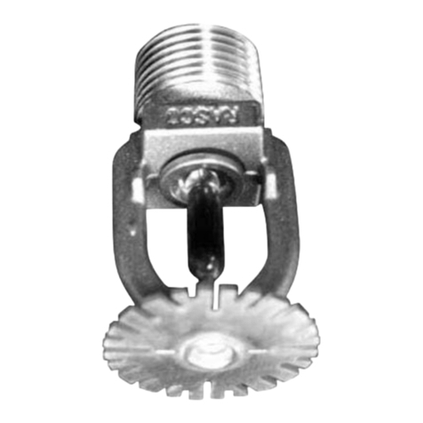
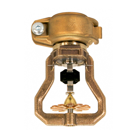
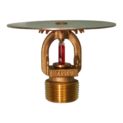
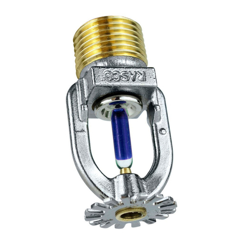
The Reliable Model N252 Extended Coverage Pendent
Control Mode Specific Application Storage Sprinklers
utilize a levered fusible alloy solder link. When the rated
temperature is reached, the solder melts and the two link
halves separate allowing sprinkler to operate and water
to flow.
FM Approved for the following:
1. Application: These FM Approved extended cover-
age CMSA automatic sprinklers may be used to pro-
tect Class 1 through 4, cartoned unexpanded plastic
commodities under ceilings up to and including 35
ft (10.7 m) high. They may be used to protect any
storage arrangement outlined in Data Sheet 8-9,
however portable racks must meet the guidelines re-
quired to be considered open-frame racks. Maintain
a minimum clearance of 3 ft (0.9 m) between the top
of storage and the sprinkler deflector.
Temperature Rating - The Reliable Model N252 EC
sprinkler is available in nominal temperature ratings
of either 165 °F (70 °C) or 212°F (100°C). Use the
nominally rated 165°F (70°C) sprinkler for all accept-
able applications unless the ambient temperature of
the protected occupancy requires the temperature
rating to be 212°F (100°C).
2. Hydraulic Design: Base the design for these auto-
matic sprinklers as follows:
Solid-Piled, Palletized, Shelf or Bin-Box and Open-
Frame Racks: See table 1
Storage Racks Equipped With Solid Shelves: Base
the design of the ceiling sprinkler system as outlined
above for open-frame racks, however base the need
for, as well as the design of, in-rack sprinkler protec-
tion the same as what is required for K16.8 (K240)
CMSA sprinklers.
Shape of Operating Area: Base the shape of the op-
erating area on a 1.2 shape factor for ceiling slopes
up to 5° or a 1.4 shape factor for ceilings having a
higher slope (up to 10° maximum).
3. System Type: Wet-pipe sprinkler systems or pre-
action sprinkler systems, whose sprinkler protection
design can be based on the equivalent of a wet-pipe
system, are acceptable.
4. Sprinkler Spacing: The minimum and maximum lin-
ear distances between sprinklers. are 10 ft (3.1 m)
and 14 ft (4.2 m), respectively for ceiling heights up
to and including 30 ft (9.0 m); for ceiling heights over
30 ft (9.0 m) and up to 35 ft (10.7 m) the maximum
linear spacing of the sprinkler is reduced to 12 ft (3.6
m), The minimum and maximum area of coverage
per sprinkler is 100 ft2(9 m2) and 196 ft2(18 m2), re-
spectively for ceiling heights up to and including 30
ft (9.0 m); for ceiling heights over 30 ft (9.0 m) and
up to 35 ft (10.7 m) the maximum area spacing of the
sprinkler is reduced to 144 ft2(13.5 m2).
5. Sprinkler Location from Walls: Locate the automat-
ic sprinklers with respect to walls, measured perpen-
dicular to the wall, as follows:
Minimum Horizontal Distance: 4 in. (100 mm)
Maximum Horizontal Distance unless indicated oth-
erwise in either the occupancy-specific data sheet or
the Approval Guide:
a. Wall Angle Greater Than 90°: 7 ft (2.1 m) for
ceilings up to 30 ft (9.0 m) high or 6 ft (1.8 m)
for ceilings over 30 ft (9.0 m) and up to 35 ft
(10.7 m) high.
b. Wall Angle Equal to or Less Than 90°: 10 ft
(3.0 m) for ceilings up to 30 ft (9.0 m) high or
8 ft (2.4 m) for ceilings over 30 ft (9.0 m) and
up to 35 ft (10.7 m) high.
6. Sprinkler Location from Ceilings: Locate the au-
tomatic sprinklers with respect to ceilings in accor-
dance with Data Sheet 2-0. However, the minimum
vertical distance below a ceiling can be reduced to
2 in. (50 mm) for smooth ceilings or 4 in. (100mm) for
non-smooth ceilings.
7. Obstructions: Use the obstruction guidelines out-
lined in D.S. 2-0 for extended coverage automatic
sprinklers in regards to the umbrella pattern. In ad-
dition, use the obstruction guidelines outlined in D.S.
2-0 for pendent automatic sprinklers in regards to
obstructions located below the automatic sprinkler,
except that an individual object up to a maximum
width of 1.25 in; (31 mm) can be tolerated less than
12 in. (300 mm) horizontally away from the sprinkler
as long as the object is located at least16 in. (400
mm) vertically below the sprinkler.
All other design details should be in accordance with
Data Sheet 8-9. All other installation details should be
in accordance with Data Sheet 2-0.
8. FM Global considers this a “Quick Response” Ex-
tended Coverage Sprinkler for use in Data Sheet 8-9.
9. For installations governed by NFPA #13 (2013), the
N252EC fire sprinkler meets the definition of Control
Mode Specific Application (CMSA) Sprinklers and is
approved for installation under chapter 21. Section
3.6.4.1. Section 8.11.1.1 states that CMSA sprinklers
shall be installed in accordance with Section 8.5 and
the manufacturer’s installation instructions.
