2.
The sprinkler uses a fast-response thermal element and
is available with a temperature rating of 155°F (68°C), 175°F
(79°C), or 200°F (93°C). Model SWC cover plates include a
conical concealed cover plate that is attached to a skirt with
temperature sensitive solder. Operation of the Model SWC cov-
er plate occurs when the solder melts due to an increase in the
surrounding temperature, allowing the cover plate to fall away
and exposing the Model DH80 Dry sprinkler. Model SWC cover
plates are available with a Temperature Rating of either 135°F
(57°C) for use with Ordinary Temperature Classication [155°F
(68°C)] sprinklers or 165°F for use with Intermediate Tempera-
ture Classication [175°F (79°C) and 200°F (93°C)] sprinklers.
Model DH80 dry sprinklers have a special wax llet placed
in the gap between the cup that supports the bulb and the
wrenching boss. This wax will not interfere with the operation of
the sprinkler, and it prevents contaminants from entering the in-
ternal portion of the drop nipple. The wax must not be removed.
Application
The Model DH80 Dry sprinkler is a horizontal sidewall dry
sprinkler intended for installation in light hazard occupancies
in accordance with NFPA 13. These sprinklers are designed
to provide re protection in long and narrow spaces such as
hallways, corridors, decks and portions of rooms up to 28 feet
(8.5 m) wide and 14 feet (4.3 m) long. They are rated for 175
psi (12 bar) and can be mounted between 4 and 12 inches
(102 and 305 mm) down from the ceiling. Model DH80 Dry
sprinklers may be installed on wet-pipe sprinkler systems in ac-
cordance with Fig. 8, as well as dry-pipe and preaction sprin-
kler systems.
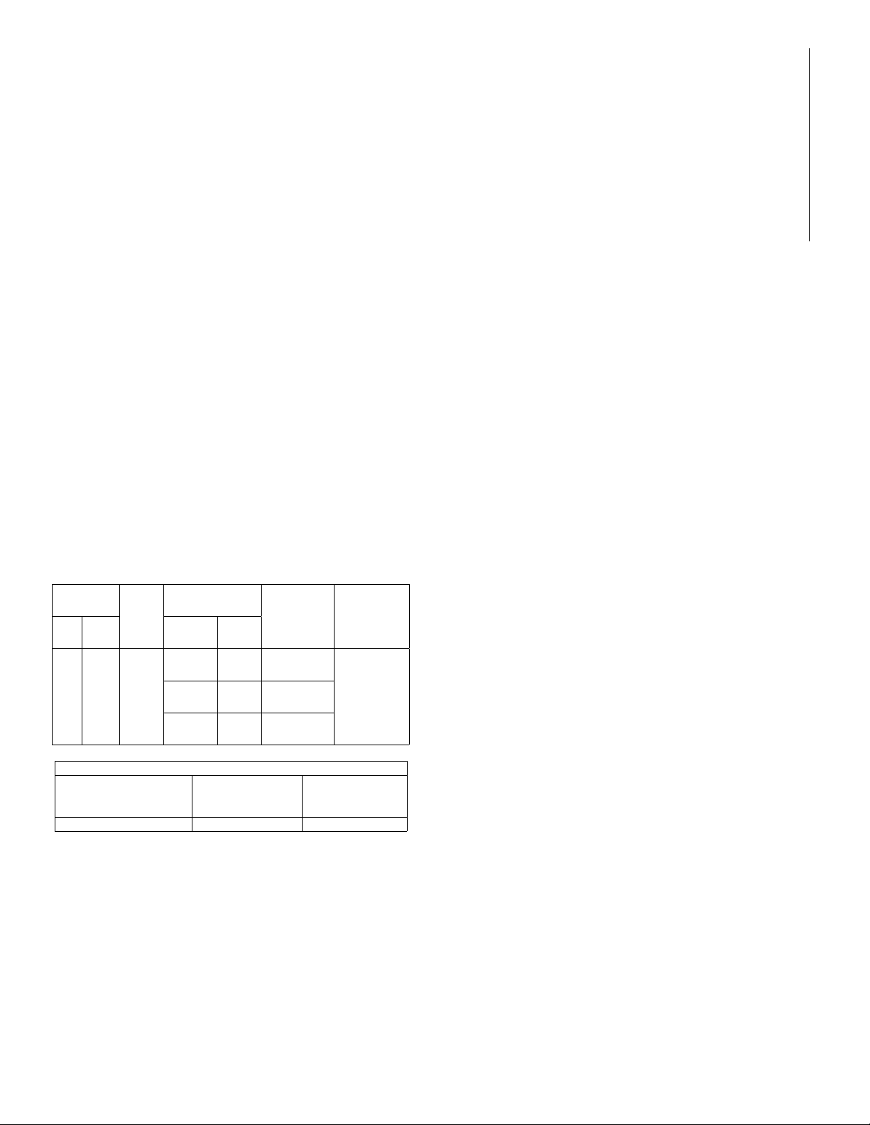
Technical Data:
Nominal
K-Factor Thread
Size
Temperature
Rating Maximum
Ambient
Temperature
Sprinkler
Identication
Number
(SIN)
US Met-
ric Sprinkler SWC
Cover
8.0 115
1” NPT
or
ISO
7-1R1
155°F
(68°C)
135°F
(57°C)
100°F
(38°C)
RA5532
175°F
(79°C)
165°F
(74°C)
150°F
(66°C)
200°F
(93°C)
165°F
(74°C)
150°F
(66°C)
Required Minimum Flow Rate and Pressure
Maximum Coverage
Area Width x Length
ft x ft (m x m)
Flow Rate
gpm (L/min)
Pressure
psi (bar)
28 x 14 (8.5 x 4.3) 40 (151) 25 (1.7)
Installation Instructions
Reliable Model DH80 dry sidewall sprinklers may be in-
stalled in ductile or malleable cast iron threaded tees, or CPVC
tees and adapters upon verication that the sprinkler inlet tting
does not interfere with the interior of the tting (see Figure 9).
DO NOT install Reliable Model DH80 dry sidewall sprinklers
into elbows or couplings, welded outlets, mechanical tees, or
gasket sealed CPVC ttings.
Dry sprinklers connected to wet pipe systems must be in-
stalled as indicated in Figure 8 and as required by NFPA 13 with
the Exposed Minimum Barrel Length located in a heated area.
A clip is provided to protect the glass bulb thermal element
from damage. The clip is factory installed on the sprinkler. The
clip should remain in place during installation of the sprinkler
and be removed when the sprinkler system is placed in service.
Model DH80 Dry sprinklers with the Model FP recessed es-
cutcheon or the Model SWC cover plate are also supplied with
a cap that can be used to provide additional protection for the
sprinkler during painting or nishing. The cap can be installed
without removing the clip. Both the cap and the clip must be
removed when the sprinkler system is placed in service.
Use the following steps for installation:
1. The centerline of the Model DH80 Dry sprinkler must be
installed between 4-5/8” (118 mm) and 12-5/8” (321 mm)
vertically below the nished ceiling so that the top of the de-
flector is not less than 4“ (102 mm) or more than 12” (305
mm) from the nished ceiling. A hole must be cut in the wall
directly in-line with the outlet of the tee. See the Installation
Data table for the recommended hole diameter based on
the escutcheon or cover plate option selected.
2. Apply pipe joint compound or Polytetrafluoroethylene
(PTFE) tape to the threads of the sprinkler’s inlet tting.
3. Install the sprinkler in the tee using the installation wrench
specied in the Installation Data table. The Model F3R
wrench is designed to be inserted into the groves in the
sprinkler’s wrench boss as shown in Fig. 3. The Model
XLO2 wrench is designed to t into the cup and engage the
wrench boss as shown in Fig. 2. Do NOT wrench any part
of the sprinkler assembly other than the wrench boss. When
inserting or removing the wrench from the sprinkler, care
should be taken to prevent damage to the sprinkler. The
sprinkler is then tightened into the pipe tting to achieve a
leak free connection. The recommended minimum to maxi-
mum installation torque is 22-30 lb-ft (30 – 40 N-m).
3a. Alternatively, where access to the outer tube of the sprinkler
is available, the Model DH80 Dry sprinkler may be installed
using a pipe wrench. The pipe wrench shall only be per-
mitted to interface with the steel outer tube portion of the
sprinkler (Item #8 in Fig. 10). Do NOT wrench any other por-
tion of the sprinkler assembly. A pipe wrench can install the
sprinkler into the tting with a large amount of torque; con-
sideration should be given to the need for future removal of
the sprinkler because the installation torque will have to be
matched or exceeded to remove the sprinkler. The recom-
mended minimum to maximum installation torque is 22-30
lb-ft (30 – 40 N-m).


