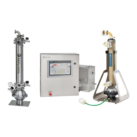
KrosFlo® TFDF™ Lab System
KrosFlo® TFDF™ Lab System
IF.UG.023 R1
List of tables
Table 1. Explanation of user attention phrases..................................................................................9
Table 2. Explanation of symbols.........................................................................................................9
Table 3. Instrument safety labels .....................................................................................................10
Table 4. ProConnex® TFDF™ Flow Path specifications .....................................................................17
Table 5. Sample and process ............................................................................................................31
Table 6. KrosFlo® TFDF™ Lab System permeate tubing flow rates ..................................................37
Table 7. Parameter data...................................................................................................................62
Table 8. Warning: Product use limitation.........................................................................................69
Table 9. System output.....................................................................................................................70
Table 10.System input.......................................................................................................................70
Table 11. System construction ...........................................................................................................70
Table 12. System environment ..........................................................................................................71
Table 13. System components list......................................................................................................71
List of figures
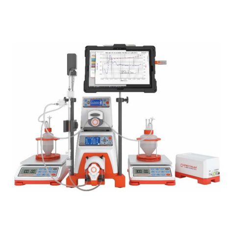
Figure 1. KrosFlo® TFDF™ Lab System ................................................................................................8
Figure 2. KrosFlo® TFDF™ Lab System Components ........................................................................11
Figure 3. Controller...........................................................................................................................11
Figure 4. Pump Station .....................................................................................................................12
Figure 5. ProConnex® TFDF™ Flow Path...........................................................................................13
Figure 6. Bench space needed..........................................................................................................14
Figure 7. Arranging the system on the bench ..................................................................................14
Figure 8. Assembling the stand ........................................................................................................15
Figure 9. System connections...........................................................................................................16
Figure 10.ProConnex® TFDF™ Flow Path configuration....................................................................17
Figure 11. Connecting pressure sensors ............................................................................................21
Figure 12. Making tubing connections ...............................................................................................22
Figure 13. Touchscreen display ..........................................................................................................23
Figure 14. Main Menu screen ............................................................................................................24
Figure 15. Menu bar...........................................................................................................................24
Figure 16. Screen navigation ..............................................................................................................25
Figure 17. Set-up before priming .......................................................................................................26
Figure 18. Primed system...................................................................................................................28
Figure 19. Experiment workflow ........................................................................................................32
Figure 20. Information screen............................................................................................................33
Figure 21. Main Menu screen ............................................................................................................34
Figure 22. Admin screen.....................................................................................................................35
Figure 23. System Settings screen......................................................................................................36
Figure 24. Reset Tubing Calibration ...................................................................................................37
Figure 25. PID loop settings screen....................................................................................................39
Figure 26. Alarm Set-up screen ..........................................................................................................40
Figure 27. Alarm Reset button ...........................................................................................................41
Figure 28. Alarm History screen.........................................................................................................42
Figure 29. Lock screen message.........................................................................................................42
Figure 30. Lock screen........................................................................................................................43
Figure 31. Data logging screen ...........................................................................................................43
Figure 32. Data Log Files.....................................................................................................................44
Figure 33. Recorded data example ....................................................................................................45
Figure 34. System Mode screen.........................................................................................................45
Figure 35. Concentration Mode Run Setpoints screen ......................................................................46
Figure 36. Concentration/Diafiltration Mode Run Setpoints screen .................................................47
