IF.PUG.001 R3
PRODUCT CONTENTS
Package includes the following:
•Membrane holder (cell)
oPolished Acrylic (Cat # TX001)
oPolished Polysulfone (Cat # TX 068)
•Tie Rods: 316L stainless steel
•Integrated top clamp: 316L stainless steel
•Membrane support: polypropylene screen
HOLDER SPECIFICATIONS
Holder Dimensions:
Width: 4.1” (10.4 cm)
Depth: 6” (15.2 cm)
Height:
•With handle lowered: 5.4” (13.7 cm)
•With handle raised: 8” (20.3 cm)
•Shipping Weight: 5 lbs. ( kg)
Membrane Diameter: 76mm
Effective Membrane Area: 30cm2
Pump Requirements:
Variable speed tubing pump
RPM: 10-600
Flow rate: 50-200 mL/min
MEMBRANE INSTALLATION
1. Open the integrated stainless steel clamp by lifting the colored handle.
Remove the clamp yoke by twisting it counter-clockwise and sliding it off
the guide-pins.
2. Lift the upper manifold off the base by sliding it up and over the guide-
pins.
3. Rinse the polypropylene membrane support screen with deionized (DI)
water or water for injection (WFI). Place it flat against the bottom
manifold; ensure that the screen is sitting flat in the manifold.
4. Obtain a 76mm membrane disc. Rinse the membrane disc with DI water
or WFI. Place it flat against the bottom manifold; ensure that the
membrane is flat on the membrane support screen and manifold.
5. Replace the upper manifold on the base by sliding it down over the guide-
pins.
6. Replace the clamp yoke by twisting it clockwise and sliding it onto the
guide-pins. Close the integrated stainless steel clamp by depressing the
colored handle.
7. Attach a piece of #16 tubing, approximately 18’ in length, to the feed
barb located in the center of the top manifold.
8. Attach a piece of #16 tubing, approximately 10’ in length, to the retentate
barb located on the left front of the top manifold. Also place a small
tubing clamp in the middle of the tubing attached to the retentate.
9. Attach a piece of #16 tubing, approximately 10’ in length, to the filtrate
barb located in the center of the lower manifold.
10. Thread the tubing attached to the feed through the head of a peristaltic
pump.
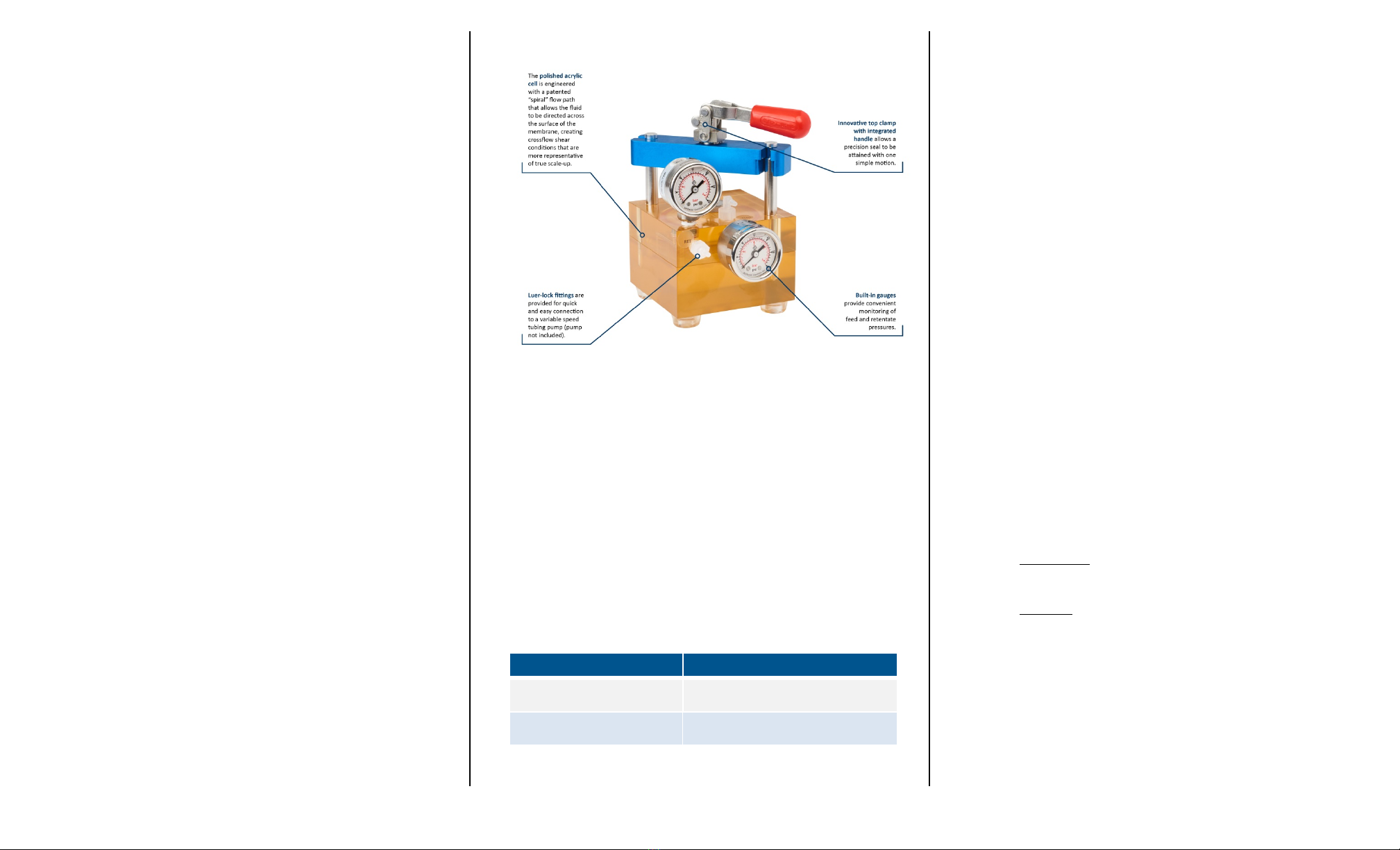
DEVICE DIAGRAM
FIRST TIME USE OF DEVICE
Once the membrane is installed, the device should be flushed with DI
water or WFI to ensure removal of the storage and preservative agents
from the membrane and to minimize any possible interaction with your
particular application. It is critical to use the highest quality water possible
to avoid fouling the membrane or introducing contaminants into the
system that could affect membrane performance and product recovery.
For some applications, further sanitization is required.
CLEANING OF DEVICE
The X-Flo76 device must be cleaned properly prior to reuse. To clean,
flush the device with a recommended cleaning solution from Table 2. Use
a minimum of 0.2 liters of cleaning solution. Upon completion of the
cleaning cycle, flush the device with buffer, WFI, or DI water prior to
storing.
Recommended Cleaning Solutions
Cleaning Agent Cleaning Conditions
0.1N to 0.5N Sodium
Hydroxide
Contact Time = 30 – 60 minutes
Temperature = 35°C (95°F)
1.5% Alconox® Detergent
Contact Time = 30 – 60 minutes
Temperature = 40°C (104°F)
MEMBRANE DISC STORAGE
A membrane disc must be stored wet to maintain its performance
characteristics and integrity and prevent microbial growth. Below are
critical factors to remember when storing a membrane disc in the
X-Flo76TM device:
•To store a membrane disc greater than 2-4 weeks, remove disc from
the device and store separately in an appropriate storage agent.
•A membrane disc stored in the device should be flushed with fresh
storage agent approximately every 2 weeks. Contact the membrane
manufacturer for a list of appropriate storage agents.
•Recommended PH ranges:
o2 - 13, long-term (storage)
o1 - 14, short-term (cleaning)
•Recommended storage temperature:
o4°C - 15°C (optimal)
o25°C (maximum)
oDo not freeze device
MEMBRANE OPERATING CHARACTERISTICS
Take care to use the membrane at the lowest pressure possible while still
producing consistent permeate flow. Although higher operating pressures
initially improve flow rate, it also promotes increased concentration
polarization and membrane compaction, which ultimately limit flow. With
very low nominal molecular weight limit (NMWL) membranes, lower
operating pressure may also reduce the retention of salts and very low
molecular weight species.
•Recommended cross flow rates for processing are given below for
the device.
Flow rate: 50-200 mL/min
•Typical recommended operating pressures are given below for
normal use and cleaning conditions.
NORMAL USE
NMWL < 100 kDa 1.7 – 2.8 bar (25 – 40 psi)
NMWL ≥ 100 kDa - 0.6um 1.4 bar (20 psi)
CLEANING
NMWL < 100 kDa < 0.5 bar (7 psi)
NMWL ≥ 100 kDa - 0.6um < 0.5 bar (7 psi)
•Operating Temperature Limit
50°C


