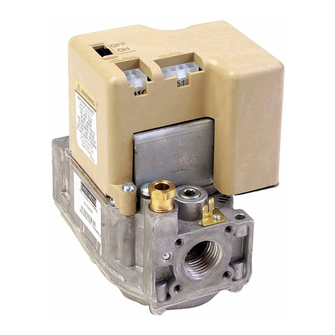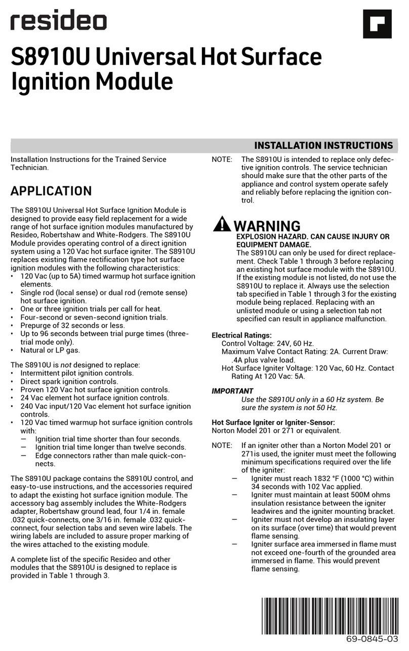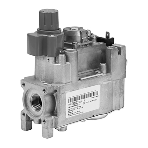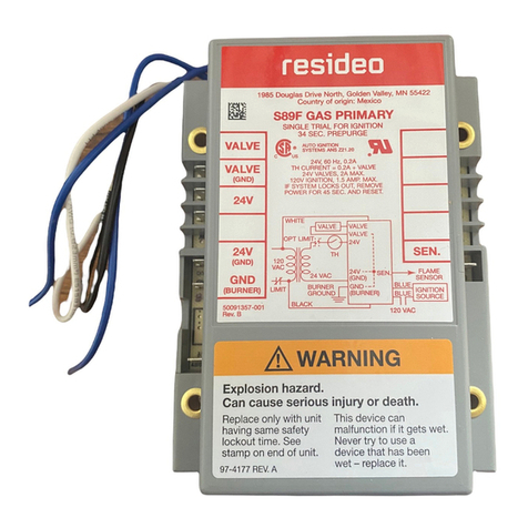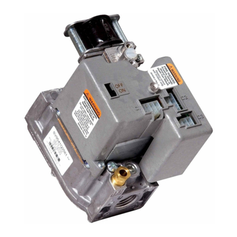
VR8205; VR4205 DIRECT IGNITION DUAL AUTOMATIC VALVE COMBINATION GAS CONTROLS
968-0049—03
Check Safety Lockout (Slow-opening
Controls Only)
1. With the system power off and the thermostat set to
call for heat, manually shut off the gas supply.
2. Energize ignitor control and start timing safety lockout
time. When spark ignition terminates, stop timing.
When using the VR8205H or VR4205H step-opening
control, the specified ignitor control safety lockout time
must exceed 8.5 seconds for system to function prop-
erly.
3. After spark cutoff, manually reopen gas control knob.
No gas should flow to the main burner.
4. Reset system by adjusting thermostat below room
temperature, waiting 30 seconds, and moving thermo-
stat setting up to call for heat. Normal ignition should
occur.
Check Safety Shutdown Performance
Fire or explosion hazard. Can cause property damage,
severe injury, or death.
Perform the safely shutdown test any time work is
done on a gas system.
NOTE: Read steps 1-7 below before starting and compare
to the safety shutdown or safety lockout tests rec-
ommended for the direct ignition (DI) module. Where
they differ, use the procedure recommended for the
module.
1. Turn off gas supply.
2. Set thermostat or controller above room temperature to
call for heat.
3. Watch for ignition spark or for glow at hot surface
igniter either immediately or following prepurge. See DI
module specifications.
4. Time the length of the igniter operation. See DI module
specifications.
5. After the module locks out, open manual gas cock and
make sure no gas is flowing to the burner.
6. Set the thermostat below room temperature and wait
one minute.
7. Operate system through one complete cycle to make
sure all controls operate properly.
MAINTENANCE
Regular preventive maintenance is important in applications
that place a heavy load on systems controls, such as in the
commercial cooking and agricultural and industrial
industries because:
• In many such applications, particularly commercial
cooking, the equipment operates 100,000-200,000 cycles
per year. Such heavy cycling can wear out the gas control
in one to two years.
• Exposure to water, dirt, chemicals and heat can damage
the gas control and shut down the control system.
The maintenance program should include regular checkout
of the gas control, see Startup and Checkout section, and the
control system as described in the appliance manufacturer
literature.
Maintenance frequency must be determined individually for
each application. Some considerations are:
• Cycling frequency. Appliances that may cycle 20,000
times annually should be checked monthly.
• Intermittent use. Appliances that are used seasonally
should be checked before shutdown and again before the
next use.
• Consequence of unexpected shutdown. Where the cost of
an unexpected shutdown would be high, the system
should be checked more often.
• Dusty, wet, or corrosive environment. Since these
environments can cause the gas control to deteriorate
more rapidly, the system should be checked more often.
Gas valves exposed to high ammonia conditions; i.e., those
used in greenhouses or animal barns, may fail in one or two
years. Contact your sales representative to request a gas
valve with corrosion resistant construction.
The gas control should be replaced if:
• It does not perform properly on checkout or
troubleshooting.
• The gas control knob is hard to turn.
• The gas controls is likely to have operated for more than
200,000 cycles.
OPERATION
The VR8205;VR4205 gas controls provide ON-OFF manual
control of gas flow. In the OFF position, gas flow to the main
burner is mechanically blocked. In the ON position, gas flows
to the main burner under control of the thermostat, the direct
ignition (DI) module, and the two automatic main valves.
System Operation With Module
When the thermostat calls for heat, the DI module is
energized. The module activates the first and second
automatic valves of the gas control, which allow gas to flow
to the main burner. At the same time, the DI module
generates a spark at the igniter-sensor to light the main
burner.
The second automatic valve diaphragm, controlled by the
servo pressure regulator, opens and adjusts gas flow as long
as the system is powered. The servo pressure regulator
monitors outlet pressure to provide an even flow of gas to the
main burner. Loss of power (thermostat satisfied)
deenergizes the DI module and closes the automatic valves.
The system is ready to return to normal service when power
is restored through the thermostat.
If the igniter-sensor stops detecting a flame at the main
burner, the trial for ignition is restarted. On DI modules with
lockout timers, the automatic valves are de-energized and
ignition stops after the lockout period. On modules without
lockout timers, the trial for ignition continues indefinitely.
If main burner flame is restarted successfully, operation
continues as described above. Gas control operation is
described in more detail below.

