RIB K500 User manual

K500
With functioning in hold-to-run man mode when the safety devices are failing.
Operator Power Supply Max gate weight Max Thrust Max torque Code
K500 230V 50/60Hz 500 kg / 1103 lbs 400 N 9,5 Nm AA33694

2
IMPORTANT SAFETY INSTRUCTIONS FOR THE
INSTALLATION
G
B
ATTENTION - FOR THE SAFETY OF PEOPLE IT IS IMPORTANT TO FOLLOW ALL THE
INSTRUCTIONS
KEEP THESE INSTRUCTIONS WITH CARE
1° - If it is not forecast in the electric gearcase, install a switch of magneto thermic type
upstream, (omni polar with minimum opening of the contacts of 3 mm) with a check of
conformity to the international standards. Such device must be protected against the
accidental lockup (for example by installing inside a locked board).
2° - For the section and the type of the cables RIB advices to use a cable of H05RN-F type
with 1,5 sqmm minimum section and, however, to keep to the IEC 364 and installation
standards in force in your country.
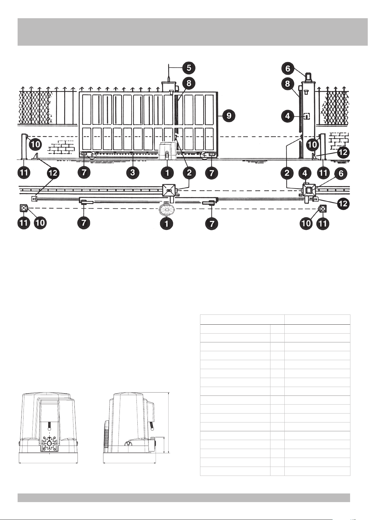
3° - Positioning of a possible couple of photoelectric cells: the radius of the photoelectric
cells must be at a height of no more than 70 cm from the ground and at a distance
not superior to 20 cm from the motion plane of the door. Their correct working must be
verified at the end of the installation in accordance with the point D.3.2 of the EN 12453
4° - To fulfill the limits set by EN 12453, and in case the peak force exceeds the normative
limit of 400 N it is necessary to have recourse to the active presence survey on the
whole height of the door (up to max 2,5 m) - The photoelectric cells, in this case, must
be applied in accordance with the point D.4.1 of the EN 12453.
N.B.: The earthing of the system is obligatory.
The data described in this handbook are purely a guide.
RIB reserves the right to change them in any moment.
Carry out the system in the respect of the standards and laws in force.
IMPORTANT SAFETY INSTRUCTIONS FOR THE INSTALLATION
ATTENTION - THE INCORRECT INSTALLATION CAN CAUSE SERIOUS DAMAGES
FOLLOW ALL INSTALLATION INSTRUCTIONS
1° - This handbook is exclusively addressed to the specialized personnel who knows
the constructive criteria and the protection devices against accidents for motorized
gates, doors and main doors (follow the standards and the laws in force).
2° - The installer will have to issue a handbook to the final user in accordance with the
EN 12635.
3° - Before proceeding with the installation, the installer must forecast the risks analysis
of the final automatized closing and the safety of the identified dangerous points
(Following the standards EN 12453).
4° - Before installing the motion motor, the installer must verify that the gate is in good
mechanical conditions and that it adequately opens and closes.
5° - The installer must install the member for the manual release at a height inferior to
1,8 m.
6° - The installer will have to remove possible impediments to the motorized motion of the
gate (eg. door bolts, sliding bolts, door locks etc.)
7° - The installer will permanently have to put the tags warning against the deflection on a
very visible point or near possible fixed controls.
8° - The wiring harness of the different electric components external to the operator (for
example photoelectric cells, flashlights etc.) must be carried out according to the EN
60204-1.
9° - The possible assembly of a keyboard for the manual control of the movement must be
done by positioning the keyboard so that the person operating it does not find himself
in a dangerous position; moreover, the risk of accidental activation of the buttons must
be reduced.
10° - Keep the automatism controls (push-button panel, remote control etc.) out of the
children way. Command device for operating the motor (a switch manually closed)
should be placed in area visible from the guided site and far from moving parts. It
should be placed at least at 1,5 m height.
11° - this appliance can be used by children aged from 8 years and above and persons with
reduced physical, sensory or mental capabilities or lack of experience and knowledge
if they have been given supervision or instruction concerning use of the appliance in
a safe way and understand the hazards involved
12° - children shall not play with the appliance
13° - cleaning and user maintenance shall not be made by children without supervision
14° - do not allow children to play with fixed controls. Keep remote controls away from
children
15° - Fixed command devices should be installed in a well visible way.
16° - Before carrying out any installation, regulation or maintenance operation of the
system, take off the voltage by operating on the special magneto thermic switch
connected upstream.
17° - At the end of the installation, the installer will have to make sure that the parts of the
door do not encumber streets or public sidewalks.
THE RIB COMPANY DOES NOT ACCEPT ANY RESPONSIBILITY for possible damages
caused by the non observance during the installation of the safety standards and of
the laws in force at present.

3
G
B
SYSTEM LAY-OUT
1 - K500 operating device
2 - External photocells
3 - Rack of Module 4
4 - Key selector
5 - Radio antenna
6 - Blinker
7 - Limit switch plate (cams)
8 - Mechanical strip
9 - Pneumatic strip or Fotocosta
10 - Internal Photocells
11 - Photocell columns
12 - Mechanical stops
TECHNICAL DATA K500
Max. leaf weight kg 500
Rack 4
EEC Power supply 230V~ 50Hz
Thrust force with constant turns
N 400
Max torque Nm 9,5
Motor capacity W 229
Power absorbed A 1,21
Capacitor µF 10
Normative cycles 230V/50Hz n° 12 - 30s/2s
Daily operations suggested n° 300
Service 60%
Guaranteed consecutive cycles
n° 25/5m
Grease COMLUBE LHITGREASE EP/GR.2
Weight of electroreducer kg 8
Noise db <70
Working temperature °C -10 ÷ +55
Protection IP 54
274 245
70,5 267
Measurements in mm
TECHNICAL FEATURES
Irreversible operating devices for sliding gates with a maximum weight of
500 kg / 4900 lbs.
The irreversibility of this operating device allows you to avoid using any electric lock
for an effective closing of the gate. The motor is protected by an heat probe, that
temporary interrupts the operating cycle in case of prolonged use.
1

4
INSTALLATION K500
CHECKING BEFORE THE INSTALLATION
!! THE GATE SHALL MOVE FRICTIONLESS !!
N.B.: Gate features must be uniformed with the standards and laws in force. The door/
gate can be automated only if it is in a good condition and its conditions comply with the
EN 12604 norm.
- The door/gate leaf does not have a pedestrian door. In the opposite case it is necessary
to take the appropriate steps, in accordance with EN 12453 norm (for instance; by
preventing the operation of the motor when the pedestrian door is opened, by installing
a safety microswitch connected with the control panel).
- Besides the electrical or mechanical limit switches available on the operators, there must
be, on both ends of the installation, a fixed mechanical stopper which stop the gate in
the unlikely event of ill functioning of limit swithces on the operators. For this reason the
fixed mechanical stopper must be of an adeguate size to withstand the static and kinetic
forces generated by the gate (12) (fig. 2).
- Gate columns shall have anti-derailment guides on their top (fig. 3), to avoid the
unintentional gate release.
N.B.: Remove mechanical stops like the one in fig. 3.
No mechanical stops shall be on top of the gate, since these mechanical stops are not
safe enough.
Parts to install according to EN 12453 standard
COMMAND TYPE
USE OF THE SHUTTER
Skilled persons
(out of public area*)
Skilled persons
(public area)
Not skilled
persons
Hold-to-run operation A B Not possible
Impulsive - in sight
(e.g. push-button) C or E C or E C and D, or E
impulsive - out of sight
(e.g. remote) C or E C and D, or E C and D, or E
automatic C and D, or E C and D, or E C and D, or E
* a typical example are those doors which do not have access to any public way
A: Hold-to-run operation made by push-button ex: code ACG2013
B: Hold-to-run operation made by key selector ex: code ACG1010
C: Adjustable power of the motor or photocells to respect impact forces as indicated in
Annex A
D: Safety strips and/or other additional devices to reduce the probability of contact with
the door.
E: Devices installed in such a way that a person can not be touched by the door.
RELEASE
To operated after the power supply to the motor has been interrupted.
In order to work manually on the gate, you just need to insert the fitting key and rotate it
3 times counterclockwise (fig. 4).
In order to carry out the manual operation of the gate leaf the followings must be checked:
- That the gate is endowed with appropriate handles;
- That these appropriate handles are placed so to avoid safety risks for the operator;
- That the physical effort necessary to move the gate leaf should not be higher than 225
N, for doors/gates for private dwellings, and, 390 N for doors/gates for commercial and
industrial sites (values indicated in 5.4.5 of the EN 12453 norm).
2
3
4
G
B

5
MOTOR AND RACK FITTING
The rack shall be fitted over the motor support, at a certain distance from it.
Its height can be adjusted thanks to the holes In the rack.
The height is adjusted to prevent the gate from resting on the driving gear of the K as it
moves (Fig. 5).
To fix the rack on the gate, drill some Ø 5 mm holes and thread them using an M6
screw tap.
The driving gear needs some 1 mm clearance from the rack.
LIMIT SWITCH FITTING
In order to determine the travel of the moving part, place two cams at the ends
of the rack (Fig. 6).
Move the cams on the rack teeth to adjust their opening and closing travel.
To fix the cams to the rack, tighten the screws issued.
N.B: In addition to the electric stop cams mentioned above, you must also install strong
mechanical stops preventing the gate from sliding out of the top guides.
MAINTENANCE
To be carried out exclusively by skilled persons after the power supply to the
motor has been interrupted.
Periodically, when the gate is standstill, clean and keep the guide free from stones and
dirt.
5
6
G
B

6

7
K500
Codice Denominazione Particolare
ACG1071 Chiave di sblocco
BA01045 Serie access. cilind. K500
BA10086 Carter K500 completo
BA10087 Ingranaggio traino K500
CAL1155 Corona elicoidale
CAL1166 Carcassina + campana motore K500
CCA1179 Perno cerniera scatola QE
CCA1324 Camme finecorsa DX
CCA1325 Camme finecorsa SX
CCM6005ZZ Cuscinetto motore 6005ZZ
CCM6202ZZ Cuscinetto motore 6202 ZZ
CEL1071 Passacavo PG9
CEL1074 Passacavo PG16
CEL1350 Microswitch a rotella
CEL1425 Condensatore 10µF con cavetto
CEL1520 Supporto sella
CEL1529 Cavetto terra
CME1131 Albero di traino
CME1132 Perno sblocco
CMO1318 Rotore con albero K500
CMO1345 Statore K500 230/50-60 1P
CMO1346 Statore K500 120/60 1P
CPL1202 Sfera per molla
CPL1203 Flangia finecorsa
CPL1206 Boccola
CPL1236 Scatola QE
CPL1237 Coperchio scatola QE
CTC1090 Paraolio 20x30x5
CTC1331 Molla finecorsa Inox
CTC1205 Molla per sblocco
CTC1214 Spina CIL 8x32 non temprata
CTC1293 Spina CIL10x55
CTC1303 Anello di tenuta OR_158
CTC1307 Anello di tenuta OR2037
CTC1404 Paraolio 25x40x7
CVA1060 Guarnizione K
DAC29x95 Vite aut.TC.CR. 2.9x9.5 ZINCAT
DAC39x95 Vite aut.TC.CR 3.9x9.5 DIN798
DAC35x95 Vite aut.TC.CR 3.5x9.5
DAC4X10 Vite Autom. TC CR 4x10 TRIL.UNI
DAC42x16 Vite auto. TC.CR. 4.2x16
DAC5x10 Vite Autom. TC CR 5x10 TRIL UNI8112
DAE55x16 Vite aut. TE 5.5x16 P.Tronca Z
DDD6MA Dado autob. 6MA ALTO
DDMM8 Dado 8MA medio UNI5588
DDMM3Z Dado 3MA medio UNI5588
DRD4 Rond. dent. D=4 piano DIN6798
DRL8x26 Rond. piana 8.5x26x2.5
DSB6x25 Vite TSPEI 6x25 UNI5933
DSC3x20Z Vite TSP.CR 3x20
DST8x45 Grano M8x45 UNI5927
DTB63x25 Vite TCEI 6.3x25 AUTOF.ZINC.
DTE8x40 Vite TE 8x40 UNI5739

Cod. CVA2137 - 01032018 - Rev. 01
Declaration of incorporation for partly completed machinery - Machinery Directive 2006/42/EC, Annex II., B
R.I.B. S.r.l. - Via Matteotti, 162 - 25014 Castenedolo - Brescia - Italy
Apparatus model : K500 Object of the declaration :
The following essential requirements of the Machinery Directive (2006/42/EC) are abided by and applied:
· The relevant technical documentation is compiled in accordance with Part B of Annex VII; such documentation, or parts of it, will be sent by post or by
electronic means, in response to a motivated request received from the qualified national authorities.
· This almost complete-machinery is conformed with the provisions of these others EC directives: Directives 2014/30/UE and 2014/35/UE.
· All relevant essential requirements as given in Annex I of the EU Directive 2006/42/EC have been applied to the product. Compliance with the cited
harmonized standards provides presumption of conformity with the specified essential requirements of the Directive covered by those Standards or
parts thereof.
WARNING: Other requirements and other EU Directives may be applicable to the products falling within the scope of this Declaration
The object of the declaration described above is in conformity with the relevant Union harmonisation legislation:
- This product can not work alone and was designed to be fitted into a system made up of various other elements. Hence, it falls within Article 6,
Paragraph 2 of the EC-Directive 2006/42 (Machines) and following modifications, to which respect we point out the ban on its putting into service
before being found compliant with what is provided by the Directive.
(Bosio Stefano - Legal Representative)
EN 12453:2017
EN 12635:2002+A1:2008
EN 12978:2003+A1:2009
EN 13241-1:2016
EN 13849-1:2015 (pl b)
EN 13849-2:2012
EN 55014-1:2017
EN 55014-2:2016
EN 60335-1:2016
EN 60335-2-103:2015
EN 61000-3-2:2014
EN 61000-3-3:2013
EN 61000-6-1:2007
EN 61000-6-2:2005
EN 61000-6-3:2007+A1:2011
EN 61000-6-4:2007+A1:2011
Castenedolo, 01-03-2018
· This product has been completely developed and built in Italy
AUTOMATISMI PER CANCELLI
AUTOMATIC ENTRY SYSTEMS
Other manuals for K500
3
Table of contents
Other RIB Gate Opener manuals
Popular Gate Opener manuals by other brands

tau
tau TSKY-B Use and maintenance manual

CAME
CAME FA40230CB installation manual

Chamberlain
Chamberlain LiftMaster Professional SW420 Installation

Estate Swing
Estate Swing Classic Series instruction manual

CAME
CAME ZC3C installation manual

Nortek Security & Control
Nortek Security & Control MIGHTY MULE MM272 installation manual

Chamberlain
Chamberlain ART300-24MB instructions

fadini
fadini MEC 200 installation manual

Roger Technology
Roger Technology H21 Series INSTRUCTIONS AND RECOMMENDATIONS FOR THE INSTALLER

Proteco
Proteco MOVER Installation and use manual

BFT
BFT CELLULA 180 Operating and installation instructions

BFT
BFT P7 Installation and user manual