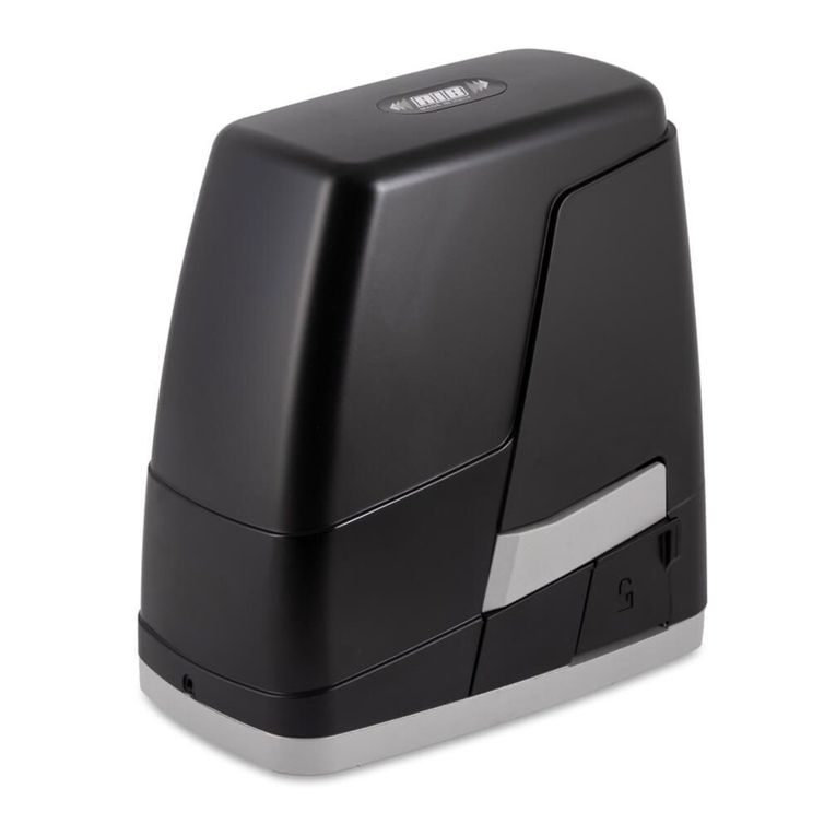
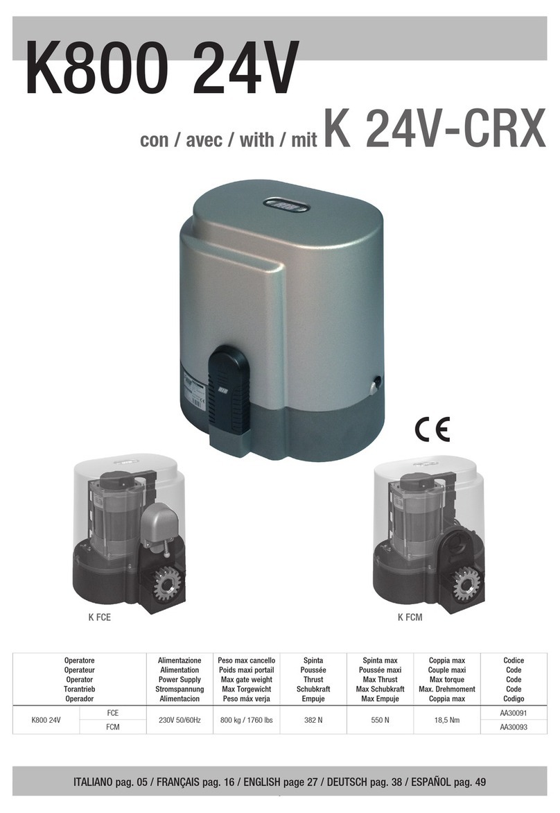
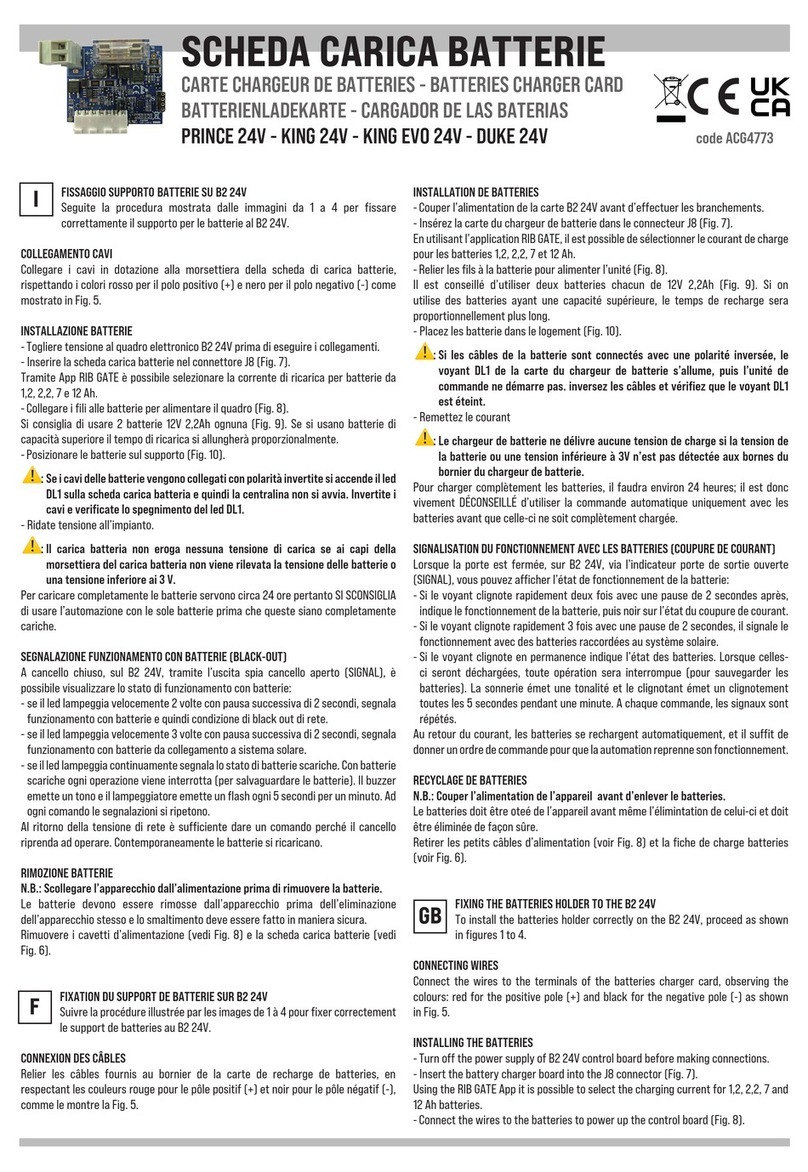
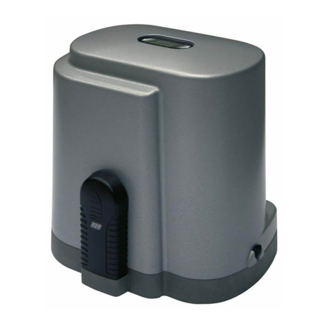
RIB KING 24V User manual

KKIINNGG2244VV
Operatore
Operateur
Operator
Torantrieb
Operador
Alimentazione
Alimentation
Power Supply
Stromspannung
Alimentacion
Forza max di spinta
Force maxi de poussée
Thrust force
Max. Schubkraft
Fuerza max de empuje
codice
code
code
code
codigo
KING 24V 24Vdc N 1800 AA14028
Peso max cancello
Poids maxi portail
Max gate weight
Max Torgewicht
Peso máx verja
400 kg / 880 lbs
KING 24V L 24Vdc N 1800 AA14029
500 kg / 1100 lbs
ITALIANO pag. 05 / FRANÇAIS pag. 16 / ENGLISH page 27 / DEUTSCH pag. 38 / ESPAÑOL pag. 49
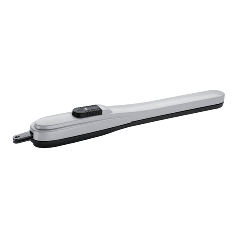
OPERATORE IRREVERSIBILE PER CANCELLI A BATTENTE
OPERATEUR IRREVERSIBLE POUR PORTAILS À BATTANT
IRREVERSIBLE OPERATOR FOR LEAF GATES
TORANTRIEBE FÜR FLÜGELTORE
OPERADOR IRREVERSIBLE PARA CANCELAS DE BATIENTE

2
2
CONSERVARE CON CURA QUESTE ISTRUZIONI
1° - Se non è previsto nel quadro elettronico, installare a monte della
medesima un'interruttore di tipo magnetotermico (onnipolare con
apertura minima dei contatti pari a 3mm) che riporti un marchio di
conformità alle normative internazionali. Tale dispositivo deve
essere protetto contro la richiusura accidentale (ad esempio
installandolo dentro quadro chiuso a chiave).
2° - Per la sezione ed il tipo dei cavi la RIB consiglia di utilizzare un
cavo di tipo H05RN-F con sezione minima di 1,5mm2e comunque
di attenersi alla norma IEC 364 e alle norme di installazione
vigenti nel proprio Paese.
3° - Posizionamento di un’eventuale coppia di fotocellule: Il raggio
delle fotocellule deve essere ad un’altezza non superiore a 70 cm
dal suolo e ad una distanza dal piano di movimento dell’anta non
superiore a 20 cm. Il loro corretto funzionamento deve essere
verificato a fine installazione in accordo al punto 7.2.1 della EN
12445.
4° - Per il soddisfacimento dei limiti imposti dalla EN 12453, se la
forza di picco supera il limite normativo di 400 N è necessario
ricorrere alla rilevazione di presenza attiva sull’intera altezza del
cancello (fino a 2,5m max) - Le fotocellule in questo caso sono da
applicare all’esterno tra le colonne ed all’interno per tutta la corsa
della parte mobile ogni 60÷70cm per tutta l’altezza delle colonne
del cancello fino ad un massimo di 2,5m (EN 12445 punto
7.3.2.1) - es. colonne alte 2,2m => 6 coppie di fotocellule - 3
interne e 3 esterne (meglio se dotate di sincronismo - 6 FIT
SYNCRO con 2 TX SYNCRO).
N.B.:É obbligatoria la messa a terra dell'impianto
I dati descritti nel presente manuale sono puramente indicativi.
La RIB si riserva di modificarli in qualsiasi momento.
Realizzare l’impianto in ottemperanza alle norme ed alle leggi vigenti.
SEGUIRE TUTTE LE ISTRUZIONI DI INSTALLAZIONE
1° - Questo libretto d'istruzioni è rivolto esclusivamente a del
personale specializzato che sia a conoscenza dei criteri
costruttivi e dei dispositivi di protezione contro gli infortuni per i
cancelli, le porte e i portoni motorizzati (attenersi alle norme e alle
leggi vigenti).
2° - L’installatore dovrà rilasciare all’utente finale un libretto di
istruzioni in accordo alla EN 12635.
3° - L’installatore prima di procedere con l’installazione deve
prevedere l’analisi dei rischi della chiusura automatizzata finale e
la messa in sicurezza dei punti pericolosi identificati (seguendo le
norme EN 12453/EN 12445).
4° - Il cablaggio dei vari componenti elettrici esterni all’operatore (ad
esempio fotocellule, lampeggianti, ecc.) deve essere effettuato
secondo la EN 60204-1 e le modifiche a questa apportate dal
punto 5.2.2 della EN 12453.
5° - L’eventuale montaggio di una pulsantiera per il comando manuale
del movimento deve essere fatto posizionando la pulsantiera in
modo che chi la aziona non si trovi in posizione pericolosa; inoltre
si dovrà fare in modo che sia ridotto il rischio di azionamento
accidentale dei pulsanti.
6° - Tenete i comandi dell'automatismo (pulsantiera, telecomando
etc.) fuori dalla portata dei bambini. I comandi devono essere
posti ad un’altezza minima di 1,5m dal suolo e fuori dal raggio
d’azione delle parti mobili.
7° - Prima di eseguire qualsiasi operazione di installazione,
regolazione, manutenzione dell’impianto, togliere la tensione
agendo sull’apposito interruttore magnetotermico collegato a
monte dello stesso.
LA DITTA RIB NON ACCETTA NESSUNA RESPONSABILITÀ per
eventuali danni provocati dalla mancata osservanza nell'installazione
delle norme di sicurezza e delle leggi attualmente in vigore.
ISTRUZIONI DI SICUREZZA IMPORTANTI
PER L’INSTALLAZIONE
- ATTENZIONE -
PER LA SICUREZZA DELLE PERSONE É IMPORTANTE
CHE VENGANO SEGUITE TUTTE LE ISTRUZIONI
CONSERVER SOIGNEUSEMENT CES INSTRUCTIONS
1° - Si la centrale électrique ne dispose d'aucun interrupteur, il faut en
installer un de type magnétothermique en amont de cette
dernière (omnipolaire avec ouverture minimale des contacts
correspondant à 3mm); la marque de cet interrupteur devra être
en conformité avec les normes internationales. Ce dispositif doit
être protégé contre toute remise en fonction accidentelle (ex. en
l’installant dans un coffre fermant à clé).
2° - En ce qui concerne la section et le type des câbles, le conseil de
la RIB est celui d'utiliser un câble de type H05RN-F présentant
une section minimale de 1,5mm2et, quoi qu'il en soit, de se
conformer à la norme IEC 364, ainsi qu'aux normes d'installation
en vigueur dans le pays de destination.
3° - Positionnement d’un éventuel jeu de photocellules : le faisceau
des photocellules ne doit pas être à une hauteur supérieure à 70
cm du sol et 20 cm du bord du vantail. Leur correct effectivité
fonctionnement doit être vérifié terminant l’installation, selon le
point de la 7.2.1 de la EN 12445.
4° - Afin de satisfaire aux limites imposées par la norme EN 12453, si
la force d’impact dépasse la limite de 400N, il sera nécessaire de
détecter une présence sur la hauteur totale du portail (jusqu'à un
maximum de 2,5m) - Les cellules photo-électriques dans ce cas-
ci doivent être s'appliquent extérieurement entre les colums et
intérieurement pour toute la course de la pièce de mobil chaque
60÷70cm pour toute la taille de la colonne de la porte jusqu'à un
maximum de 2,5m (EN 12445 point 7.3.2.1) - exemple: taille 2,2m
de colonne = > 6 copies des cellules photo-électriques - 3
internes et 3 externes (meilleur si complet du dispositif de
syncronism - FIT SYNCRO avec TX SYNCRO).
N.B.:La mise à terre de l'installation est obligatoire.
Les données figurant dans le présent manuel sont fournies à titre
purement indicatif. La RIB se réserve le droit de les modifier à tout
moment, sans aucun préavis. Effectuer l'installation en conformité
avec les normes et les lois en vigueur.
SUIVRE TOUTES LES INSTRUCTIONS D’INSTALLATION
1° - Ce livret d’instructions est adressé exclusivement à un
personnel spécialisé qui connaît les critères de construction et
les dispositifs de protection contre les accidents concernant les
portails, les portes et les grandes portes motorisés (s’en tenir aux
normes et aux lois en vigueur).
2° - L’installateur devra délivrer à l’utilisateur final un livret
d’instruction en accord à la EN 12635.
3° - L’installateur avant de procéder à l’installation, doit prévoir
l’analyse des risques de la fermeture automatisée finale et la mise
en sécurité des points identifiés dangereux (en suivant les
normes EN 12453/EN 12445).
4° - Le câblage des divers composants électriques externes à
l’opérateur (par exemple photocellules, clignotants, etc) doit être
effectué selon la EN 60204-1 et les modifications apportées à
celle-ci dans le point 5.2.2 de la EN 12453.
5° - Le montage éventuel d’un tableau pour la commande manuelle
du mouvement doit être fait en positionnant le tableau de façon à
ce que la personne qui l’actionne ne se trouve pas en position de
danger ; de plus, il faudra faire en sorte que le risque
d’actionnement accidentel des boutons soit réduit.
6° - Tenir les commandes de l’automatisme (tableau, télécommande,
etc) hors de portée des enfants. Les commandes doivent être
placées à une hauteur minimum de 1,5 m du sol et hors du rayon
d’action des parties mobiles.
7° - Avant l’exécution de toute opération d’installation, de réglage,
d’entretien de l’installation, couper le courant en agissant sur
l’interrupteur magnétothermique à cet effet, branché en amont de
l’installation.
LA SOCIETE RIB N’ACCEPTE AUCUNE RESPONSABILITE pour
d’éventuels dommages provoqués par la non-observation dans
l’installation, des normes de sécurité et des lois actuellement en
vigueur.
INSTRUCTIONS DE SECURITE
IMPORTANTES POUR L’INSTALLATION
- ATTENTION -
POUR LA SECURITE DES PERSONNES IL EST IMPORTANT
QUE TOUTES LES INSTRUCTIONS SOIENT SUIVIES
IIFF

3
3
KEEP THESE INSTRUCTIONS WITH CARE
1° - Install a thermal magnetic switch (omnipolar, with a minimum
contact opening of 3 mm) before the control board, in case this is
not provided with it. The switch shall be guaranteed by a mark of
compliance with international standards. Such a device must be
protected against accidental closing (e.g. Installing it inside the
control panel key locked container).
2° - As far as the cable section and the cable kind are concerned, RIB
suggests to use an H05RN-F cable, with a minimum section of
1,5mm2, and to follow, In any case, the IEC 364 standard and
Installation regulations In force In your Country.
3° - Positioning of an eventual pair of photocells: The beam of the
photocells must be at an height not above the 70 cm from the
ground, and, should not be more than 20 cm away from the axis
of operation of the gate (Sliding track for sliding gate or door, and
the hinges for the swing gate). In accordance with the point 7.2.1
of EN 12445 their correct functioning must be checked once the
whole installation has been completed.
4° - In order to comply with the limits defined by the EN 12453 norm,
if the peak force is higher than the limit of 400N set by the norm,
it is necessary to use an active obstacle detection system on the
whole height of the gate (up to a maximum of 2,5m) - The
photocells in this case must be apply externally between the
colums and internally for all the race of the mobil part every
60÷70cm for all the height of the column of the gate up to a
maximum of 2,5m (EN 12445 point 7.3.2.1). example: column
height 2,2m => 6 copies of photocells - 3 internal and 3 external
(better if complete of syncronism feature - FIT SYNCRO with TX
SYNCRO).
N.B.: The system must be grounded
Data described by this manual are only Indicative and RIB reserves to
modify them at any time. Install the system complying with current
standards and regulations.
FOLLOW ALL INSTALLATION INSTRUCTIONS
1° - This handbook is exclusively addressed to the specialized
personnel who knows the constructive criteria and the protection
devices against the accidents for motorized gates, doors and
main doors (follow the standards and the laws in force).
2° - The installer will have to issue to the final user a handbook in
accordance with the EN 12635.
3° - Before proceeding with the installation, the installer must forecast
the risks analysis of the final automatized closing and the safety
of the identified dangerous points (following the standards EN
12453/EN 12445).
4° - The wiring harness of the different electric components external
to the operator (for example photoelectric cells, flashlights etc.)
must be carried out according to the EN 60204-1 and the
modifications to it done in the point 5.2.2 of the EN 12453.
5° - The possible assembly of a keyboard for the manual control of the
movement must be done by positioning the keyboard so that the
person operating it does not find himself in a dangerous position;
moreover, the risk of accidental activation of the buttons must be
reduced.
6° - Keep the automatism controls (push-button panel, remote control
etc.) out of the children way. The controls must be placed at a
minimum height of 1,5m from the ground and outside the range of
the mobile parts.
7° - Before carrying out any installation, regulation or maintenance
operation of the system, take off the voltage by operating on the
special magnetothermic switch connected upstream it.
THE RIB COMPANY DOES NOT ACCEPT ANY RESPONSIBILITY
for possible damages caused by the non observance during the
installation of the safety standards and of the laws in force at present.
IMPORTANT SAFETY INSTRUCTIONS FOR THE
INSTALLATION
- ATTENTION -
FOR THE SAFETY OF THE PEOPLE IT IS IMPORTANT
TO FOLLOW ALL THE INSTRUCTIONS.
INSTALLATIONSVORSCHRIFTEN BEACHTET WERDEN
1° - Wenn nicht bereits an der elektrischen Schaltzentrale
vorgesehen, muss vor der Schaltzentrale ein
thermomagnetischer Schalter installiert werden (omnipolar, mit
einer minimalen Kontaktöffnung von 3 mm), der ein von den
internationalen Normen anerkanntes Konformitätszeichen besitzt.
Solch ein Geraet muss vor Vandalismus geschuetzt
werden(z.B.mit einen Schluesselkatsten in einem
Panzergehaeuse)
2° - RIB empfiehlt den Kabeltyp H05RN-F mit einem minimalen
Querschnitt von 1,5mm2generell sollten die Normative IEC 364
und alle anderen geltenden Montagenormen des
Bestimmungslandes eingehalten werden.
3°- Position des ersten paar Fotozellen: Der sollten nicht hoeher als
70cm vom Boden sein, und sollte nicht mehr als 20 cm entfernt
von der Achse des Tores sitzen (das gilt fuer Schiebe und
Drehtore). In Übereinstimmung mit dem Punkt 7.2.1 der EN 12445
Norm, ihr korrektes Funktionieren muß einmal überprüft werden.
4°- In Einklang mit der Norm EN12453, ist es bei Toren notwendig
eine komplette Sicherheitslieiste zu installieren, bei denen mehr
als 400N Kraft aufgewand werden muessen, um das Tor zum
anhalten zu bringen (Maximum von 2,5m anwenden) - Die
Fotozellen müssen in diesem Fall sein beantragen außen
zwischen den colums und innerlich das ganzes Rennen des mobil
Teils jede 60÷70cm für die ganze Höhe der Spalte des Gatters bis
zu einem Maximum von 2,5m - EN 12445 Punkt 7.3.2.1). Beispiel:
Spalte Höhe 2,2m => 6 Kopien von Fotozellen - 3 intern und 3
extern (besser, wenn komplett von der syncronism Eigenschaft -
FIT SYNCRO mit TX SYNCRO).
ANMERKUNG: Die Erdung der Anlage ist obligatorisch
Die in diesem Handbuch aufgeführten Daten sind ausschließlich empfohlene
Werte. RIB behält sich das Recht vor, das Produkt zu jedem Zeitpunkt zu
modifizieren. Die Anlage muss in Übereinstimmung mit den gültigen Normen
und Gesetzen montiert werden.
ALLE INSTALLATIONSANLEITUNGEN BEFOLGEN
1° - Diese Betriebsanleitung dient ausschließlich dem
Fachpersonal, welche die Konstruktionskriterien und die
Sicherheits-Vorschriften gegen Unfälle für Tore, Türen und
automatische Tore kennt (geltende Normen und Gesetze
beachten und befolgen).
2° - Der Monteur muss dem Endkunde eine Betriebsanleitung in
Übereinkunft der EN12635 überreichen.
3° - Vor der Installierung muss für die automatische Schließung und
zur Sicherheitsgewährung der identifizierten kritischen Punkte,
eine Risiko Analyse vorgenommen werden mit der
entsprechenden Behebung der identifizierten, gefährlichen
Punkte. (die Normen EN 12453/EN 12445 befolgend).
4° - Die Verkabelung der verschiedenen externen elektrischen
Komponenten zum Operator (z.B. Fotozellen, Blinker etc.) muss
nach EN 60204-1 ausgeführt werden, Änderungen davon nach
Punkt 5.2.2 der EN 12453.
5° - Die eventuelle Montage einer Schalttafel für den manuellen
Bewegungsbefehl muss so angebracht werden, dass der
Benutzer sich nicht in einer Gefahrenzone befindet, und dass,
das Risiko einer zufälligen nicht gewollten Aktivierung von
Schaltern gering ist.
6° - Alle Steuerungselemente (Schalttafel, Fernbedienung etc.)
gehören nicht in Reichweite von Kindern. Die Kommandos
müssen min. 1,5 m ab Boden und außerhalb des
Aktionsbereiches der mobilen Teile angebracht werden.
7° - Vor jeglichem Eingriff, sei es Installation, Regulation oder
Wartung der Anlage, muss vorher die Stromzufuhr unterbrochen
werden, den dafür bestimmten Magnetthermo-Schalter drücken,
der am Eingang der Anlage installiert ist.
DIE FIRMA RIB ÜBERNIMMT KEINE VERANTWORTUNG für eventuelle
Schäden, die entstehen können, wenn die Installierungsvorschriften die den
gültigen Sicherheitsnormen entsprechen, nicht eingehalten werden.
WICHTIGE SICHERHEITS ANLEITUNGEN FÜR DIE
INSTALLATIONEN
- ACHTUNG -
FÜR DIE SICHERHEIT DER PERSONEN IST ES WICHTIG,
DASS ALLE ANWEISUNGEN GENAU AUSGEFÜHRT WERDEN
GG
BBD
D
4
4
CONSERVAR CUIDADOSAMENTE ESTAS INSTRUCCIONES
1° - En el caso de que no sea previsto en la central eléctrica, instalar
antes de la misma, un interruptor de tipo magnetotérmico
(omnipolar con una abertura mínima de los contactos de 3mm)
que dé un sello de conformidad con las normas internacionales.
Este dispositivo tiene que estar protegido contra cierres
accidentales (por ejemplo instalándolo dentro de un panel
cerrado a llave).
2° - Para la sección y el tipo de los cables, la RIB aconseja utilizar
cables de tipo H05RN-F con sección mínima de 1,5mm2e
igualmente atenerse a la norma IEC 364 y a las normas de
instalación del propio País.
3° - Posicionamiento eventual de un par de fotocélulas. El rayo de las
fotocélulas no debe estar a más de 70 cm de altura desde el
suelo y a una distancia de la superficie de movimiento de la
puerta, no superior a 20 cm. El correcto funcionamiento tiene que
ser controlado al final de la instalación de acuerdo con el punto
7.2.1 de la EN 12445.
4° - Para satisfascer los límites impuestos por la EN 12453, si la
fuerza de punta supera el límite normativo de 400 N, es necesario
recurrir al control de presencia activa en toda la altura de la
puerta (hasta a 2,5m max). Las fotocélulas en este caso se tienen
que colocar en el exterior entre las columnas y en el interior por
todo el recorrido de la parte móvil cada 60÷70cm en toda la altura
de las columnas de la cancela hasta un máximo de 2,5m (EN
12445 punto 7.3.2.1) - es. columnas altas de 2,2m => 6 par de
fotocélulas - 3 internas y 3 externas (mejor si están provistas de
sincronismo - 6 FIT SYNCRO con 2 TX SYNCRO).
PS.:Es obligatorio la puesta a tierra del sistema.
Los datos descritos en el presente manual son sólamente indicativos.
La RIB se reserva de modificarlos en cualquier momento.
Realizar el sistema respetando las normas y las leyes vigentes.
SEGUIR TODAS LAS INSTRUCCIONES DE INSTALACIÓN
1° - Este manual de instrucciones está exclusivamente dirigido a
personal especializado que conozca los criterios de
construcción y de los dispositivos de protección contra
accidentes con cancelas, puertas y portales motorizados
(atenerse a las normas y a las leyes vigentes).
2° - El instalador tendrá que dar al utilizador final un manual de
instrucciones de acuerdo con la EN 12635.
3° - El instalador antes de proceder con la instalación tiene que hacer
una analisis de los riesgos del cierre automatizado final y la puesta
en seguridad de los puntos identificados como peligrosos
(siguiendo las normas EN 12453 / EN 12445).
4° - El cablaje de los varios componentes eléctricos externos al
operador (por ejemplo fotocélulas, los intermitentes, etc) tiene que
ser efectuado según la EN 60204-1 y a las modificas sucesivas
aportadas por el punto 5.2.2 della EN 12453.
5° - El eventual montaje de un panel de mandos para la gestión del
movimiento manual tiene que ser efectuado posicionando el
panel en modo que quién lo accione no se encuentre en una
posición peligrosa; además se tiene que hacer en modo que el
riesgo de accionamiento accidental de los pulsadores sea
mínimo.
6° -Tener los mandos del automatismo (panel de mandos, mando a
distancia, etc.) lejos del alcance de los niños. Los mandos tienen
que ser puestoa una altura mínima de 1,5m del suelo y fuera del
radio de acción de las partes móviles.
7° - Antes de ejecutar cualquier operación de instalación, ajuste o
mantenimiento del sistema, quitar la corriente accionando el
respectivo interruptor magnetotérmico conectado antes del
mismo.
LA EMPRESA RIB NO ES RESPONSABLE por eventuales daños
provocados por la falta de respeto de las normas de seguridad,
durante la instalación y de las leyes actualmente vigentes.
IMPORTANTES INSTRUCCIONES DE SEGURIDAD
PARA LA INSTALACIÓN
- CUIDADO -
UNA INCORRECTA INSTALACIÓN PUEDE CAUSAR
GRAVES DAÑOS
EE
SS

Misure in mm
KING L L=1020 L1=945 L2=470
KING L=888 L1=815 L2=340
5
5
LAYOUT IMPIANTO
1 - Operatore KING 24V
2 - Antenna radio
3 - Lampeggiatore
4 - Selettore a chiave
5 - Fotocellule esterne
CARATTERISTICHE TECNICHE
KING 24V è un operatore irreversibile utilizzato per
movimentare cancelli a battente con ante lunghe fino a 4,5 m
(Fig. 1).
KING 24V è stato concepito per funzionare senza finecorsa
elettrici, ma solo meccanici.
II
❺
❹
❶❶❺❹
❷❸
CARATTERISTICHE
TECNICHE
Lunghezza max. anta
Peso max anta
Corsa max di traino
Tempo medio di apertura
Velocità di traino
Forza max di spinta
Alimentazione e frequenza CEE
Potenza motore
Assorbimento
Cicli consigliati al giorno
Servizio
Cicli consecutivi garantiti
Lubrificazione a grasso
Peso motore
Rumorosità
Volume
Temperatura di lavoro
Grado di protezione
m 3,5* 4,5*
kg 400 500
mm 345** 475**
s. 14÷27 29÷38
m/s. 0,0125
N 1800
24V
W118
A 5,4
n° 150
90%
n° 200/14s
Bechem - RHUS 550
kg 10 14
db <70
m30,0184 0,0211
°C -10 ÷ +55°C
IP 447
** Con fermo meccanico incorporato che interviene durante l'apertura.
Se si utilizza anche il fermo meccanico che interviene durante la
chiusura, opzionale, la corsa massima di traino si riduce di 50 mm.
KING 24V KING 24V L
1
21
2
1
2
Collegamento
Motore
Other manuals for KING 24V
1
This manual suits for next models
1
Table of contents
Languages:
Other RIB Gate Opener manuals
Popular Gate Opener manuals by other brands

Nortek Security & Control
Nortek Security & Control Mighty Mule HD272 installation manual

tousek
tousek TURN 10 Installation and operating instructions

SOMFY
SOMFY AXOVIA 220B RTS installation instructions

Nice HySecurity
Nice HySecurity CBOX1050 Installation and programming manual

CAME
CAME FROG-PM4 installation manual

Aprimatic
Aprimatic ONDA 500 installation instructions