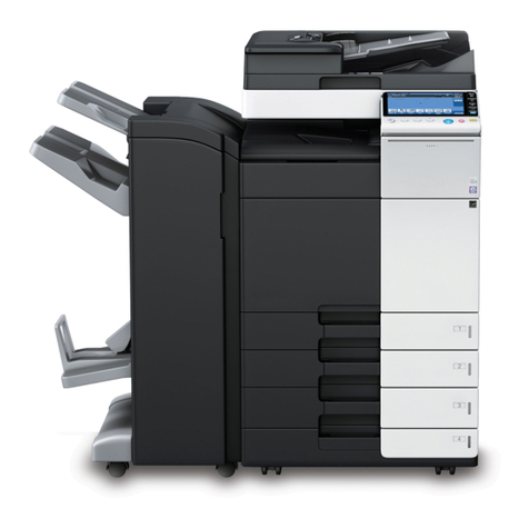
Ricoh FT6645 User manual

SECTION 1
OVERALL MACHINE
INFORMATION

1. SPECIFICATIONS
Configuration: Console
Copy Process: Dry electrostatic transfer system
Toner Supply Control: Fuzzy Control
Photoconductor: OPC drum
Originals: Sheet/Book
Original Size: Maximum A3/11" x 17"
Original Alignment: Left rear corner
Copy Paper Size: Maximum A3/11" x 17"
Minimum A5/51/2" x 81/2" (Tray)
B5/81/2" x 11" (1.5K LCT)
A6/51/2" x 81/2" (By-pass)
Duplex Copying: Maximum A3/11" x 17"
Minimum A5/51/2" x 81/2" (sideways)
Copy Paper Weight: Paper tray: 52 ~ 128 g/m2, 14 ~ 34 lb
Bypass feed table: 52 ~ 157 g/m2, 14 ~ 42 lb
Duplex copying: 64 ~ 104 g/m2, 17 ~ 24 lb
Reproduction Ratios: 4 Enlargement and 6 Reduction
A4/A3 Version LT/LDG Version
Enlargement 200%
141%
122%
115%
200%
155%
129%
121%
Full Size 100% 100%
Reduction 93%
82%
75%
71%
65%
50%
93%
85%
77%
74%
65%
50%
Overall
Information
23 April 1993 SPECIFICATIONS
1-1

Power Source: 115V,60Hz,more than20A(for N.A)
220~ 240V, 50Hz/60Hz,more than10A(for EU
and AA)
Power Consumption:A095 and A096copiers
Copieronly Full system*
Warm-up 0.9 kVA 0.9 kVA
Stand-by 0.25 kVA 0.25 kVA
Copying 1.2 kVA 1.3 kVA
Maximum 1.45 kVA 1.5 kVA
*Full System:
•Mainframewith dual jobfeeder, compact
sorter stapler and3,500-sheetlargecapacity
tray
•Mainframewith dual jobfeeder, floor type
sorter stapler and3,500-sheetlargecapacity
tray
•Mainframe with recirculating document
handler,finisher and 3,500-sheet large
capacity tray
Noise Emission:
Copieronly Full system*
Copying 55 dB (A) 61 dB (A)
Full System:
•Mainframewith dual jobfeeder, compact
sorter stapler and3,500-sheetlargecapacity
tray
•Mainframewith dual jobfeeder, floor type
sorter stapler and3,500-sheetlargecapacity
tray
•Mainframe with recirculating document
handler,finisher and 3,500-sheet large
capacity tray
Sound pressurelevel:
The measurements are
madeaccording
to ISO7779
SPECIFICATIONS 23 April 1993
1-2

Dimensions: 690 x 690 x 980 (W x D x H Mainframe only)
1280 x 690 x 1020 (W x D x H Mainframe with
copy tray, platen cover)
Weight: Copier only:(Without the optional platen cover
= Approximately 2 kg)
A095 copier: Approximately 151 kg
A096 copier: Approximately 163 kg
Zoom: From 50% to 200% in 1% steps
Copying Speed: A4/LT (sideways) A3/DLT B4/LG
A095 copier 45 23 27
A096 copier 55 28 35
Warm-up Time: Less than 5 minutes (20°C)
First Copy Time: 3.1 seconds (A4/81/2" x 11" sideways from the
1st feed station)
Copy Number Input: Number keys, 1 to 999 (count up or count down)
Manual Image Density
Selection: 7 steps
Automatic Reset: 1 minute standard setting; can also be set from 1
second to 999 seconds or no auto reset.
Copy Paper Capacity: •By-pass feed table: approximately 50 sheets
•Paper tray: approximately 550 sheets
•Tandem tray: approximately 500 sheets
•Large capacity tray: approximately 1500
sheets
Overall
Information
23 April 1993 SPECIFICATIONS
1-3

Toner Replenishment: 1,100 g/cartridge
Optional Equipment: •Platen cover
•Dual job feeder
•Recirculating document handler
•20 bin sorter stapler (Floor type)
•20 bin compact sorter stapler
•Finisher
•3500-sheet Large capacity tray
•Receiving Tray
SPECIFICATIONS 23 April 1993
1-4

2. MACHINE CONFIGURATION
2.1COPIER OVERVIEW
Thereare twotypes of mainframe.
A095copier
A096copier
550
550
550
(3,500)
(3,500)
500 x 2 or 500
550
1,500
Overall
Information
23 April 1993 MACHINE CONFIGURATION
1-5

2.2 SYSTEM OVERVIEW
System A
(The mainframe (A095) with dual job feeder and compact sorter stapler)
System B
(Mainframe type (A095/A096) with dual job feeder and floor type sorter
stapler. The mainframe in the illustration below is the A096.)
Compact
sorter stapler
(A374)
Dual job feeder (A376)
3,500-sheets
large capacity
tray (A380)
Dual job feeder (A376)
3,500-sheets
large capacity
tray (A380)
Floor type
sorter stapler
(A377)
MACHINE CONFIGURATION 23 April 1993
1-6

System C
(The mainframe (A096) with recirculating document handler and finisher)
3,500-sheets
large capacity
tray (A380)
Recirculating document handler (A378)
Finisher
(A379)
Overall
Information
23 April 1993 MACHINE CONFIGURATION
1-7

3. COPY PROCESS AROUND THE DRUM
1. OPC DRUM
The organic photo conductive (OPC) drum (100 mm diameter) has high
resistance in the dark and low resistance under light.
2. DRUM CHARGE
In the dark, the charge corona unit gives a uniform negative charge to the
OPC drum. The charge remains on the surface of the drum. The amount of
negative charge on the drum is proportional to the negative grid bias voltage
applied to the grid plate on the charge corona unit.
3. EXPOSURE
An image of the original is reflected to the OPC drum surface via the optics
section. The charge on the drum surface is dissipated in direct proportion to
the intensity of the reflected light, thus producing an electrical latent image on
the drum surface.
The amount of charge remaining as a latent image on the drum depends on
the exposure lamp intensity controlled by the exposure lamp voltage.
4. ERASE
The erase lamp illuminates the areas of the charged drum surface that will
not be used for the copy image. The resistance of drum in the illuminated
areas drops and the charge on those areas dissipates.
10
9
8
7
6
5
4
3
12
11
COPY PROCESS AROUND THE DRUM 23 April 1993
1-8

5. DRUM POTENTIAL SENSOR
The drum potential sensor detects the electric potential on the drum to
compensate image processing elements.
6. DEVELOPMENT
Positively charged toner is attracted to the negatively charged areas of the
drum, thus developing the latent image. (The positive triboelectric charge of
the toner is caused by friction between the carrier and toner particles.)
The development bias voltage applied to the development roller shaft
controls two things:
1) The threshold level if toner is attracted to the drum or toner remains on
the development roller.
2) The amount of toner to be attracted to the drum.
The higher the negative development bias voltage is, the less toner is
attracted to the drum surface.
7. PRE-TRANSFER LAMP (PTL)
The PTL illuminates the drum to remove almost all the negative charge from
the exposed areas of the drum. This makes image transfer easier.
8. IMAGE TRANSFER
Paper is fed to the drum surface at the proper timing so as to align the copy
paper and the developed image on the drum surface. Then, a negative
charge is applied to the reverse side of the copy paper by the transfer belt,
producing an electrical force which pulls the toner particles from the drum
surface onto the copy paper. At the same time, the copy paper is electrically
attracted to the transfer belt.
9. PAPER SEPARATION
Paper separates from the OPC drum by the electrical attraction between the
paper and the transfer belt. The pick-off pawls help to separate the paper
from the drum.
10. CLEANING
The cleaning brush removes toner remaining on the drum after image
transfer and the cleaning blade scrapes off all the remaining toner.
11. QUENCHING
Light from the quenching lamp electrically neutralizes the charge potential of
the drum surface.
Overall
Information
23 April 1993 COPY PROCESS AROUND THE DRUM
1-9
4. MECHANICAL COMPONENT LAYOUT
2
345
11
10 12
7
6
29
26
35
34
25
24
31
30
16
32
33
15
14
13
27
19
18
23
22
21
17
20
28
8
9
1
39
38
37
36
MECHANICAL COMPONENT LAYOUT 23 April 1993
1-10

1. 3rd Mirror
2. 2nd Mirror
3. 1st Mirror
4. Exposure Lamp
5. Lens
6. Cleaning Brush
7. Cleaning Blade
8. Quenching Lamp
9. Charge Corona Unit
10. OPC Drum
11. 6th Mirror
12. 4th Mirror
13. 5th Mirror
14. Erase Unit
15. Drum Potential Sensor
16. Toner Hopper
17. Development Unit
18. Pre-Transfer Lamp
19. Pick-up Roller
20. Feed Roller
21. Separation Roller
22. Registration Rollers
23. Transfer Belt
24. Vertical Transport Rollers
25. Tandem Tray (A096 copier)
550-sheet Tray (A095 copier)
26. Universal Tray
27. 1500-sheet LCT (A096 copier)
550-sheet Tray (A095 copier)
28. Toner Collection Bottle
29. Transfer Belt Cleaning Blade
30. Hot Roller
31. Pressure Roller
32. Jogger Fences
33. Duplex Positioning Roller
34. Duplex Pick-up Roller
35. Duplex Feed Roller
36. Separation Belt
37. Junction Gate
38. Exit Rollers
39. Optics Cooling Fan
Overall
Information
23 April 1993 MECHANICAL COMPONENT LAYOUT
1-11

5. DRIVE LAYOUT
8
❺
❻
❼
❽
❾
1
10 11 ❷
9
2
3
4
5
6
❹
7
❶
❸
❶Main Motor
❷Scanner Drive Motor
❸Fusing/Duplex Drive Motor
❹Paper Feed Motor
❺Toner Collection Motor
❻Registration Clutch
❼By-Pass Feed Motor
❽BY-Pass Feed Clutch
❾Development Drive Motor
1. OPC Drum
2. Scanner Unit
3. Transfer Belt Unit
4. Paper Exit Unit
5. Fusing Unit
6. Duplex Unit
7. Paper Trays
8. Paper Feed Units
9. Toner Hopper
10. Development Unit
11. Cleaning Unit
DRIVE LAYOUT 23 April 1993
1-12

6. PAPER PATH
6.1 STANDARD COPYING
Paper feed begins from the exterior LCT, by-pass feed table or paper feed
stations in the paper tray unit. The copy paper then follows one of two paths
inside the copier. The path followed depends on which mode the operator
has selected. For copy processing, all sheets follow the same paths from the
paper feed mechanism [A] through the registration rollers [B], transfer belt
[C], and fusing unit [D]. After that, copies are delivered to the sorter bins [E]
or proof tray [F], however, 2 sided copies are diverted for further processing.
[D]
[C]
[B]
[A]
[A]
[F]
[E]
Overall
Information
23 April 1993 PAPER PATH
1-13

6.2 MULTIPLE 2-SIDED COPYING
In this mode the junction gate [A] directs sheets exiting the fusing unit to the
duplex tray entrance. After that, all sheets follow the path through the duplex
entrance rollers [B].
After all front side copying is completed, the sheets on the duplex tray are fed
in order from the bottom to the top and follow the path through the duplex
feed mechanism and vertical transport rollers [C] to the registration rollers
[D]. After that, these sheets follow the same path as standard copying from
the registration rollers to the sorter.
a. Front Side
[A]
[B]
[D]
[C]
b. Rear Side
PAPER PATH 23 April 1993
1-14

7. ELECTRICAL COMPONENT DESCRIPTION
Refer to the electrical component layout on the reverse side of the attached
Point to Point for symbols and index numbers.
Symbol Name Function Index
No.
Motors
M 1 Scanner Drive Drives the 1st and 2nd scanners
(dc servo). 42
M 2 Exhaust Fan Removes the heat from around
the fusing unit. 43
M 3 Main Drives the main unit components. 44
M 4 Development Drive Drives the development unit. 45
M 5 By-pass Feed Drives the by-pass feed rollers. 46
M 6 3rd Scanner Drive Drives the 3rd scanner (dc
stepper) 47
M 7 Toner Bottle Drive Rotates the toner bottle to supply
toner to the toner hopper. 48
M 8 Charge Wire Cleaner
Drive Drives the main charge wire
cleaner to clean the charge wire. 49
M 9 Jogger Drives the jogger fences to
square the paper stack in the
duplex tray (dc stepper).
50
M10 Lens Horizontal Drive Shifts the lens horizontal position. 51
M11 Lens Vertical Drive Shifts the lens vertical position. 52
M12 Optic Cooling Fan Removes heat from the optics
unit. 53
M13 Fusing/Duplex Drive Drives the fusing unit, the duplex
unit, and the paper exit rollers. 54
M14 Paper Feed Drives all feed and transport
rollers in the paper tray unit. 90
M15 1st Lift Raises the bottom plate in the 1st
paper tray. 91
M16 2nd Lift Raises the bottom plate in the
2nd paper tray. 92
M17 Toner Collection Transports the collected toner to
the toner collection bottle. 93
Overall
Information
23 April 1993 ELECTRICAL COMPONENT DESCRIPTION
1-15

Symbol Name Function Index
No.
M18 3rd Lift
(A095 copier only) Raises the bottom plate in the 3rd
paper tray. 94
M19 Side Fence Drive
(A096 copier only) Opens and closes the front and
the rear side fences of the
tandem tray.
95
M20 Rear Fence Drive
(A096 copier only) Moves the papers stacked in the
left tandem tray to the right
tandem tray.
96
M21 LCT Motor
(A096 copier only) Lifts and lowers the LCT bottom
plate to bring paper to the feed
position and allow loading of the
paper.
127
Magnetic Clutches
MC1 Toner Supply Turns the toner supply roller to
supply toner to the development
unit.
57
MC2 Registration Drives the registration rollers. 58
MC3 By-pass Feed Starts paper feed from the
by-pass feed table. 60
MC4 Duplex Transport Drives the duplex transport rollers
to transport the paper to the
vertical transport rollers.
64
MC5 Duplex Feed Starts paper feed from the duplex
tray to the duplex transport rollers. 65
MC6 1st Feed Starts paper feed from the 1st
feed tray. 99
MC7 2nd Feed Starts paper feed from the 2nd
feed tray. 101
MC8 3rd Feed Starts paper feed from the 3rd
feed tray. 104
ELECTRICAL COMPONENT DESCRIPTION 23 April 1993
1-16

Symbol Name Function Index
No.
Switches
SW1 By-pass Table Detects if the by-pass feed table
is open or closed. 25
SW2 Front Door Safety Cuts the ac power line and
detects if the front door is open or
not.
29
SW3 1st Tray Set
(A095 copier only) Detects if the 1st tray is set or not. 66
SW4 2nd Paper Size Determines what size paper is in
the 2nd (universal) paper tray. 67
SW5 Toner Overflow Detects when the toner collection
bottle is full. 75
SW6 Toner Collection
Bottle Set Detects if the toner collection
bottle is set or not. 77
SW7 Lower Front Door
Safety Detects if the front door is open
or not. 83
SW8 3rd Tray Set
(A095 copier only) Detects if the 3rd tray is set or not. 84
SW9 Main Provides power to the copier 122
SW10 Tray Down
(A096 copier only) Lowers the LCT bottom plate. 126
Solenoids
SOL 1 Junction Gate Moves the junction gate to direct
copies to the duplex tray or to the
paper exit.
55
SOL 2 Duplex Positioning Controls the up-down movement
of the positioning roller. 56
SOL 3 By-pass Pick-up Controls the up-down movement
of the pick-up roller for by-pass
feed.
59
SOL 4 Guide Plate Opens the guide plate when a
paper misfeed occurs around this
area.
61
SOL 5 Transfer Belt
Positioning Controls the up-down movement
of the transfer belt unit. 62
Overall
Information
23 April 1993 ELECTRICAL COMPONENT DESCRIPTION
1-17

Symbol Name Function Index
No.
SOL 6 Pressure Arm Presses the paper on the duplex
tray against the duplex feed
rollers.
63
SOL 7 Tandem Lock Locks the left tandem feed tray
and separates the right and left
tandem trays.
97
SOL 8 1st Pick-up Controls the up-down movement
of the pick-up roller in the 1st
feed station.
98
SOL 9 1st Separation Roller Controls the up-down movement
of the separation roller in the 1st
feed station.
100
SOL10 2nd Pick-up Controls the up-down movement
of the pick-up roller in the 2nd
feed station.
102
SOL11 2nd Separation Roller Controls the up-down movement
of the separation roller in the 2nd
feed station.
103
SOL12 3rd Pick-up Controls the up-down movement
of the pick-up roller in the 3rd
feed station.
105
SOL13 3rd Separation Roller Controls the up-down movement
of the separation roller in the 3rd
feed station.
106
Sensors
S 1 Scanner HP Informs the CPU when the 1st
and 2nd scanners are at the
home position.
1
S 2 Platen Cover
Position–1 Informs the CPU that the platen
cover is in the up or down
position (related to APS/ARE
function).
2
S 3 Platen Cover
Position–2 Informs the CPU that the platen
cover is in the up or down
position to detect if the original
has been removed or not.
3
ELECTRICAL COMPONENT DESCRIPTION 23 April 1993
1-18

Symbol Name Function Index
No.
S 4 Lens Vertical HP Informs the CPU that the lens is
at the full-size position. 4
S 5 Lens Horizontal HP Informs the CPU that the lens is
at the horizontal home position. 5
S 6 3rd Scanner HP Informs the CPU when the 3rd
scanner is at the home position. 6
S 7 By-Pass Paper End Informs the CPU that there is no
paper in the by-pass feed table. 7
S 8 Guide Plate Position Informs the CPU if the
registration guide plate is closed
or not.
8
S 9 Jogger HP Detects if the duplex jogger
fences are at the home position
or not.
9
S10 Vertical Transport Detects the leading edge of the
paper to determine the paper
feed timing of the next sheet.
10
S11 Duplex Exit Detects the leading edge of the
paper to determine the duplex
transport clutch on timing.
11
S12 Duplex Entrance
Sensor Detects the leading edge of the
paper to determine the duplex
feed clutch off timing.
12
S13 Duplex Paper End Detects paper in the duplex tray. 13
S14 Duplex Transport Detects the leading edge of the
paper to control the jogger motor
and the positioning solenoid on
timing.
14
S15 Exit Detects misfeeds. 15
S16 Fusing Exit Detects misfeeds. 16
S17 Paper Guide Detects misfeeds. 17
S18 Auto Image Density Senses the background density
of the original. 20
S19 Original Length–1 Detects original length. 21
S20 Original Length–2 Detects original length. 22
S21 Original Width Detects original width. 23
Overall
Information
23 April 1993 ELECTRICAL COMPONENT DESCRIPTION
1-19
Other manuals for FT6645
1
Table of contents
Other Ricoh Copier manuals

Ricoh
Ricoh FW770 User manual

Ricoh
Ricoh FT7060 Quick start guide

Ricoh
Ricoh Pro C550EX Installation and maintenance instructions

Ricoh
Ricoh feeder User manual

Ricoh
Ricoh Gim-MF1a Quick start guide

Ricoh
Ricoh FT5035 User manual

Ricoh
Ricoh V-C3 Installation guide

Ricoh
Ricoh Aficio 480W User manual

Ricoh
Ricoh 5490 User manual

Ricoh
Ricoh Aficio 2045e User instructions

Ricoh
Ricoh Aficio FX10 User manual

Ricoh
Ricoh MP 1813L User manual

Ricoh
Ricoh MP 2001L User manual

Ricoh
Ricoh PS430 User manual

Ricoh
Ricoh Aficio DSm616 User manual

Ricoh
Ricoh aficio 1013 User manual

Ricoh
Ricoh A229 User manual

Ricoh
Ricoh FT5540 User manual

Ricoh
Ricoh FD5000 User manual

Ricoh
Ricoh FT4430 User manual