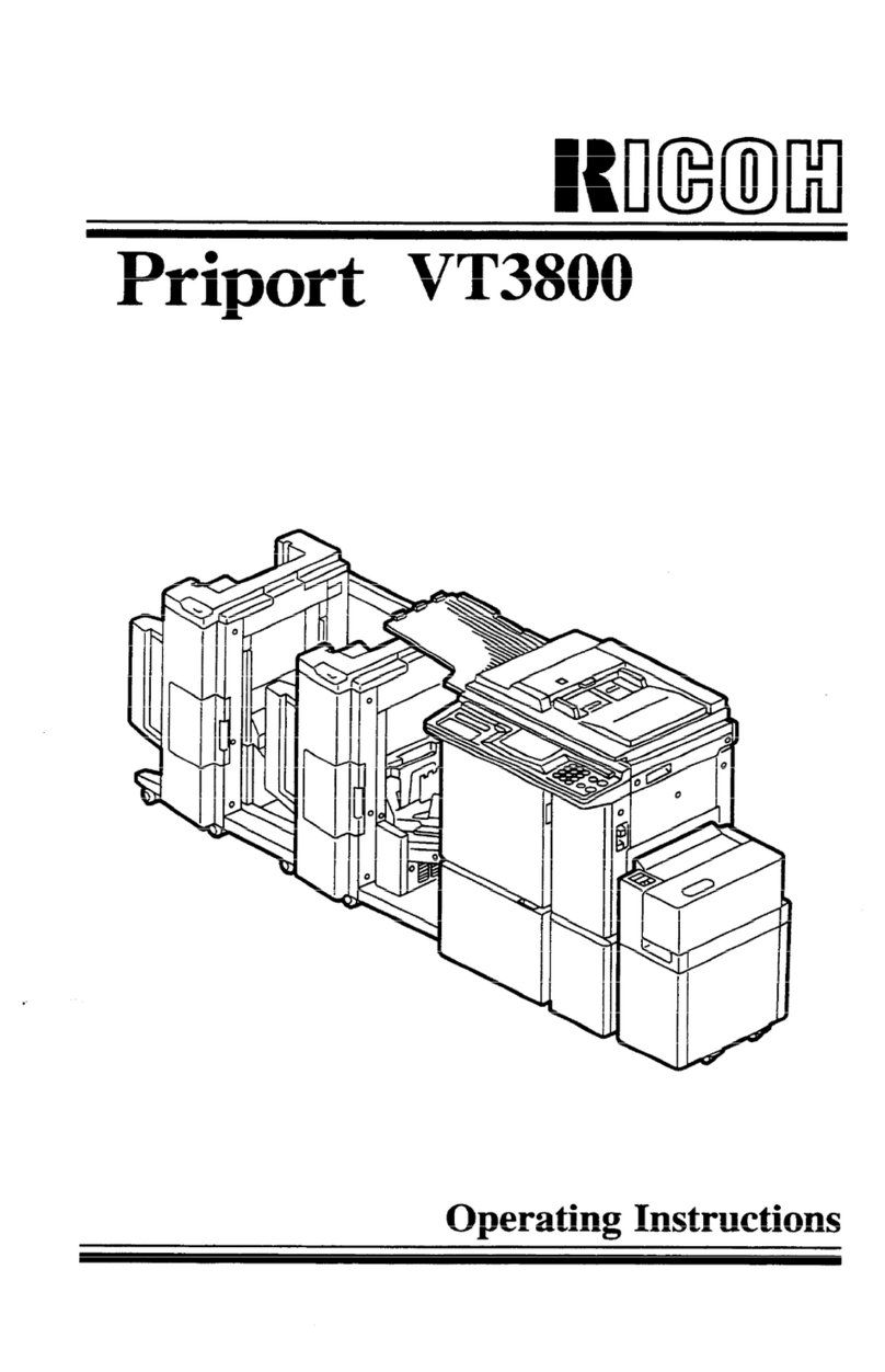
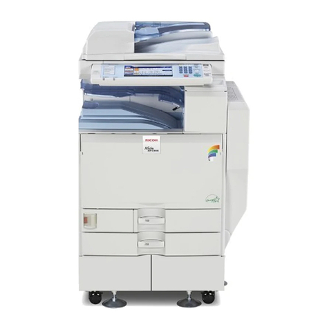
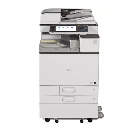
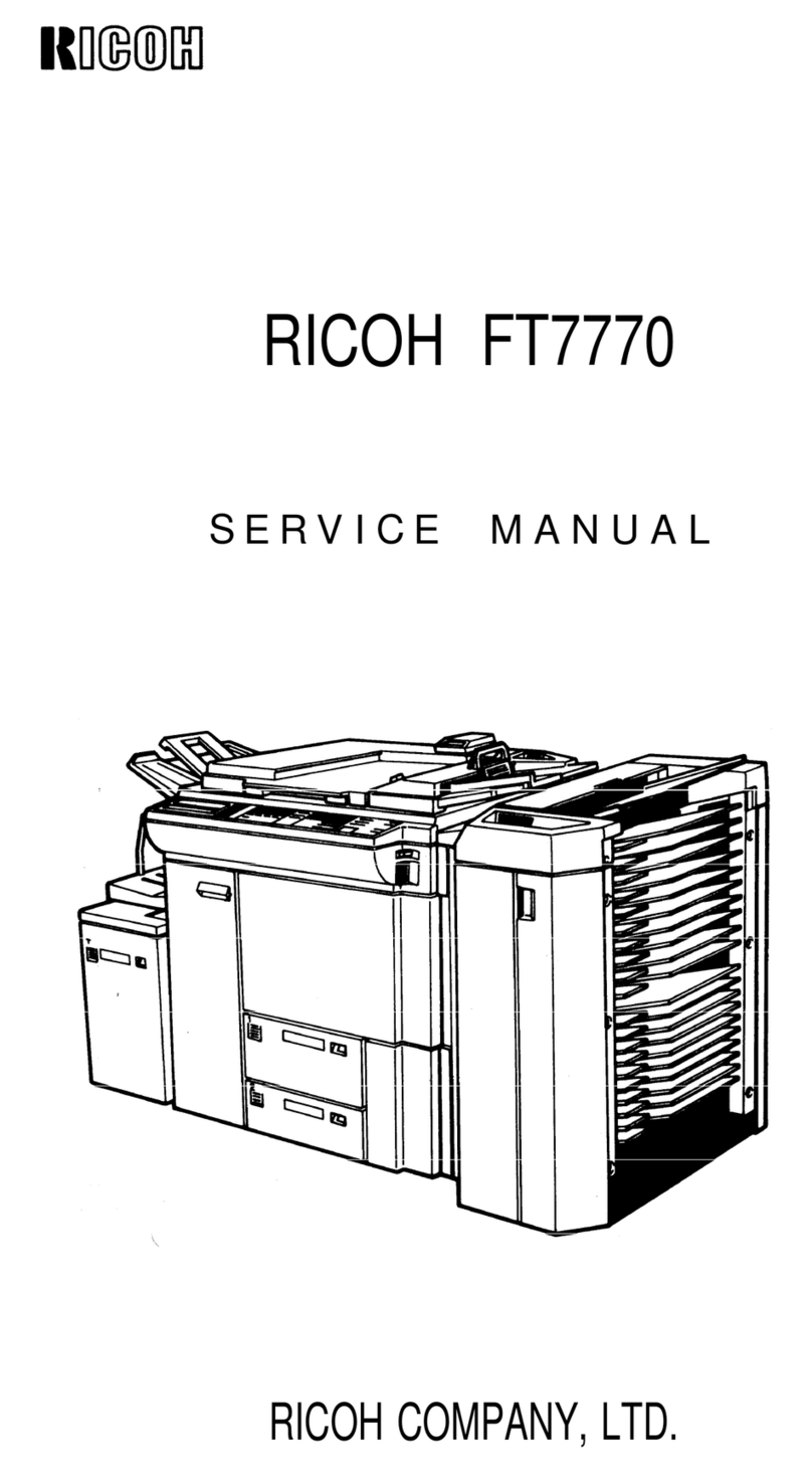
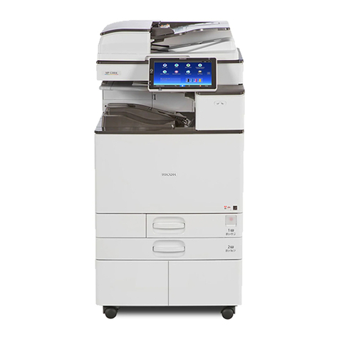
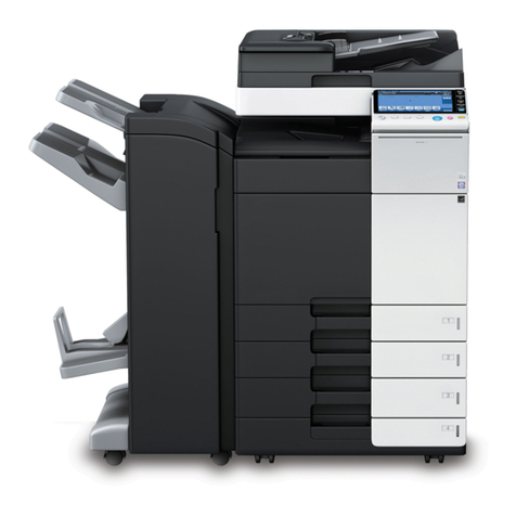
Ricoh FT8680 User manual

IMPORTANT SAFETY NOTICES
PREVENTION OF PHYSICAL INJURY
1. While the machine warms up, it will suddenly start turning to perform the
process control data initialization. Keep hands away from any mechanical
and electrical components during this period.
2. Before disassembling or assembling parts of the copier and peripherals,
make sure that the copier and the second sorter power cord is unplugged.
3. The wall outlet should be near the copier and easily accessible.
4. Note that some components of the copier, the paper tray unit, and the
2nd sorter are supplied with electrical voltage even if the main switch is
turned off.
5. If any adjustment or operation check has to be made with exterior covers
off or open while the main switch is turned on, keep hands away from
electrified or mechanically driven components.
6. The inside and the metal parts of the fusing unit become extremely hot
while the copier is operating. Be careful to avoid touching those
components with your bare hands.
HEALTH SAFETY CONDITIONS
1. Never operate the copier without the ozone filters installed.
2. Always replace the ozone filters with the specified ones at the specified
intervals.
3. Toner and developer are non-toxic, but if you get either of them in your
eyes by accident, it may cause temporary eye discomfort. Try to remove
with eye drops or flush with water as first aid. If unsuccessful, get medical
attention.

OBSERVANCE OF ELECTRICAL SAFETY STANDARDS
1. The copier and its peripherals must be installed and maintained by a
customer service representative who has completed the training course
on those models.
2. The RAM board on the main control board has a lithium battery which can
explode if replaced incorrectly. Replace the battery only with an identical
one. The manufacturer recommends replacing the entire RAM board. Do
not recharge or burn this battery. Used batteries must be handled in
accordance with local regulations.
SAFETY AND ECOLOGICAL NOTES FOR DISPOSAL
1. Do not incinerate the toner cartridge or the used toner. Toner dust may
ignite suddenly when exposed to open flame.
2. Dispose of used toner, developer, and photoconductors according to local
regulations.
3. Dispose of replaced parts in accordance with local regulations.
4. When keeping used lithium batteries in order to dispose of them later, do
not put more than 100 batteries per sealed box. Storing larger numbers or
not sealing them apart may lead to chemical reactions and heat build-up.

SECTION 1
OVERALL MACHINE
INFORMATION

1. SPECIFICATIONS
Main Copier
Copier
Configuration: Console
Copy Process: Dry Electrostatic Transfer System
Originals: Sheet/Book
Original Size: Maximum:
11" x 17", A3
420 x 700 mm (in moving-original scan mode,
Europe version only)
Copy Paper Size: Maximum:
1st and 2nd tray 11" x 17", A3
3rd tray 81/2" x 14", B4
By-pass table in moving-original scan mode
(Europe version only) 420 x 700 mm
Minimum:
Tray 51/2" x 81/2", A5
By-pass table in moving-original scan mode
(Europe version only) A5
Copy Paper Weight: Standard Copying: 14 ~ 42 lb, 52 ~ 157 g/m2
Duplex Copying: 17 ~ 28 lb, 64 ~ 105 g/m2
Tab Sheets: 90 lb index, 160 g/m2
Warm Up Time: Within 8.0 minutes (room temp. 68°F, 20°C)
First Copy Time: 3.8 seconds (81/2" x 11", A4, copier only)
6.9 seconds (81/2" x 11", A4, with sorter stapler)
Copying Speed: 80 copies/minute (81/2" x 11")
82 copies/ minute (A4)
Optional Equipment: 20 Bin Sorter 1 (A591)
20 Bin Sorter 2 (A591)
Large Capacity Tray (A592)
Key Counter Bracket Set (A598 - 00)
Key Counter (Procured locally)
Key Counter Holder (Procured locally)
Receiving Tray (spare part)
Guidance ROM Kit (A603)
31 July 1995 SPECIFICATIONS
1-1

Reproduction Ratios: See the following table:
LT/DLT version A4/A3 version
Enlargement
200% 200%
155% 141%
129% 122%
121% 115%
Full Size 100% 100%
Reduction
93% 93%
77% 82%
74% 71%
65% 65%
50% 50%
Zoom: 50 ~ 200%
Copy Exit Tray Capacity: 250 Sheets
Toner Replenishment: Cartridge exchange (1500 g)
Paper Feed: 1st tray (500 sheets)
2nd tray (500 sheets)
3rd tray (1,700 Sheets)
By-pass tray (40 sheets) (European version)
Power Source: 240 V, 20 A or more (LT/DLT version)
220, 230, 240 V, 13 A or more (A4/A3 version)
Power Consumption:
LT/DLT version
Copier only Full system*
Warm up less than 2.10 kW less than 2.15 kW
Stand-by less than 0.50 kW less than 0.55 kW
Copying less than 2.50 kW less than 2.60 kW
Maximum less than 2.60 kW less than 2.70 kW
* Full system: Copier with document feeder, large capacity tray, and a sorter stapler.
A4/A3 version (at 230 V)
Copier only Full system*
Warm up less than 2.0 kW less than 2.05 kW
Stand-by less than 0.55 kW less than 0.6 kW
Copying less than 2.4 kW less than 2.5 kW
Maximum less than 2.5 kW less than 2.6 kW
* Full system: Copier with document feeder, large capacity tray, and a sorter stapler.
SPECIFICATIONS 31 July 1995
1-2

Dimensions:
LT/DLT version
Width Depth Height
Copier with document feeder and copy tray 1,375 mm
54.2" 760 mm
30.0" 1,445 mm
56.9"
Copier with document feeder and one sorter
stapler 1,625 mm
64.0" 873 mm
34.4" 1,445 mm
56.9"
Copier with document feeder, large capacity
tray, and one sorter stapler 2,070 mm
81.5" 873 mm
34.4" 1,445 mm
56.9’
Copier with document feeder, large capacity
tray, and two sorter staplers 2,610 mm
102.8" 873 mm
34.4" 1,445 mm
56.9’
A4/A3 version
Width Depth Height
Copier with document feeder and copy tray 1,438 mm
56.7" 760 mm
30.0" 1,445 mm
56.9"
Copier with document feeder and one sorter
stapler 1,688 mm
66.5" 873 mm
34.4" 1,445 mm
56.9"
Copier with document feeder, large capacity
tray, and one sorter stapler 2,070 mm
81.5" 873 mm
34.4" 1,445 mm
56.9"
Copier with document feeder, large capacity
tray, and two sorter staplers 2,610 mm
102.8" 873 mm
34.4" 1,445 mm
56.9"
Weight:
LT\DLT version A4\A3 version
Copier with document feeder 367 kg
809.1 lb 377 kg
831.2 lb
Copier with document feeder and one sorter
stapler 465 kg
1025.2 lb 475 kg
1047.2 lb
Copier with document feeder, large capacity
tray, and one sorter stapler 506 kg
1115.6 lb 516 kg
1137.6 lb
Copier with document feeder, large capacity
tray, and two sorter staplers 596 kg
1314. 0 lb 616 kg
1358.1 lb
31 July 1995 SPECIFICATIONS
1-3

Noise Emission:
Sound pressure level
(The measurements are made according to ISO 7779 at the operator position.)
Copier only Full system*
Stand-by less than 42 dB (A) less than 42 dB (A)
Copying less than 63 dB (A)
(average) less than 64 dB (A)
(average)
* Full system: Copier with document feeder, large capacity tray, and a sorter stapler.
Sound power level (The measurements are made according to ISO 7779.)
Copier only Full system*
Stand-by less than 58 dB (A) less than 62 dB (A)
Copying less than 74 dB (A) less than 78 dB (A)
* Full system: Copier with document feeder, large capacity tray, and a sorter stapler.
Document Feeder
Original Size:
Stack feed
mode Single feed
mode Duplex mode Moving-Original
Scan
Maximum 11" x 17", A3 11" x 17", A3 11" x 17", A3 A2
Minimum 81/2" x 11", A4 51/2" x 81/2", A5 81/2" x 11", A4 B5
Original Weight:
Stack feed
mode Single feed
mode Duplex mode Moving-Original
Scan
Maximum 34 lb, 128 g/m242 lb, 157 g/m225 lb, 93 g/m293
Minimum 14 lb, 52 g/m211 lb, 35 g/m214 lb, 52 g/m252
Feed-in Unit Capacity: 50 Sheets (80 g/m2, 20 lb)
CFF Original Stack Height:Maximum: 50 mm
Original Set: First sheet on top, stack face down
SPECIFICATIONS 31 July 1995
1-4

MEMO:
31 July 1995 SPECIFICATIONS
1-5

2. COPY PROCESSES AROUND THE DRUM
1
2
3
4
5
6
78
10
9
A171V513.img
COPY PROCESSES AROUND THE DRUM 31 July 1995
1-6

1. DRUM CHARGE
In the dark, the charge corona unit gives a uniform positive charge to the selenium drum.
The charge remains on the surface of the drum because the photo conductive selenium
has electrical resistance in the dark.
2. EXPOSURE
An image of the original is reflected to the selenium drum surface via the optics assembly.
The charge on the drum surface is dissipated in direct proportion to the intensity of the
reflected light, thus producing an electrical latent image on the drum surface.
3. ERASE
The erase lamp illuminates the areas of the charged drum surface that will not be used
for the copy image. The resistance of the drum in the illuminated areas drops and the
charge on those areas dissipates.
4. DRUM POTENTIAL SENSOR
The drum potential sensor detects the electric lines of force from the electric potential on
the drum to compensate image processing elements.
5. DEVELOPMENT
Negatively charged toner is attracted to the positively charged areas of the drum, thus
developing the latent image. (The negative triboelectric charge is caused by friction
between the carrier and toner particles.)
6. PRE-TRANSFER
The pre-transfer corona (PTC) applies a negative dc charge and an ac charge to the
drum. The dc charge increases the negative potential of the toner to improve toner
transfer to paper. The ac charge decreases positive charge on the drum and makes
paper separation easier. The pre-transfer lamp (PTL) also makes paper separation easier
by illuminating the drum and decreasing the positive charge on the drum.
7. IMAGE TRANSFER
Paper is fed to the drum surface at the proper time so as to align the copy paper and the
developed image on the drum surface. Then, a strong positive charge is applied to the
back side of the copy paper, providing an electrical force which causes the copy paper to
be attracted to the drum’s surface. At the same time, the toner particles are pulled to the
copy paper from the drum’s surface.
8. PAPER SEPARATION
A strong ac corona discharge is applied to the back side of the copy paper, reducing the
positive charge on the copy paper and breaking the electrical attraction between the
paper and the drum. Then, the stiffness of the copy paper causes it to separate from the
drum surface. The pick-off pawls help to separate paper which has low stiffness.
9. CLEANING
The cleaning brush first removes remaining toner on the drum surface. Then, the cleaning
blade which is angled against drum rotation (counter blade system) removes the rest of
the toner. The flick roller mechanically removes the toner on the cleaning brush.
10. QUENCHING
Light from the quenching lamp electrically neutralizes the drum surface.
31 July 1995 COPY PROCESSES AROUND THE DRUM
1-7
3. MECHANICAL COMPONENT LAYOUT
3.1 COPIER
12
3
4
5
6
7
8
9
10
11
302928 31 32
121314151617
18
19
20
21
22
23
24
25
26 27
A171V500.wmf
1. First Mirror
2. Second Mirror
3. Third Mirror
4. Inverter Guide Plates
5. Hot Roller
6. Pressure Roller
7. Duplex Tray
8. First Tray
9. Second Tray
10. Pick-up Roller
11. Separation Roller
12. Paper Feed Roller
13. Vertical Transport Unit-Right
14. Third Tray
15. Horizontal Transport Unit
16. Pick-off Pawls
17 Transfer and Separation
Corona Unit
18. Vertical Transport Unit-Left
19. Registration Rollers
20. Pre-transfer Corona Unit
21. By-pass Feed Table
(Europe version only)
22. Toner Hopper
23. Development Unit
24. Drum Thermistor and Drum
Potential Sensor
25. Erase Lamp
26. Fifth Mirror
27. Fourth Mirror
28. Sixth Mirror
29. Charge Corona Unit
30. Quenching Lamp
31. Cleaning Unit
32. Transport Unit
MECHANICAL COMPONENT LAYOUT 31 July 1995
1-8

3.2 ARDF
12 34 5 6 7 89
10
11
12131415161718 A171V509.img
1. Original Tray Extension
2. Upper Exit Rollers
3. Upper Inverter Gate
4. Lower Inverter Rollers
5. Upper Inverter Rollers
6. Switch Back Gate
7. Switch Back Tray
8. Upper Relay Roller
9. Friction Tab
10. 1st Pick-up Rollers
11. 2nd Pick-up Rollers
12. Separation Rollers
13. Lower Relay Roller
14. Pressure Rollers
15. Transport Belt
16. Lower Inverter Gate
17. Lower Exit Rollers
18. CFF Guide
31 July 1995 MECHANICAL COMPONENT LAYOUT
1-9

4. ELECTRICAL COMPONENT DESCRIPTIONS
Refer to the electrical component layout on the reverse side of the Point to
Point (Water proof paper) index numbers.
4.1 COPIER
Name Function Index. No.
Motors
1st Tray Drive Drives the bottom plate in the 1st tray. 64
2nd Tray Drive Drives the bottom plate in the 2nd tray. 65
3rd Tray Drive Drives the bottom plate in the 3rd tray. 71
Charge Wire Cleaner Drives the charge corona wire cleaner. 79
Development Drives the development unit. 50
End Fence Drive Drives the duplex end fence. 128
Fusing Cooling Fan Cools fins of the de-curling roller. 57
Fusing Exhaust Fan Removes the heat in the de-curling unit. 63
Jogger Fence Drive Drives the duplex jogger fences. 129
LCT Drive Drives the bottom plate in the LCT. 150
Lens Horizontal Drive Shifts the lens horizontal position. 55
Lens Vertical Drive Shifts the lens vertical position. 58
Main Drives the main unit components. 77
Mirror Unit Drive Positions the mirror unit. 84
Optics Cooling 1 Removes the heat from the optics unit. 82
Optics Cooling 2 Removes the heat from the optics unit. 81
Scanner Drive Drive the 1st and 2nd scanners. 56
T & S Wire Cleaner Drives the transfer and separation wire cleaner. 75
Toner Supply Rotates the toner supply roller. 78
Vacuum Fan Removes the heat and dust in the machine. 53
Clutches
LCT Drive Transmits the main copier drive to the LCT feed
section. 52
Left Vertical Transport
Unit Drive Transmits the main copier drive to the left vertical
transport unit and the 3rd trays. 74
Paper Feed - 1st Tray Drives the paper feed roller of the 1st tray. 67
Paper Feed - 2nd Tray Drives the paper feed roller of the 2nd tray. 66
Paper Feed - 3rd Tray Drives the paper feed roller of the 3rd tray. 76
Paper Feed - Duplex Drives the paper feed roller of the duplex unit. 130
Paper Feed - LCT Drives the paper feed roller of the LCT. 138
Right Vertical Transport
Unit Drive Transmits the main copier drive to the right vertical
transport unit and the 1st and 2nd trays. 68
Registration Drives the registration roller. 72
Paper Feed - By-pass Drives the paper feed roller of the by-pass feed table. 51
PCBs
DC Drive Drives dc components. 115
DC Motor Drive Drives the dc motors. 125
ELECTRICAL COMPONENT DESCRIPTIONS 31 July 1995
1-10

Name Function Index. No.
Drum Current Detection Measures the corona current. 106
Main Controls overall machine operation. 121
Motor Control Controls the dc motors. 124
Operation Unit Controls the monitor display. 127
PTL Controls the pre-transfer lamp operation. 120
Quenching Lamp Controls the quenching lamp operation. 119
Interface Interface between the main PCB and other PCBs. 114
Vacuum Motor Controls the vacuum fan motor operation. 108
Power Packs
Charge Provides power for the charge corona wire. 103
Development Bias Provides power for the development bias. 104
PTC Provides power for the pre-transfer corona wire. 107
Separation Provides power for the separation corona wire. 105
Transfer Provides power for the transfer corona wire. 126
Power Supply Unit Provides dc power to dc components. 118
Relays
Anticondensation Heater Provides power to the anticondensation heater. 112
Drum Heater 1 Provides power to the drum heater. 113
Drum Heater 2 Provides power to the drum heater. 110
Fusing SSR Provides power to the fusing lamp. 111
Relay Unit Provides ac power to ac components. 117
Sensor
Auto Response Turns on the display from the screen saver condition. 93
By-pass Table Detects when the by-pass table is opened and
indicates the display on CRT screen. 34
Drum Potential Detects the drum surface voltage. 100
Duplex Entrance Detects misfeeds. 137
End Fence Home
Position Detects when the duplex end fence is at the home
position 136
Exit Detects misfeeds. 10
Fusing Unit Detects misfeeds. 9
Image Density Measures the density of the image on the drum. 87
Jogger Home Position Detects when the duplex side plate is at the home
position. 131
Lens Horizontal Encoder Detects the lens horizontal drive motor operation. 5
Lens Horizontal Home
Position Detects when the lens is at the horizontal home
position. 4
Lens Vertical Encoder Detects the lens vertical drive motor operation. 7
Lens Vertical Home
Position Detects when the lens is at the vertical home position. 6
Lower Limit - 1st Tray Turns off the 1st tray motor when the tray reaches the
down position. 48A
Lower Limit - 2nd Tray Turns off the 2nd tray motor when the tray reaches
the down position. 48B
31 July 1995 ELECTRICAL COMPONENT DESCRIPTIONS
1-11

Name Function Index. No.
Lower Limit - 3rd Tray Turns off the 3rd tray motor when the tray reaches
the down position. 48C
Lower Limit - LCT Turns off the LCT motor when the tray reaches the
down position. 146
Mirror Unit Encoder Detects the mirror drive motor operation. 37
Mirror Unit Home
Position Detects when the mirror unit is at the home position. 3
Paper End - 1st Tray Detects the presence of paper in the 1st tray. 49A
Paper End - 2nd Tray Detects the presence of paper in the 2nd tray. 49B
Paper End - 3rd Tray Detects the presence of paper in the 3rd tray. 49C
Paper End - By-pass
Table Detects the presence of paper in the by-pass table. 32
Paper End - Duplex Detects the presence of paper in the duplex tray. 132
Paper End - LCT Detects the presence of paper in the LCT. 141
Paper Feed - 1st Tray Turn off the 1st tray paper feed clutch. 15
Paper Feed - 2nd Tray Turn off the 2nd tray paper feed clutch. 14
Paper Feed - 3rd Tray Turns off the 3rd tray paper feed clutch. 20
Paper Feed - Duplex Turns off the duplex paper feed clutch. 133
Paper Feed - LCT Turn off the LCT paper feed clutch. 153
Paper Feed - By-pass Turn off the by-pass paper feed clutch. 36
Paper Size 1 - 1st Tray Determines what paper size is in the 1st tray. 42A
Paper Size 1 - 2nd Tray Determines what paper size is in the 2nd tray. 42B
Paper Size 1 - By-pass
Feed Determines what paper size is in the by-pass feed
tray. (European version only) 30
Paper Size 1 - LCT Determines what paper size is in the LCT. 142
Paper Size 2 - 1st Tray Determines what paper size is in the 1st tray. 41A
Paper Size 2 - 2nd Tray Determines what paper size is in the 2nd tray. 41B
Paper Size 2 - By-pass
Feed Determines what paper size is in the by-pass feed
tray. (European version only) 29
Paper Size 2 - LCT Determines what paper size is in the LCT. 143
Paper Size 3 - 1st Tray Determines what paper size is in the 1st tray. 40A
Paper Size 3 - 2nd Tray Determines what paper size is in the 2nd tray. 40B
Paper Size 3 - By-pass
Feed Determines what paper size is in the by-pass feed
tray. (European version only) 28
Paper Size 3 - LCT Determines what paper size is in the LCT. 144
Paper Size 4 - 1st Tray Determines what paper size is in the 1st tray. 39A
Paper Size 4 - 2nd Tray Determines what paper size is in the 2nd tray. 39B
Paper Size 4 - By-pass
Feed Determines what paper size is in the by-pass feed
tray. (European version only) 27
Paper Size 5 - 1st Tray Determines what paper size is in the 1st tray. 46A
Paper Size 5 - 2nd Tray Determines what paper size is in the 2nd tray. 46B
Paper Size 6 - 1st Tray Determines what paper size is in the 1st tray. 45A
Paper Size 6 - 2nd Tray Determines what paper size is in the 2nd tray. 45B
Paper Size 7 - 1st Tray Determines what paper size is in the 1st tray. 44A
Paper Size 7 - 2nd Tray Determines what paper size is in the 2nd tray. 44B
Paper Size 8 - 1st Tray Determines what paper size is in the 1st tray. 43A
Paper Size 8 - 2nd Tray Determines what paper size is in the 2nd tray. 43B
ELECTRICAL COMPONENT DESCRIPTIONS 31 July 1995
1-12

Name Function Index. No.
Paper Volume - 1st Tray Detects the amount of paper in the 1st tray. 38A
Paper Volume - 2nd Tray Detects the amount of paper in the 2nd tray. 38B
Paper Volume - 3rd Tray Detects the amount of paper in the 3rd tray. 38C
Paper Volume - LCT Detects the amount of paper in the LCT. 148
Registration Sensor Detects the lead edge of paper to determine the stop
timing of a feed clutch and detects misfeeds. 22
Return Home Position Detects when the 1st scanner is at the return position. 31
Scanner Home Position Detects when the 1st scanner is at the home position. 8
Sheet Through Home
Position Detects when the 1st scanner is at the 1 sheet
through home position. (European version only) 33
Toner Cartridge Detects when a toner cartridge is in the machine. 2
Toner Coil Overload Detects the toner collection coil drive gear operation. 1
Toner Near End Detects toner near end condition. 35
Transport Detects misfeeds. 18
LCT Paper Position Detects the top sheet position in the LCT tray. 140
Upper Limit - 1st Tray Sends signal to stop lifting up the 1st tray bottom
plate. 12
Upper Limit - 2nd Tray Sends signal to stop lifting up the 2nd tray bottom
plate. 13
Upper Limit - 3rd Tray Sends signal to stop lifting up the 3rd tray bottom
plate. 19
Upper Limit - LCT Sends signal to stop lifting up the LCT bottom plate. 151
Duplex Exit Jam detector. 16
Solenoids
Cleaning Brings the cleaning blade into contact with the drum. 54
Inverter Gate Drives the inverter gate up and down. 62
Junction Gate Drives the junction gate up and down. 61
LCT Lock Locks the LCT. 139
Pick-up - 1st Tray Lifts the pick-up roller of the 1st tray. 69
Pick-up - 2nd Tray Lifts the pick-up roller of the 2nd tray. 70
Pick-up - 3rd Tray Lifts the pick-up roller of the 3rd tray. 73
Pick-up - LCT Lifts the pick-up roller of the LCT. 149
Pick-up - By-pass Lifts the pick-up roller of the by-pass feed table. 83
Pinch Roller Brings the return pinch rollers into contact with a
paper. 60
Duplex Pressure Plate Brings the pressure plate on papers in the duplex unit. 134
Positioning Lowers the positioning roller in the duplex unit. 135
Original Scale Moves the original scale to the sheet through position
(European version only). 59
By-pass Gate Moves the by-pass gate to the down position. 80
Switches
1st Tray Down Lowers the 1st tray bottom plate. 47A
2nd Tray Down Lowers the 2nd tray bottom plate. 47B
3rd Tray Down Lowers the 3rd tray bottom plate. 47C
LCT Down Lowers the LCT bottom plate. 147
31 July 1995 ELECTRICAL COMPONENT DESCRIPTIONS
1-13

Name Function Index. No.
Anticondensation Turns on the tray heaters. 23
Error Reset Resets error condition. 11
LCT Cover Turns off components when the LCT top cover is
open. 152
Left Door 1 Turns off the main motor when the left door is open. 25
Left Door 2 Turns off dc 24 volts lines when the left door is open. 24
Main Supplies power to the copier. 26
Right Door 1 Turns off dc 24 volts lines when the right door is open. 21
Right Door 2 Turns off the main motor when the right door is open. 17
Heaters
1st Tray Removes humidity from the paper in the 1st tray. 91
2nd Tray Removes humidity from the paper in the 2nd tray. 92
3rd Tray Removes humidity from the paper in the 3rd tray. 94
Anticondensation Prevents moisture from forming on the lens and
mirrors. 101
Drum Warms the drum when it gets too cool. 95
Exposure Lamp Warms the exposure lamp when it gets too cool. 86
LCT Removes humidity from the paper in the LCT. 145
Lamps
Exposure Exposes the original with high intensity light. 85
Fusing Provides heat to the hot roller and keeps the roller at
the operating temperature. 89
Pre-Transfer Removes excessive positive charge from the drum
surface to the transfer and separation process. 98
Quenching Electrically neutralizes the drum surface prior to
charging. 97
Eraser Discharges the drum outside the image area.
Provides lead/trail edge erase. 96
Thermistors
Drum Monitors the drum temperature. 99
Fusing Monitors the hot roller temperature. 88
Other Components
Total Counter Keeps a count of the number of copies made. 116
FL Stabilizer Stabilizes power to the exposure lamp. 109
Thermofuse Provides back-up overheat protection in the fusing
unit. 90
Anticondensation
Thermoswitch Turns off the anticondensation and drum heaters. 102
ELECTRICAL COMPONENT DESCRIPTIONS 31 July 1995
1-14

4.2 ARDF
Symbol Name Function Index. No.
Motors
M1 Feed-in Drives the pick-up rollers, separation rollers
and relay rollers. 2
M2 Belt Drives the transport belt. 16
M3 Inverter Drives the inverter rollers and the exit rollers. 17
M4 Job Separation Drives the job separator. 5
Circuit Boards
PCB1 DF Main Controls overall ARDF functions. 3
PCB2 Indicator Indicates the Insert Original indicator and the
Auto Feed indicator. 6
Solenoids
SOL1 Switch Back Switches the switch back gate position to
directs the original to the switch back tray or
onto the exposure glass. 15
SOL2 Inverter Gate Opens the inverter gate. 23
SOL3 Moving Original
Scan Gate Opens the moving original scan gate
(European version only). 25
SOL4 Sheet-through
Guide Moves the sheet-through guide to the sheet
through position (European version only). 27
Sensors
S1 Entrance Cover Detects if the entrance cover is open. 4
S2 Lift Detects if the transport unit is open. 14
S3 Inverter Cover Detects if the inverter cover is open. 22
S4 Pick-up Roller
H.P. Detects if the pick-up roller is in the home
position. 1
S5 Job Separation
H.P. Detects if the job separator is in the home
position. 7
S6 Job Completion Detects that last original of the first job is fed
from the original table. 8
S7 Original Detects if the original is set on the original
table. 9
S8 Registration Sets the feed-in motor, belt motor and inverter
motor off timing. Detects original misfeed. 12
S9 Inverter Jam Detects paper jams in switch back operation. 18
S10 Inverter
Registration Sets the inverter motor and the belt motor off,
reversing timing. Detects original jams. 19
S11 Inverter Entrance Sets the inverter motor and the belt motor off,
reversing timing, inverter solenoid and switch
back solenoid off timing. 20
S12 Exit Detects paper jams. 21
S13 CFF Detects if the computer form is set in the CFF
guide. Counts the holes lined up on the
computer form. 11
31 July 1995 ELECTRICAL COMPONENT DESCRIPTIONS
1-15

S14 Original Width Detects the original width. 13
S15 Timing Supplies timing pulses to the DF main board. 10
S16 Moving Original
Scan Entrance Detects when the original is set on the moving
original scan entrance (European version only). 24
Others
Oth1 CFF Guide Switch Detects whether the CFF guide is in the rear
end position or not (European version only). 26
Oth2 Sheet Feed
Clutch Drives the sheet feed rollers (European
version only). 28
ELECTRICAL COMPONENT DESCRIPTIONS 31 July 1995
1-16

5. DRIVE LAYOUT
1. Main Motor
2. Development Drive Motor
A
B
A171V510.img
A171V511.img
G
A171V506.img
E
A171V507.img
A
CD
EF
B
2
1
C
G
A171V508.img
F
D
A : Development Unit
B : Cleaning Unit
C : Relay Transport Unit
(to LCT & By-pass Table)
D : Fusing Unit
E : Vertical Transport Unit-Right
F : Duplex Unit
G: Vertical Transport Unit-Left
A171V512.img
31 July 1995 DRIVE LAYOUT
1-17
This manual suits for next models
7
Table of contents
Other Ricoh Copier manuals

Ricoh
Ricoh FT5034 User manual

Ricoh
Ricoh Aficio MP C2051 User manual

Ricoh
Ricoh A251 User manual

Ricoh
Ricoh ST23 User manual

Ricoh
Ricoh Grand Kingfisher FT4018 User manual

Ricoh
Ricoh FT2012+ User manual

Ricoh
Ricoh Aficio DSm616 User manual

Ricoh
Ricoh 5490 User manual

Ricoh
Ricoh Aficio MP 171 Quick start guide

Ricoh
Ricoh MP C401 User manual

Ricoh
Ricoh RN-MF2 Quick start guide

Ricoh
Ricoh B286 User manual

Ricoh
Ricoh Aficio 1075 User manual

Ricoh
Ricoh 3245e User manual

Ricoh
Ricoh IS 2060 User manual

Ricoh
Ricoh Aficio FT4027 User manual

Ricoh
Ricoh PS430 User manual

Ricoh
Ricoh FW 810 User manual

Ricoh
Ricoh Aficio MP 1350 User manual

Ricoh
Ricoh aficio 1013 User manual