28 August, 2000 SPECIFICATIONS
1-1
Overall
Information
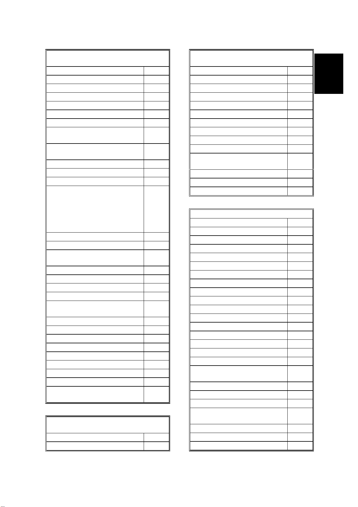
1. OVERALL MACHINE INFORMATION
1.1 SPECIFICATIONS
Type
Desktop type transceiver
Circuit
PSTN, PABX, ISDN (optional)
Connection
Direct couple
Original Size (Book)
Maximum Length: 432 mm [17 ins]
Maximum Width: 297 mm [11.7 ins]
Original Size (ADF)
Maximum: A3, 11” x 17”
Minimum: B5, 51/2” x 81/2”
Scanning Method
Flat bed, with CCD
Scan Width
210 mm [8.64 ins] ±1% (A4)
216 mm [8.5 ins] ±1% (8.5" x 11")
256 mm [10.2 ins] ±1% (B4)
279 mm [11.0 ins] ±1% (11" x 17"r)
296 mm [12.2 ins] ±1% (A3)
Resolutions
8 x 3.85 lines/mm (G3 only)
8 x 7.7 lines/mm (G3 only)
8 x 15.4 lines/mm (G3 only)
16 x 15.4 lines/mm (G3 only)
200 x 100 dpi
200 x 200 dpi
400 x 400 dpi
Note:
To use the 8 x 15.4 lines/mm, 16 x 15.4
lines/mm and 400 x 400 dpi resolutions, an
optional PMU (page memory) is required.
Memory Capacity
ECM: 128 Kbytes
SAF:
Standard: 2 Mbytes (160 pages)
With optional memory board (EXSAF):
6 Mbytes (480 pages)
With optional HDD:
80 Mbytes (3000 pages)
Measured using an ITU-T #1 test document
(Slerexe letter)
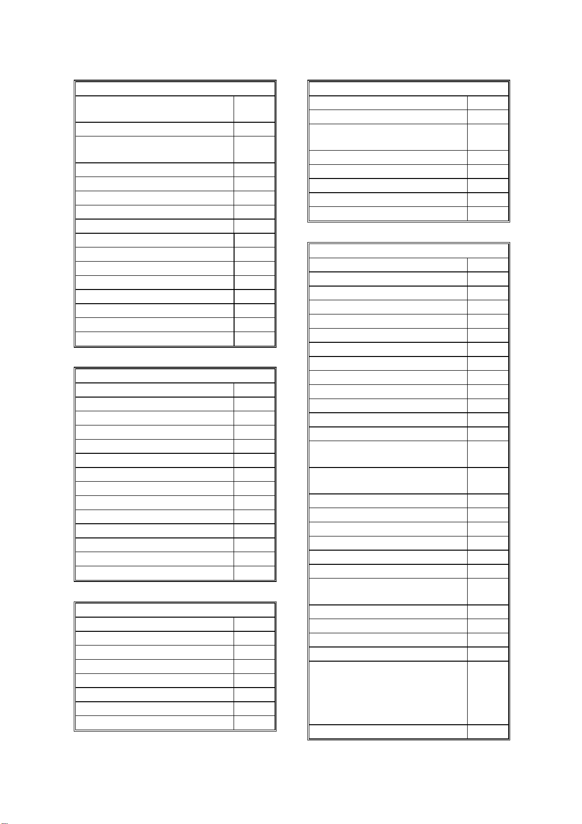
Compression
MH, MR, MMR, SSC
JBIG (PMU is required)
(MMR only with ECM and G4)
SAF storage for memory tx: MMR and raw
data
Protocol
Group 3 with ECM
Group 4 (ISDN unit required)
Modulation
V.34, V.17 (TCM), V.29 (QAM),
V.27ter (PHM), V.21 (FM)
Data Rate (bps)
G3:
33600/31200/28800/26400/24000/21600/
19200/16800/14400/12000/9600/7200/4800
/2400, Automatic fallback
G4 (option): 64 kbps/56 kbps
I/O Rate
With ECM: 0 ms/line
Without ECM: 2.5, 5, 10, 20, or 40 ms/line
Transmission Time
G3: 3 s at 28800 bps; Measured with G3
ECM using memory for an ITU-T #1 test
document (Slerexe letter) at 8 x 3.85 l/mm
resolution
G4 (option): 3 s at 64 kbps; Measured with
an ITU-T #1 test document (Slerexe letter)
at 200 x 200 dpi resolution