Operation Panel...........................................................................................................................................29
Rear Cover...................................................................................................................................................30
Upper Cover................................................................................................................................................30
By-pass Tray.................................................................................................................................................30
Left Cover......................................................................................................................................................32
Front Door.....................................................................................................................................................32
Right Cover ..................................................................................................................................................33
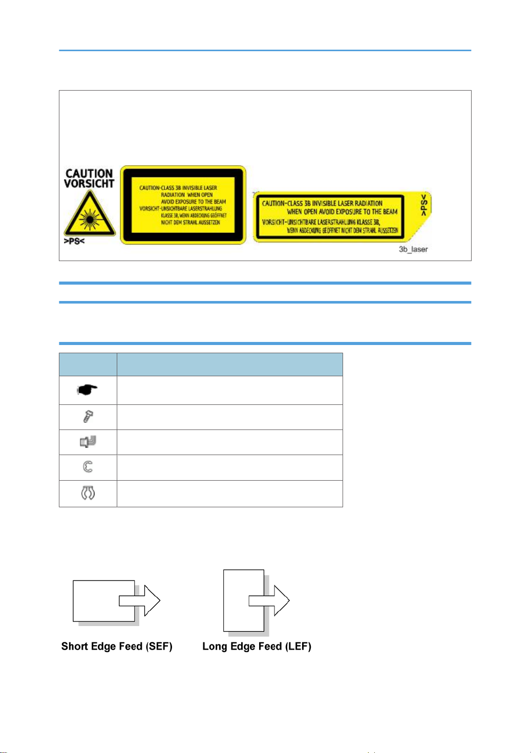
Laser Unit..........................................................................................................................................................35
Caution Decal Location ..............................................................................................................................35
Polygon Mirror Motor ................................................................................................................................36
Laser Unit......................................................................................................................................................36
Laser Diode Unit ..........................................................................................................................................38
Laser Beam Pitch Adjustment ......................................................................................................................39
Image Transfer..................................................................................................................................................41
Transfer Roller .............................................................................................................................................41
Toner End Sensor.........................................................................................................................................41
Fusing................................................................................................................................................................43
Fusing Unit....................................................................................................................................................43
Hot Roller and Fusing Lamp........................................................................................................................43
Pressure Roller..............................................................................................................................................47
Thermistor and Thermostat..........................................................................................................................49
Hot Roller Strippers......................................................................................................................................51
Paper Feed........................................................................................................................................................53
Paper Feed Roller .......................................................................................................................................53
Friction Pad ..................................................................................................................................................53
Paper End Sensor.........................................................................................................................................54
Remaining Paper Sensors............................................................................................................................55
By-pass Feed ...................................................................................................................................................56
By-pass Feed Unit........................................................................................................................................56
By-pass Feed Roller.....................................................................................................................................56
By-pass Friction Pad....................................................................................................................................57
By-pass Paper Set Sensor...........................................................................................................................59
Paper Exit .........................................................................................................................................................61
6