3
The purpose of safety symbols is to attract your attention to
possible dangers. The safety symbols and the explanations
with them deserve your careful attention and understanding.
The symbol warnings DO NOT, by themselves, eliminate
any danger. The instructions and warnings they give are no
substitutes for proper accident prevention measures.
Safety Symbols
SAFETY ALERT SYMBOL:
Indicates DANGER, WARNING, OR CAUTION; may be
used in conjunction with other symbols or pictographs.
DANGER:
Failure to obey this safety warning WILL result in death
or serious injury to yourself or to others. Always follow
the safety precautions to reduce the risk of fire, electric
shock, and personal injury.
WARNING:
Failure to obey this safety warning CAN result in
death or serious injury to you or to others. Always
follow the safety precautions to reduce the risk of
fire, electric shock, and personal injury.
CAUTION:
Failure to obey this safety warning MAY result in per-
sonal injury to yourself or to others or property damage.
Always follow the safety precautions to reduce the risk
of fire, electric shock, and personal injury.
Damage Prevention and Information
Messages
These inform the user of important information and/or in-
structions that could lead to equipment or other property
damage if they are not followed. Each message is preceded
by the word “NOTE,” as in the example below:
NOTE: Equipment and/or property damage may result if
these instructions are not followed.
WARNING:
Be sure to read and understand all safety instructions
in this manual and the manual for your power tool, in-
cluding all safety alert symbols, such as “DANGER,”
“WARNING,” and “CAUTION,” before using this Digital
Miter gauge. Failure to follow all instructions listed be-
low and in the instructions for your power tool may re-
sult in electric shock, fire, and/or serious personal
injury.
WARNING:
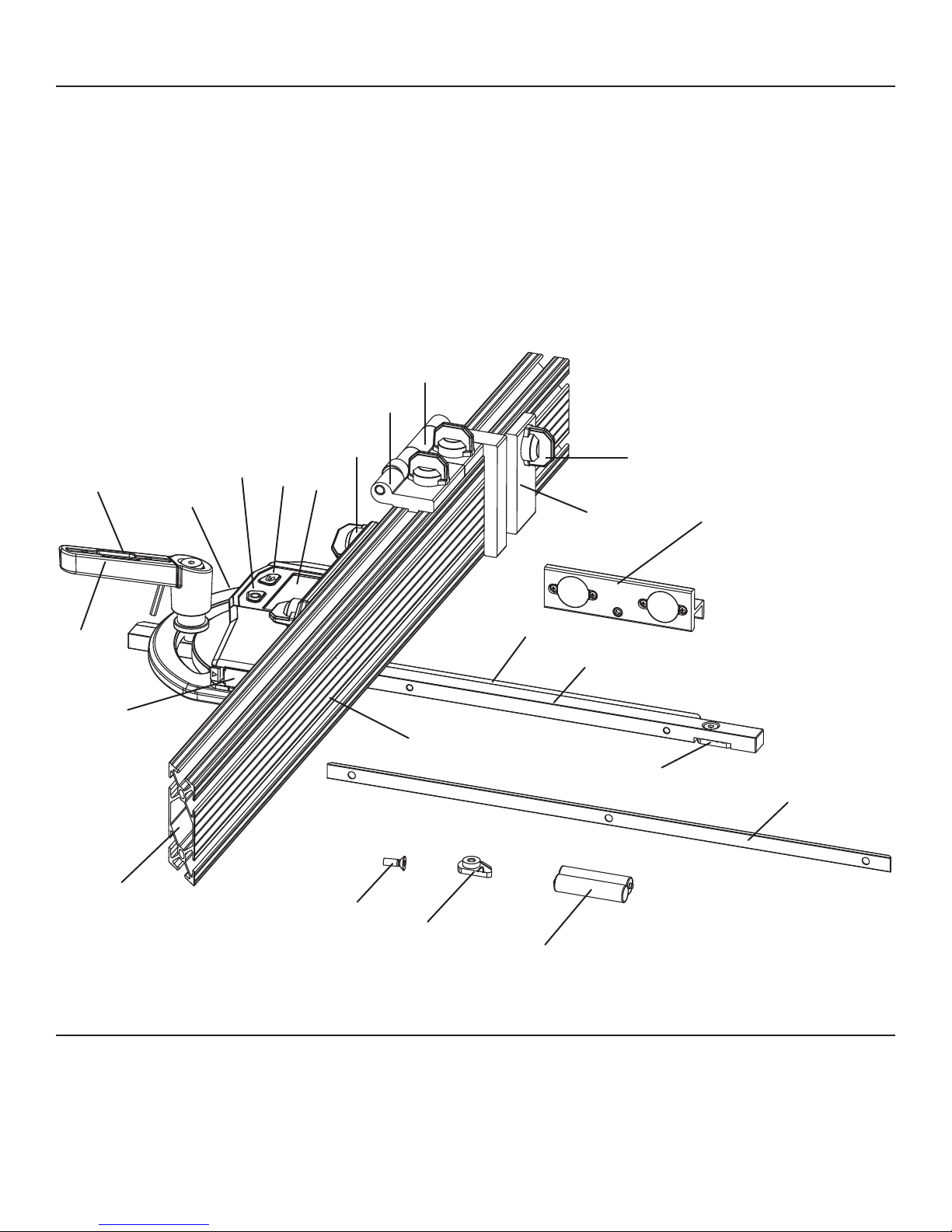
Always keep the miter fence away from the blade
when guiding the workpiece with this digital miter
gauge. Serious personal injury may result if the
metal fence comes in contact with the blade.
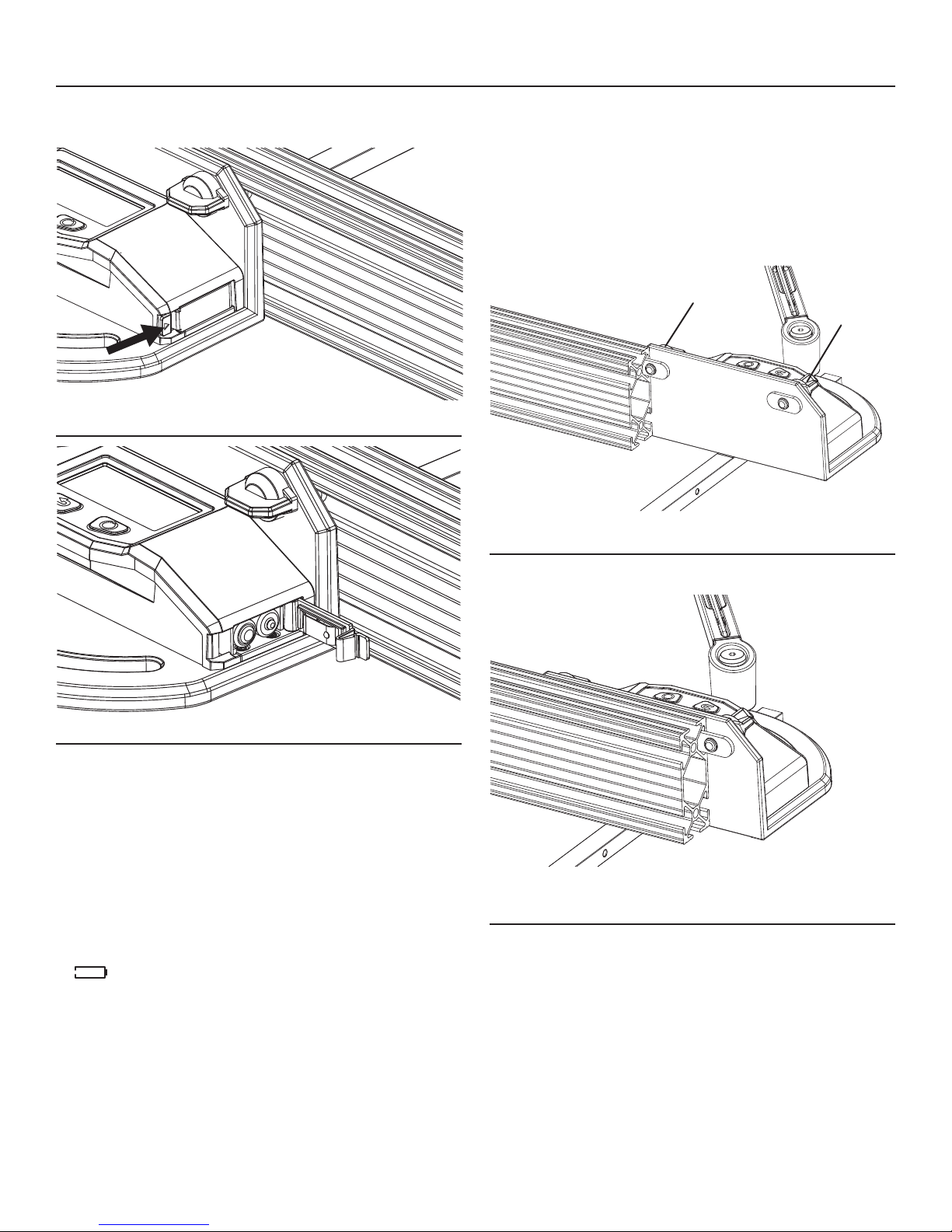
WARINING:
Before setting blade-tilt angle, make sure that the table
saw switch is in the OFF position and the plug is not
connected to a power source. Serious personal injury
may result if the saw is started by accident.
Safety Precautions for operations
•Do not use this tool for any purpose other than those out-
lined in this manual. This could result in serious injury.
•Keep the tool dry, and do not use it in the rain.
•Avoid dropping the tool and other causes of impact on the
tool.
•Remove the batteries if the device will not be used for
several days.
•Always dispose of the used batteries according to your
local ordinance; do not incinerate the batteries.
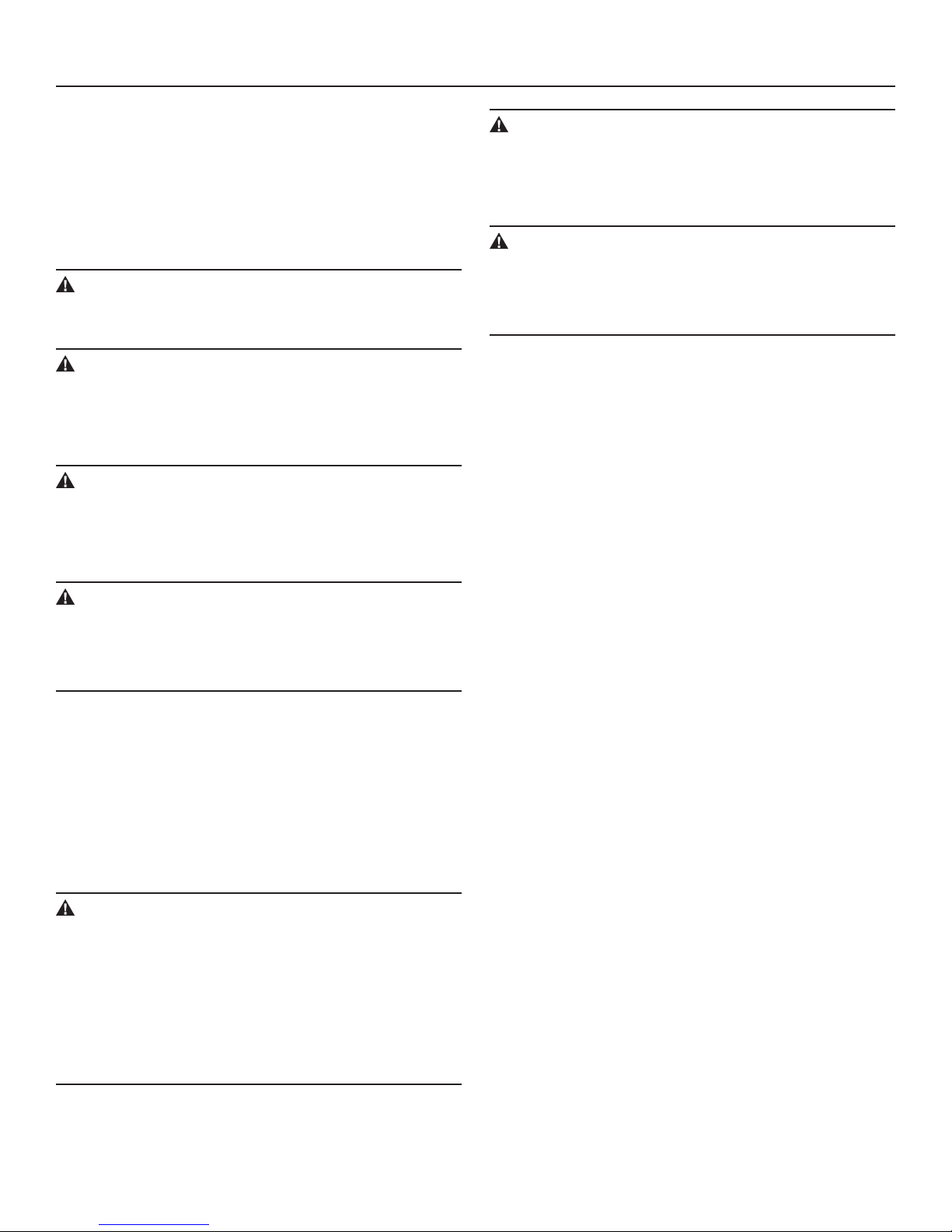
•Thedigitalmitergauge must be calibrated before using it
to set up cuts or set the saw blade angle.
Service Safety
Do not attempt to repair or disassemble the Digital Miter
Gauge. If unqualied persons attempt to repair this product,
serious injury may occur. Any repair required should be per-
formed only by authorized service personnel.
GENERAL SAFETY INSTRUCTIONS