4Besoin d’assistance? Appelez le 800-620-2790
RF-TVMP40 Support de montage mural pour téléviseur
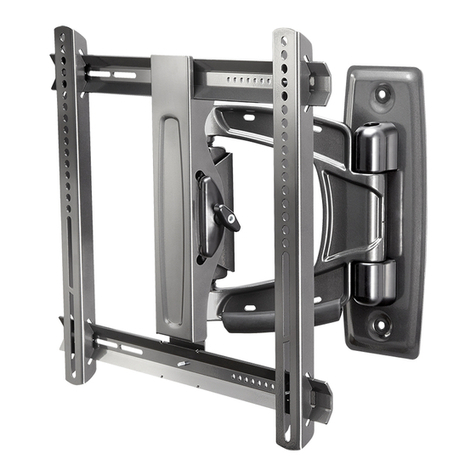
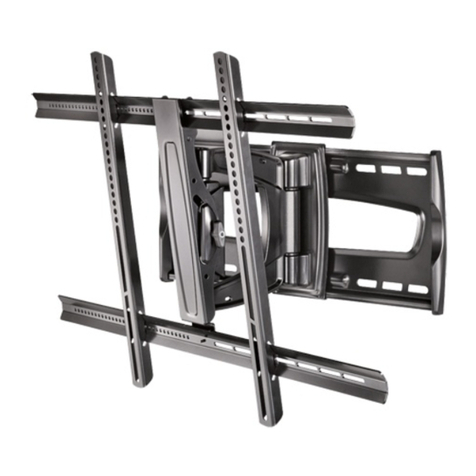
Contenu de l’emballage : éléments
Vérifier d’avoir toutes les pièces nécessaires pour assembler ce support mural neuf pour téléviseur :
Centerlineon Wood Stud or ConcreteWall
<FR>Centerlineon Wood Stud or
ConcreteWall
<SP>Centerlineon Wood Stud or
ConcreteWall
Centerof TV Mount Plate
<FR>Centerof TV Mount
Plate
<SP>Centerof TV Mount
Plate
Centerof TV Mount Plate
<FR>Centerof TV Mount
Plate
<SP>Centerof TV Mount
Plate
Centerof TV Mount Plate
<FR>Centerof TV Mount
Plate
<SP>Centerof TV Mount
Plate
Centerof TV Mount Plate
<FR>Centerof TV Mount
Plate
<SP>Centerof TV Mount
Plate
Centerof TV Mount Plate
<FR>Centerof TV Mount
Plate
<SP>Centerof TV Mount
Plate
Centerof TV Mount Plate
<FR>Centerof TV Mount
Plate
<SP>Centerof TV Mount
Plate
WallMount Bracket
<FR>WallMount
Bracket
<SP>WallMount
Bracket
Mounting Holes
<FR>Mounting
Holes
<SP>
Mounting Holes
Arm(Center,left)
<FR>Arm(Center,left)
<SP>Arm(Center,left)
Arm(Up,lef t)
<FR>Arm(Up,lef t)
<SP>Arm(Up,lef t)
Arm(Up,right)
<FR>Arm(Up, right)
<SP>Arm(Up, right)
Arm(Down, left)
<FR>Arm (Down, left)
<SP>Arm(Down, left)
Arm(Down, right)
<FR>Arm (Down, right)
<SP>Arm(Down, right)
Arm(Center,right)
<FR>Arm(Center,right)
<SP>Arm(Center,right)
side
<FR>side
<SP>side
18.19"(462mm) + Thickness of TV
<FR>18.19"(462mm) + Thickness of TV
<SP>18.19"(462mm) + Thickness of TV
24.5"(622mm) + Thickness of TV
<FR>24.5"(622mm) + Thickness of TV
<SP>24.5"(622mm) + Thickness of TV
Distancefrom the Wall
<FR>Distancefrom the Wall
<SP>Distancefrom the Wall
10"(256 mm)
<FR>10"(256 mm)
<SP>10"(256 mm)
10"(256 mm)
<FR>10"(256 mm)
<SP>10"(256 mm)
13"(323 mm)
<FR>13"(323 mm)
<SP>13"(323 mm)
13"(323 mm)
<FR>13"(323 mm)
<SP>13"(323 mm)
17"(429 mm)
<FR>17"(429 mm)
<SP>17"(429 mm)
17"(429 mm)
<FR>17"(429 mm)
<SP>17"(429 mm)
Distancebetween mounting holes and center of TV when in horizontal position and pushed in against the wall.
<FR>Distancebetween mounting holes and center of TV when in horizontal position and pushed in against the wall.
<SP>Distancebetween mounting holes and center of TV when in horizontal position and pushed in against the wall.
LEFTTV ARC
“CENTEROF TV”can be placed at any
pointalong this arc line when the arm is
pushedin against the wall and mounted
atthe centerline of your wood stud or
concretewall.
<FR>LEFTTV ARC
“CENTEROF TV”can be placed at any
pointalong this arc line when the arm is
pushedin against the wall and mounted
atthe centerline of your wood stud or
concretewall.
<SP>LEFTTV ARC
“CENTEROF TV”can be placed at any
pointalong this arc line when the arm is
pushedin against the wall and mounted
atthe centerline of your wood stud or
concretewall.
RIGHTTV ARC
”CENTEROF TV”can be placed at any
pointalong this arc line when the Arm
ispushed in against the wall and
mountedat the centerline of your
WoodStud or ConcreteWall.
<FR>RIGHTTV ARC
”CENTEROF TV”can be placed at any
pointalong this arc line when the Arm
ispushed in against the wall and
mountedat the centerline of your
WoodStud or ConcreteWall.
<SP>RIGHTTV ARC
”CENTEROF TV”can be placed at any
pointalong this arc line when the Arm
ispushed in against the wall and
mountedat the centerline of your
WoodStud or ConcreteWall.
7.68"(195 mm)
<FR>7.68"(195 mm)
<SP>7.68"(195 mm)
VerticalSpace Requirements 20" (508 mm) + Height of TV*
<FR>VerticalSpace Requirements 20" (508 mm) + Height of TV*
<SP>VerticalSpace Requirements 20" (508 mm) + Height of TV*
V113-0239
Top
Dessus
Partesuperior
RF-TVMP40Template • Gabarit • Plantilla
Note
Remarque: Pour une construction à ossature de bois, localiser
d'abordles montants en bois, à l'aide d'un détecteur de montants.
Nota:para la instalación en construcciones de armazón de madera,
primerodebe localizar las vigas de madera con un localizador de vigas.
ToolsNeeded
Outilsnécessaires
Herramientasrequeridas
Top
Dessus
Partesuperior
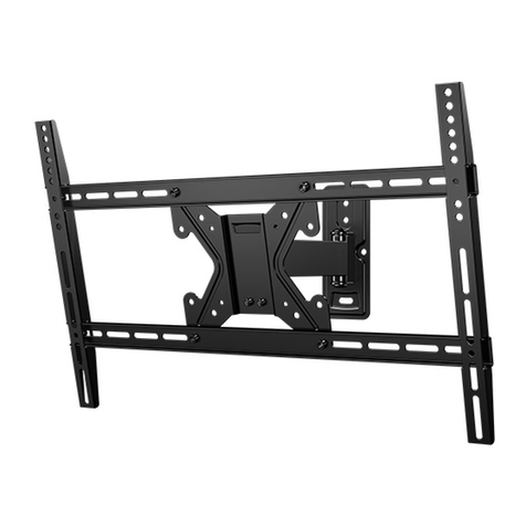
ABras de montage (1) DPlaque murale (1)
ECouvercles de la plaque murale (2)
BCouvercle du bras arrière (1)
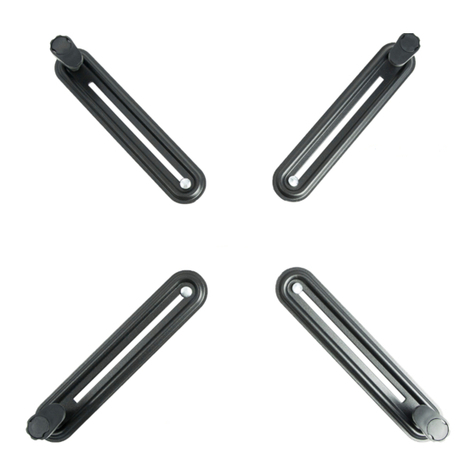
FAdaptateurs en étoile (4)
CPlaque de moniteur VESA (1)
GGabarit
RF-TVMP40_13-0389_MAN_V2_FR.fm Page 4 Friday, April 19, 2013 11:16 AM


