Estas y otras instrucciones de productos ROTOR están disponibles en:
www.rotorbike.com
Pol. Ind. Conmar. C/Miño, 14. 28864 AJALVIR MADRID SPAIN Tel. +34 918843846 Fax. +34 918843865
AVISOS DE SEGURIDAD
El manual de usuario contiene información muy útil e importante acerca de la correcta instalación, uso y
mantenimiento de su producto ROTOR. Debe leer, comprender y seguir cuidadosamente las instrucciones
que aparecen en dicho manual. Mantenga el manual en un lugar seguro para futuras consultas.
No realice ninguna modificación o ajuste que no esté explícitamente descrita en el manual. Si tuviera
alguna duda sobre su capacidad para llevar a cabo la instalación o mantenimiento, por favor, acuda a un
taller cualificado.
Una instalación u operación de mantenimiento incorrecta puede reducir drásticamente el rendimiento del
producto y podría provocar un accidente con resultado de lesiones o incluso la muerte.
Por favor, lleve su bicicleta regularmente a un taller cualificado para inspeccionar cualquier signo de fatiga,
rotura, deformación o exceso de uso. Cualquier componente que se encuentre en mal estado por exceso
de uso, fatiga, rotura, deformación o impactos ha de ser reemplazado inmediatamente.
No llevar a cabo un mantenimiento adecuado reduce drásticamente la vida útil del producto así como su
rendimiento.
Si tiene cualquier duda, comuníquela en su punto de venta ROTOR más cercano o contacte con
MANTENIMIENTO
Inspeccione sus componentes ROTOR en busca de impactos, fisuras, pérdida de piezas o deformaciones
antes de cada uso, así como después de cada caída. Si hay presencia de algunas de las circunstancias
previamente mencionadas, no use sus componentes hasta que no hayan sido sustituidos.
ATENCIÓN: El uso continuado de piezas dañadas, puede ocasionar pérdida de control de la bicicleta, así
como daños severos e incluso la muerte.
Es responsabilidad del usuario examinar el producto regularmente para determinar su revisión o
sustitución. El ciclista debe inspeccionar la bicicleta, así como sus componentes, con frecuencia para
localizar daños producidos por el uso normal o abusivo. Revise, por favor, estos daños después de cada
salida.
Controle también periódicamente el apriete correcto de la tornillería, pero no sobreapriete los tornillos.
CONDICIONES DE GARANTÍA
- Los productos ROTOR y todos sus componentes están garantizados durante 2 años contra cualquier fallo de fabricación o material
defectuoso. En el caso de existir alguna avería durante el período de garantía, ROTOR Componentes Tecnológicos se compromete a
reparar o sustituir el componente o producto defectuoso sin cargo para el cliente. Además, en algunos países, ROTOR está obligado a
asegurar cualquier garantía legal, definida por la ley de cada país, para la protección del usuario.
- Los componentes con una vida útil limitada por el uso y las roturas no achacables a defectos de fabricación no están cubiertas por esta
garantía.
- Fallos o roturas causadas por un uso inapropiado, instalación defectuosa o un mantenimiento inadecuado (según se indica en el
manual de usuario) no están cubiertos por esta garantía.
- Conserve su factura de compra, pues le permitirá ejercer su derecho como comprador a la garantía.
- La garantía será anulada en los siguientes casos:
- Incumplimiento de los requisitos anteriormente mencionados.
- Instalación inadecuada.
- Uso negligente o instalación de piezas inadecuadas.
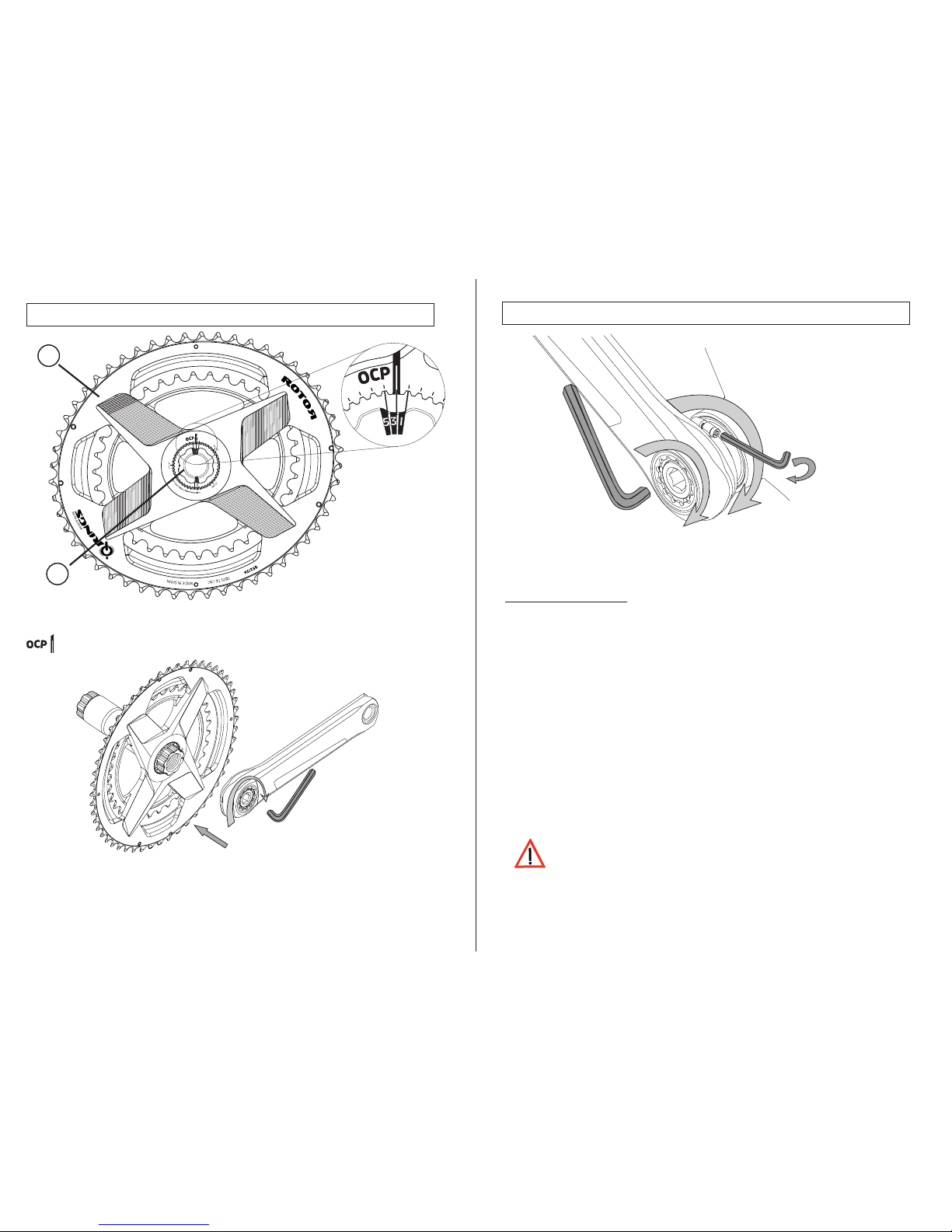
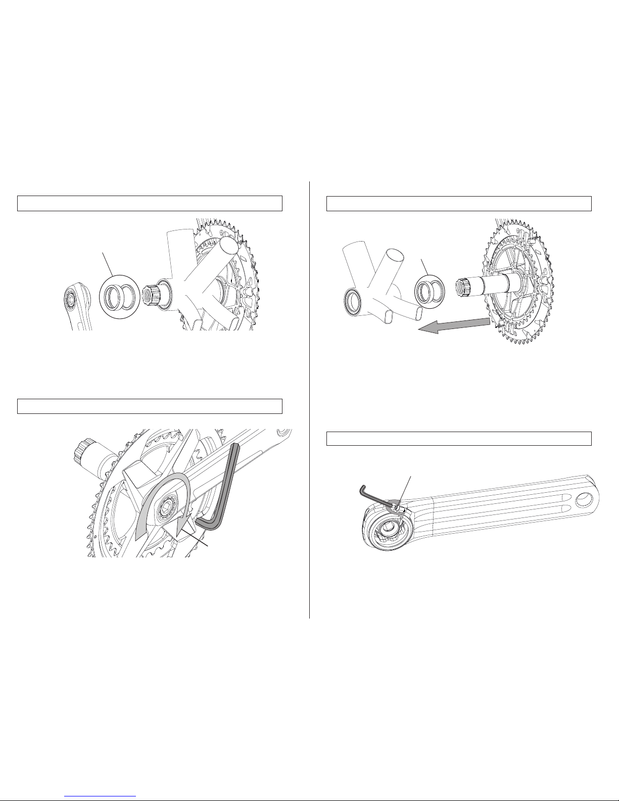
ALDHU 3D+ - OCP MOUNT
INSTALLATION GUIDE
ROTOR COMPONENTES TECNOLÓGICOS SL
C/Miño, 14. Pol.Ind. Conmar. 28864, Ajalvir, Madrid, Spain.
Phone: +34 91 884 38 46 / Fax: +34 91 884 38 65
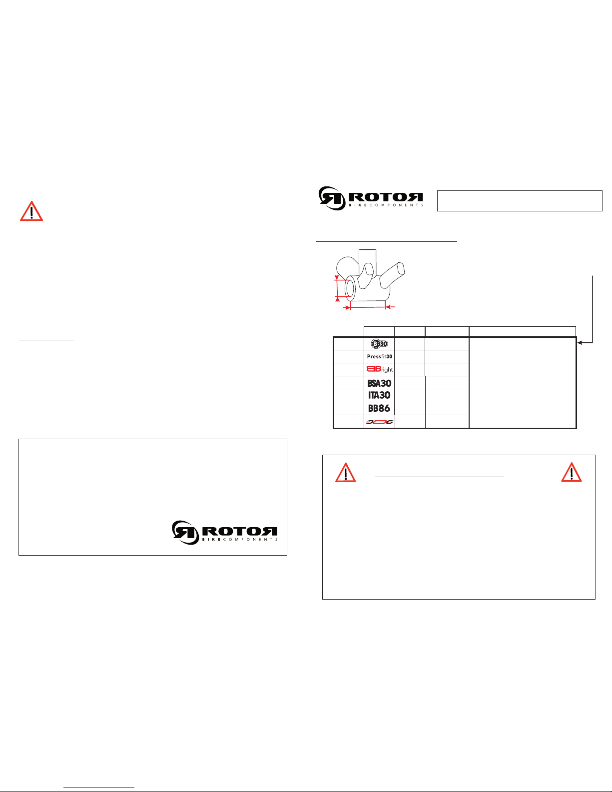
ALDHU 3D+ FRAME COMPATIBILITY:
Note: instructions are subject to change without notice.
Review: 08/2017
Bottom bracket not included with cranks package.
ADVICE BEFORE INSTALLATION:
Read all instructions included in the manual before installing any
component.
Uninstall or modify the product other than as stated in the information
contained in this manual.
Please obey the rules and regulations of the country, state or region; for
further information contact your local distributor.
Verify that all the components are installed with the recommended torque,
as shown in this manual.
This manual is only valid for the following road
frames: BB30, PressFit30, BBright y BBright Ca.
1
2
3
68mm
68mm
70mm
42mm
46mm
ITA
thread
5
86.5mm 41mm
7
79mm 42mm (BBright Ca)/
46mm (PressFit)
6
86mm 46mm
68mm BSA
thread
4
Follow this user manual
instructions.
Review the compatibility manual
to select necessary spacers
before installing the cranks.
WD
MANUAL COMPATIBILITY
FRAME
P95-002-00102-002
W
D