manuals.online logo
Brands
  1. Home
  2. •
  3. Brands
  4. •
  5. roundhouse
  6. •
  7. Toy
  8. •
  9. roundhouse HBK18 Katie R/C Fittings Only Kit User manual

roundhouse HBK18 Katie R/C Fittings Only Kit User manual

1
Modular Locomotive System
HBK18 Katie R/C Fittings
Only Kit
Instruction Manual
Roundhouse Engineering Co. Ltd.
Units 6-9 Churchill Business Park. Churchill Road,
Wheatley. Doncaster. DN1 2TF. England.
Tel. 01302 328035
Fax. 01302 761312
Email. support@roundhouse-eng.com
Note:- this kit contains the parts to enable radio control
equipment to be fitted to a ‘Katie’ locomotive. No radio control
equipment is included with this kit.
www.roundhouse-eng.com
ONLINE
2
HBK18 Katie R/C Fittings Kit
Introduction
These instructions cover the fitting of radio control to the
HBK15/16/17 ‘Katie’ 0-4-0 locomotive kit.
It contains all necessary brackets, fixings etc. to enable the
builder to fit his or her own radio equipment.
Roundhouse ‘Katie’ locomotives are fitted as standard with
2.4 GHz two-channel radio control equipment and all fixings
and brackets are designed for this. If using different
equipment, ensure that it is of similar specification or
problems could be encountered.
2.4 GHz radio control equipment should be used as this gives
fine control with the minimum of interference.
Before starting assembly, check contents against the list and
read through the instructions fully, referring to diagrams where
necessary, so that you identify all parts and understand where
each is fitted.
You will need to supply
A 2.4 GHz two-channel radio control set complete with
transmitter, receiver, switch harness and two micro
servos’ (Hitec HS81 or equivalent).
Standard or mini servos will not fit correctly. If three or four
channel equipment is used, only two channels are needed for
this locomotive.
3
Construction
Folding battery box and chassis cover plate.
First of all, fold up the etched brass battery box and chassis
cover plate as shown above and paint them as required. Note
that all half etched fold lines should be to the inside of the fold.
All painting is left to the builder and Acrylic paint is readily
available in spray cans for a good finish. A good primer is
essential and, if available, an etch primer should be used on
brass parts. A good model shop will stock more specialised
paints and should include etch primer in the range. Read
carefully and follow the maker’s instructions that appear on
the can before using any paint. All parts must be thoroughly
cleaned and rubbed down with fine wet and dry paper prior to
painting.
4
The locomotive body should first be removed to allow
installation of the radio control equipment.
Reversing Servo
1 - Reversing servo-mounting posts. 2 - Reversing servo.
3 - Short servo horn. 4 - Reversing control rod.
5 - Quicklink connector.
Fit the reversing servo that operates the Walschaerts valve-
gear first.
The servo mounts on to the left hand side of the footplate with
the three coloured lead to the rear, using the two brass posts.
Fit the brass servo posts to the servo first using two M3 brass
screws and two brass washers. Fit the servo and posts to the
cab floor using two M3 brass screws) as shown above.
The lead should be fastened to the bottom of the rear servo
5
mounting post with a plastic cable tie, and then passed down
through the small rectangular hole to the left of the boiler.
Do not fit the horn or linkage at this time.
Regulator Servo
1 - Regulator arm.
2 - Push rod connector.
3 - Regulator control rod with Quicklink and lock nut.
4 - Regulator servo.
Fit the regulator servo to the bracket on the right hand side of
6
the foot plate (which you fitted during the body construction).
The servo is passed through the rectangular hole in the
bracket from the rear with the lead to the top. The lead can
then be passed down the front of the servo between it and the
gas tank and through the rectangular hole in the footplate to
the left of the servo. Fasten the servo in place with a M3 x 6
brass screw, washer and nut through the top and bottom
mounting flange.
Do not fit the horn or linkage at this time.
Fit the switch to the rear of the
right hand frame, in the cut out
in the frame. The switch body
sits on the inside of the frame
with the slider pointing out.
One of the switch leads (see
your r/c equipment instruction book for details) will plug into
the receiver, do not alter this. The other lead will go to the
battery holder and this must be modified to connect to the new
battery holder supplied with this kit.
Switch harnesses from different manufacturers vary in length
and the type of plug and socket used to connect their normal
battery holder. It is often easier just to cut the plug from the
end of this lead and attach the PP9 lead, but check lengths
before doing so. The lead must be extended by soldering the
PP9 type clip to its end to give an overall length of about 6½"
from the floor. Before soldering the wires together, pass the
lead up through the left hand footplate cut-out (where the
reversing servo lead passes through). Slide the battery lead
through the large diameter heat shrink tubing, but do not
shrink the tubing yet.
Ensure that both red wires and both black wires are
7
connected together. Two short lengths of the small diameter
shrink-wrap about ½" (13mm) long should be cut from the
2” (5 cm) piece supplied, to insulate the soldered joints.
Shrink-wrap is a special rubber tube, which reduces in
diameter when heated. To use it, first slide it over the end of
one of the two wires to be joined then, after the wires are
soldered together, slide it back to cover the exposed joint and
overlap the insulation at little at each side.
Finally, rub the hot soldering iron over the shrink-wrap and it
will close tightly round the joint.
In order to set and adjust the linkages, the r/c equipment must
be connected up and batteries fitted.
The short lead from the switch should be plugged into the
receiver in the socket typically marked (B) or BATT. The other
lead with the PP9 clip then attaches to the battery holder. For
now, just lay the battery holder at the side of the loco; it will be
fitted to the body later.
The receiver will be housed between the frames under the
footplate area and retained by the chassis cover plate
supplied with this kit.
8
Chassis Cover Plate
Plug the regulator servo lead into channel 2 on the receiver
and the reversing servo lead into channel 1.
All loose wires, except the long battery wire can be tidied up
using the cable ties supplied. Ensure that none are in contact
with hot pipes or fittings and out of the way of any moving
parts. Finally, fit the chassis cover plate to protect the switch
and receiver. The two small tags which are bent upwards go
either side of the chassis and will line up with two tapped
holes in the frames for two M3 x 6 brass retaining screws. The
9
large flap fits up between the frames behind the rear wheels.
When in place this cover boxes in the rear portion of the
chassis - see picture on opposite page.
Now that the main items are installed, we can fit and adjust
the linkages, first however, the spring which self-centres the
left hand (regulator) control arm on the transmitter needs
removing. The right hand control (reverser) can be left
sprung loaded to centre as this gives a convenient mid-gear
position. Refer to the manufacturer’s instructions regarding
the removal of this spring as details vary on different makes
of radio control equipment.
Fit four AA batteries in the receiver battery clip then connect
the battery clip to the end of the battery lead from the switch.
Switch on both transmitter and receiver.
Moving the right hand control lever should now cause the
reversing servo to operate and moving the left hand lever
should cause the regulator servo to operate. If this is not the
case, check all connections and batteries.
Set the reversing servo up first as follows.
Prepare a servo horn so that it has a single arm with a
connection hole approximately 8mm from the centre. If none
of the arms supplied with your r/c set have a suitably
positioned hole, you will have to drill one using a 1/16" or
1.6mm drill. The positioning of this hole is quite critical as it
will affect the travel of the radius rod in the expansion link,
but as different makes and types of servo have slightly
different angles of movement, it is not possible to give an
exact measurement - some trial and error is required.
10
Reversing Servo Push Rod Connection
1- Starlock washer.
2- Pushrod connector.
3- Lock screw
Fit a push rod connector as shown in diagram 5. Push the
spigot through the hole from the front and push the Starlock
washer over the spigot to lock it on. Fit the screw in the end of
the connector loosely.
Trim the plastic servo arm to length.
Ensure that the control lever on the transmitter is in the centre
and that the trimmer (small black lever below the main lever)
is also in the centre then push the short servo arm up onto the
splined servo spindle pointing in towards the boiler at 90
degrees and fix in place with its retaining screw.
The shaped cut-out in the footplate below the servo will allow
screwdriver access to the horn and push rod connector
11
screws.
This has now set the servo horn for mid gear and moving the
control lever either way will move the horn accordingly.
Set up the transmitter, using the servo reversing switch if
necessary, so that moving the lever to the left engages
forward gear (moves horn forwards) and to the right engages
reverse (moves servo horn to the rear).
Using the reversing control rod already fitted or the longer of
the two rods provided, slide the straight end through the cross
hole in the push rod connector.
Connect the Quicklink connector into the hole in the lifting arm
by springing open the end of the Quicklink and passing the pin
through the hole in the top of the lifting arm.
Now, check for movement to full gear in both directions and
make fine adjustments to the linkage by moving the rod in the
push rod connector until the radius rod moves an equal
amount both up and down the expansion slot.
Note that the radius rod should not travel the full length of the
expansion link, but should stop a small distance from either
end.
On some transmitters there is an extra refinement to aid us in
this setting in the form of three extra ‘trimmers’. The left hand
one labelled ‘Throttle Quick Trim’ can be ignored, as this now
has no function. The other two, labelled ‘CHI ATV CH2’
control the amount of rotation of the two servo spindles and
‘CH 1’ can therefore be used to adjust the maximum raising
and lifting of the radius rod.
12
A replacement r/c type regulator is supplied with this kit.
Although externally it looks the same as the manual type
supplied with the boiler kit, internally it is quite different. It is
designed to operate with a servo where a small amount of
movement must give full control from closed to fully open. It
also relies on a '0' ring to ensure that it closes fully with the
minimum of force.
Although the standard needle valve supplied with the boiler
can be used with radio control, its operation, particularly in
closing fully, is not always reliable.
Fitting of the r/c type regulator to the boiler is the same as for
the manual type and is described fully in the boiler kit
instructions.
Prepare the regulator arm by first bending the regulator arm
as shown in the picture opposite. This will allow the regulator
control rod to connect the regulator servo horn to the regulator
arm, in a straight line.
Fit the push rod connector to the fourth hole with the centre
boss of the arm and the push rod connector both on the same
side. Push the spigot through the hole from the front and push
the Starlock washer over the spigot to lock it on. Fit the screw
in the end of the connector loosely. See picture opposite.
Set the left hand control lever on the transmitter to the bottom
and ensure that the trimmer at the side of it is at the top. This
will park the servo in its normally closed position.
13
Regulator Push Rod Connector
1 - Clamp screw.
2 - Push rod connector.
3 - Starlock washer.
Prepare a servo horn with a single arm and four connection
holes. Fit the horn so that it is pointing to roughly half way
between 8 and 9 on a clock face and fix it in place with the
small screw provided. When the left hand control lever is
moved upwards, the servo horn will rotate anticlockwise.
If it travels clockwise, use the servo reverse switch located on
the transmitter then reset the horn as above. Turn the
regulator spindle clockwise with your fingers to close it, but do
not force it. Fit the regulator arm to the spindle with its centre
boss and push rod connector facing the rear, placing it roughly
parallel to the servo horn and nip up the grub screw using the
same Allen key supplied for the wheel grub screws. Using the
14
supplied linkage, Quicklink and lock nut, connect the regulator
arm to the servo horn as shown in diagram 3. First pass the
plain end of the rod through the push rod connector on the
regulator arm, and then clip the Quicklink in either the 2nd or
3rd hole on the servo horn. The Quicklink is best fitted by
slightly spreading the two sides with a screwdriver as you
pass it over the servo arm.
Setting and adjustment of the regulator is best done with the
locomotive in steam and with the chassis supported on two
wooden blocks under the chassis to raise the wheels off the
bench. Ensure that the regulator is closed when raising
steam.
With full working pressure raised, switch on both transmitter
and receiver and move the locomotive into gear with the right
hand lever on the transmitter. Open the regulator by slowly
moving the left hand lever upwards and find the position at
which the engine starts to run. Move the arm backwards and
forwards a few times to establish the position at which it
closes and leave it there. If the regulator does not open or
fails to close fully, slacken the grub screw holding the
regulator arm in place, remove the arm and turn the spindle
manually (careful as it's hot!) to find the point at which it just
closes. Move the control lever on the transmitter to the bottom
and replace the regulator arm. Proceed as before to find its
closing position and leave it there. Carefully slacken the grub
screw and move the control lever to the bottom without
moving the spindle. Nip up the grub screw.
You can make fine adjustments to the linkage now until the
regulator closes fully with the control lever at the bottom.
Because of the '0' ring used in the r/c type regulator, you
should aim for the wheels to start moving when you have
moved the control lever on the transmitter about half way up.
15
This is because the '0' ring will compress slightly into its seat
when fully closed. You may need to adjust the position of the
arm on the spindle, the control rod in the push rod connector,
or position of the Quicklink on the servo horn to achieve this.
When satisfied that all is adjusted correctly, tighten all screws,
switch off the gas burner and r/c equipment and disconnect
battery clip. Trim off any excess servo horn.
The trimmer at the side of the control arm can be used in the
future to compensate for wear and compression of the '0' ring.
As time passes, you may find that the regulator does not fully
close when the control lever is at the bottom. As this happens,
the trimmer can be moved down a little at a time to
compensate.
The locomotive body can now be refitted, ensuring that the
battery lead passes up inside the front left hand corner of the
cab away from any hot or moving parts.
Using the two 8BA x 3/16” countersunk screws and nuts, fix
the etched brass battery box to the underside of the cab roof
using the holes provided. Position it so that when the cab roof
is hinged up, the writing on the battery box is the right way up.
This will ensure that the small tab at one end of the battery
box is nearest the cab front.
Ensure that all links etc. have been tightened and that all
wires are safely and securely routed.
Finally, slide the battery clip into the box under the cab roof,
with the connections at the front and clip on the PP9
connector. Check position carefully so that the cab roof closes
fully without the battery holder, clip or wires fouling anything.
This concludes the fitting and adjustment of the radio control
equipment.
16
HBK18 Checklist for Katie R/C Fittings Only Kit
1 Etched brass chassis cover plate
1 Etched brass battery box
1 Plastic battery holder (4 x AA batteries not included)
1 Battery connector clip with lead (PP9 type)
2 Reversing servo mounting posts threaded M3
8 M3 x 6 Screws plus 4 M3 Nuts Plus 4 Washers
1 Regulator control rod with Quicklink and lock nut
(approximately 7cm long including Quicklink)
1 Reversing control rod with Quicklink and lock nut
(approximately 11cm long including Quicklink)
2 Push rod connectors, screws and starlock washers
1 Steam regulator with arm and 1 grub screw (r/c type)
1 18 cm length of large diameter shrink wrap
1 3 cm length of medium diameter shrink-wrap
1 5 cm length of small diameter shrink-wrap
2 8BA x 3/16" CSK. Screws and 2 x 8BA nuts
3 Plastic cable ties.
Checked
www.roundhouse-eng.com

Other roundhouse Toy manuals

roundhouse Katie User guide

roundhouse

roundhouse Katie User guide

roundhouse Vale of Rheidol 2-6-2 User guide

roundhouse

roundhouse Vale of Rheidol 2-6-2 User guide

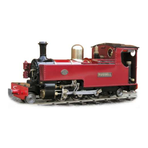
roundhouse RUSSELL User guide

roundhouse

roundhouse RUSSELL User guide

roundhouse Little John User guide

roundhouse

roundhouse Little John User guide

roundhouse Linda User guide

roundhouse

roundhouse Linda User guide

roundhouse Darjeeling C Class User guide
roundhouse

roundhouse Darjeeling C Class User guide

roundhouse FOWLER User guide

roundhouse

roundhouse FOWLER User guide

roundhouse DARJEELING 'B' CLASS User guide

roundhouse

roundhouse DARJEELING 'B' CLASS User guide

roundhouse Criccieth Castle User guide

roundhouse

roundhouse Criccieth Castle User guide

roundhouse Carrie User guide

roundhouse

roundhouse Carrie User guide

roundhouse ATLANTIC User guide

roundhouse

roundhouse ATLANTIC User guide

roundhouse HBK8 User manual

roundhouse

roundhouse HBK8 User manual

roundhouse MILLIE User guide

roundhouse

roundhouse MILLIE User guide

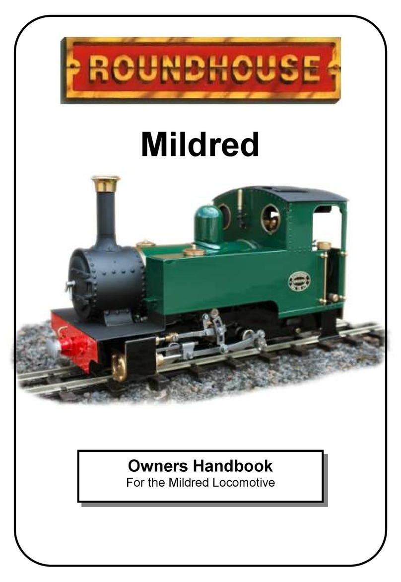
roundhouse Mildred User guide

roundhouse

roundhouse Mildred User guide

roundhouse TOM ROLT User guide

roundhouse

roundhouse TOM ROLT User guide

roundhouse WILLIAM User guide

roundhouse

roundhouse WILLIAM User guide

roundhouse SR&RL 24 User guide

roundhouse

roundhouse SR&RL 24 User guide
roundhouse Darjeeling 'D' Class Garratt User guide

roundhouse

roundhouse Darjeeling 'D' Class Garratt User guide

roundhouse TALIESIN User guide

roundhouse

roundhouse TALIESIN User guide

roundhouse Beddgelert 0-6-4 User guide

roundhouse

roundhouse Beddgelert 0-6-4 User guide

roundhouse LEEK & MANIFOLD User guide

roundhouse

roundhouse LEEK & MANIFOLD User guide

roundhouse SAMMIE & BERTIE User guide
roundhouse

roundhouse SAMMIE & BERTIE User guide

Popular Toy manuals by other brands

Extreme Flight VANQUISH MKII instruction manual

Extreme Flight

Extreme Flight VANQUISH MKII instruction manual

Hasbro Transformers Animated Bulkhead 83619/83617 instruction manual

Hasbro

Hasbro Transformers Animated Bulkhead 83619/83617 instruction manual

Mega Construx Destiny FMK05 quick start guide

Mega Construx

Mega Construx Destiny FMK05 quick start guide

Power Wheels Kawasaki KFX NINJA B9272 Owner's manual & assembly instructions

Power Wheels

Power Wheels Kawasaki KFX NINJA B9272 Owner's manual & assembly instructions

Hoomeda Life Long Love Pc2011 instruction manual

Hoomeda

Hoomeda Life Long Love Pc2011 instruction manual

MGA Entertainment Little Tikes Fantastic Firsts Spinning RC quick guide

MGA Entertainment

MGA Entertainment Little Tikes Fantastic Firsts Spinning RC quick guide

Trix H0 Kof III manual

Trix

Trix H0 Kof III manual

Agora Models Mitsubishi A6M ZERO Fighter Build instructions

Agora Models

Agora Models Mitsubishi A6M ZERO Fighter Build instructions

Faller 2 viaduct piers quick start guide

Faller

Faller 2 viaduct piers quick start guide

Eduard F-8E/J wing central section quick start guide

Eduard

Eduard F-8E/J wing central section quick start guide

The Learning Journey Techno Gears Crazy Train instruction manual

The Learning Journey

The Learning Journey Techno Gears Crazy Train instruction manual

Modellbau Laffont Z3001 Assembly instructions

Modellbau Laffont

Modellbau Laffont Z3001 Assembly instructions

Maxford USA Bleriot XI instruction manual

Maxford USA

Maxford USA Bleriot XI instruction manual

TILLIG BAHN 16571 quick start guide

TILLIG BAHN

TILLIG BAHN 16571 quick start guide

Robinson R44 Pilot operating handbook

Robinson

Robinson R44 Pilot operating handbook

Hasbro Transformers Meteorfire Cyberverse Adventures Battle Call Trooper Class... manual

Hasbro

Hasbro Transformers Meteorfire Cyberverse Adventures Battle Call Trooper Class... manual

Mattel W SLAM CITY GORILLA IN THE CELL MATCH instructions

Mattel

Mattel W SLAM CITY GORILLA IN THE CELL MATCH instructions

Kyosho EP Concept SR-K instruction manual

Kyosho

Kyosho EP Concept SR-K instruction manual

manuals.online logo
manuals.online logoBrands
  • About & Mission
  • Contact us
  • Privacy Policy
  • Terms and Conditions

Copyright 2025 Manuals.Online. All Rights Reserved.