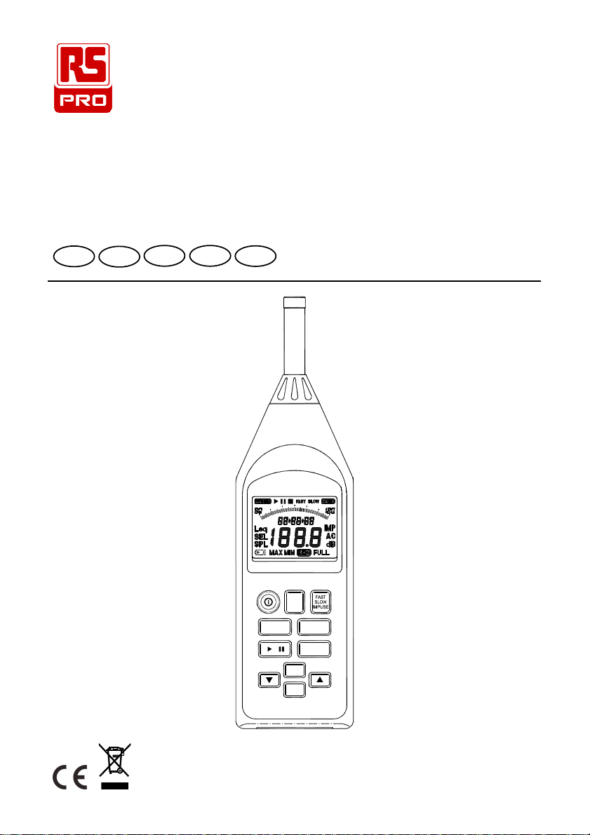
RS PRO SLM 1353M User manual

INSTRUCTION MANUAL
SLM 1353M
Integrating Sound Level Meter
FREN IT DE ES
INTEG
DATE
TIME
TIME
A/C
ERASE
Leq SEL SPL
RECORD
MAX

Integrating Sound Level Meter / EN
08/15/16 Version No. 01
CONTENTS
Title Page
1. INSTRUMENT CARE.....................................................................................1
2. FEATURES.....................................................................................................2
3. MEASUREMENT PARAMETERS..................................................................3
4. SPECIFICATIONS..........................................................................................4
5. CONTROLS AND FUNCTIONS...................................................................11
6. LCD DISPLAY DESCRIPTION.....................................................................14
7. PREPARATION FOR USE ...........................................................................16
8. CALIBRATION PROCEDURE .....................................................................18
9. MEASUREMENT PROCEDURE..................................................................19
10. SETTING THE CURRENT TIME AND DATE.............................................22
11. STORE RECORD DATA OPERATION.......................................................23
12. OUTPUT CONNECTORS...........................................................................28
13. ADJUSTMENT DATA FOR CALIBRATOR (B&K TYPE 4226 PRESSURE
MODE)........................................................................................................29
14. TYPICAL INSTRUMENT FREQUENCY RESPONSE AT 0°
INCIDENCE.30
15. TYPICAL FREQUENCY RESPONSE DUE TO CASE REFLECTIONS AT 0°
INCIDENCE................................................................................................31
16. TYPICAL FREQUENCY RESPONSE FOR INSTRUMENT FITTED WITH
WINDSCREEN AT 0°
INCIDENCE.............................................................32
17. DIRECTIONAL CHARACTERISTICS OF THE COMPLETE INSTRUMENT
....................................................................................................................33
18. APPENDIX A FREQUENCY WEIGHTING NETWORK.............................36
19. APPENDIX B RMS DETECTION CIRCUIT AND TIME WEIGHTING.......37
20. APPENDIX C INFLUENCE OF BACKGROUND NOISE...........................39

Integrating Sound Level Meter / EN
1 08/15/16 Version No. 01
1. INSTRUMENT CARE
Do not attempt to remove the mesh cover from the microphone as this will cause
damage and affect the accuracy of the instrument.
Protect the instrument from impact. Do not drop it or subject it to rough handling.
Transport it in the supplied carrying case.
Protect the instrument from water, dust, extreme temperatures, high humidity and
direct sunlight during storage and use.
Protect the instrument from air with high salt or sulphur content, gases and stored
chemicals, as this may damage the delicate microphone and sensitive electronics.
Always turn the instrument off after use. Remove the batteries from the instrument
if it is not to be used for a long time. Do not leave exhausted batteries in the
instrument, as they may leak and cause damage.
Clean the instrument only by wiping it with a soft, dry cloth or, when necessary, with
a cloth lightly moistened with water. Do not use any solvents, alcohol or cleaning
agents.

Integrating Sound Level Meter / EN
08/15/16 Version No. 01 2
2. FEATURES
The SLM 1353M Sound Level Meter complies with the requirements of
IEC 61672-1: 2003 standard for a Class 2 instrument.
The instrument contains several features which permit sound level measurements
under a variety of conditions.
Features include:
Ease of use.
Easy to read large display.
Five measurement ranges.
Fast, Slow and Impulse time weightings.
A and C frequency weightings.
Storage of up to 32000 measurement records.
USB serial port for downloading records to a computer or real time analysis to a
computer.
Both AC and DC signal outputs are available from a single standard 3.5mm
coaxial socket suitable for use with a frequency analyzer, level recorder, FFT
analyzer, graphic recorder, etc.
Leq, SEL, SPL MAX, SPLMIN, PH (Peak Hold), L05, L10, L50, L90, and L95, ten
measured parameters are monitored during measurement and can be viewed
selectively by pressing the button.
Preset measurement time up to 24 hours.
Sound level alarm output connector.

Integrating Sound Level Meter / EN
3 08/15/16 Version No. 01
3. MEASUREMENT PARAMETERS
The following parameters are used on the instrument.
A →“A” frequency weighting sound pressure level
C →“C” frequency weighting sound pressure level
FAST →Fast time weighting
SLOW →Slow time weighting
IMP →Impulse time weighting
SPL →Current time-weighted sound pressure level
Leq →Equivalent continuous sound level
SEL →Sound exposure level
SPL MAX →Maximum sound pressure level
SPL MIN →Minimum sound pressure level
PH →Peak Hold sound pressure level
L:05 →5% percentile sound level
L:10 →10% percentile sound level
L:50 →50% percentile sound level
L:90 →90% percentile sound level
L:95 →95% percentile sound level
SPL“MAX” →Maximum time-weighted sound pressure level (MAX symbol blink)
The various settings depend on the condition the instrument was in before it was last
turned off.

Integrating Sound Level Meter / EN
08/15/16 Version No. 01 4
4. SPECIFICATIONS
Specifications apply to Model SLM 1353M fitted with Microphone model MC-22 and
Microphone Preamplifier model AP-21
Applicable standards: IEC61672-1: 2003 Class 2
IEC60651: 1979 Type 2
ANSI S1.4: 1983 Type 2
IEC60804: 1985 Type 2
Measurement functions:
•
Main processing functions
Sound level: Current time-weighted sound pressure level Aor current
time-weighted sound pressure level C
Maximum time-weighted sound pressure level A or Maximum time-weighted
sound pressure level C
Equivalent continuous sound level Leq A or Leq C
Sound exposure level SEL A or SEL C
Peak Hold sound level PHA or PHC
Percentile sound level L : 05 Aor L : 05 C
L : 10 A or L : 10 C
L : 50 A or L : 50 C
L : 90 A or L : 90 C
L : 95 A or L : 95 C
•
Measurement time : 1second to 24 hours
•
Measuring ranges
RMS : Total range: 30 to 130dB
Peak Hold : A– weighted or C – weighted over the top 30dB of each
measurement range.
30 – 90 : 63 – 93dB Peak Hold
40 – 100 : 73 – 103dB Peak Hold
50 – 110 : 83 – 113dB Peak Hold
60 – 120 : 93 – 123dB Peak Hold
70 – 130 : 103 – 133dB Peak Hold
•
Max. measurement level: 130dB
•
Self-generated noise level:
Typical values at 23°C using the nominal microphone equivalent capacitance of 27pF
(30-90dB range)
Weighting Electrical Total
“A” 22.7dB 26.1dB
“C” 21.8dB 29.5dB

Integrating Sound Level Meter / EN
5 08/15/16 Version No. 01
Linearity operating range: A-weighted, 1000Hz, 60dB dynamic range.
Total linear operating range:
In accordance with IEC 61672-1,A-weighted, 1000Hz: 30dB to 130dB.
Level range selection:
5 ranges in 10dB steps 30 to 90dB , 40 to 100dB
50 to 110dB , 60 to 120dB
70 to 130dB
LINEAR OPERATING RANGES (L.O.R.)
RANGE: 30 – 90 dB. Test starting point 64 dB for all weightings and frequencies except
31.5Hz A-weighted, for which the starting point is 44 dB.
FREQUENCY
Hz WEIGHTING
L.O.R.
dB WEIGHTING L.O.R.
dB
31.5 A 36.1 – 50.6 C 39.5 – 87.0
1000 A 36.1– 90.0 C 39.5 – 90.0
4000 A 36.1 – 90.0 C 39.5 – 89.2
8000 A 36.1 – 88.9 C 39.5 – 87.0
RANGE: 40 – 100 dB. Test starting point 74 dB for all weightings and frequencies except
31.5Hz A-weighted, for which the starting point is 54 dB.
FREQUENCY
Hz WEIGHTING L.O.R.
dB WEIGHTING L.O.R
dB
31.5 A 40.0 – 60.6 C 40.0 – 97.0
1000 A 40.0 – 100.0
C 40.0 – 100.0
4000 A 40.0 – 100.0
C 40.0 – 99.2
8000 A 40.0 – 98.9 C 40.0 – 97.0
RANGE: 50 – 110 dB. Test starting point 84 dB for all weightings and frequencies except
31.5Hz A-weighted, for which the starting point is 64 dB.
FREQUENCY
Hz WEIGHTING
L.O.R
dB WEIGHTING L.O.R
dB
31.5 A 50.0 – 70.6 C 50.0 – 107.0
1000 A 50.0 – 110.0 C 50.0 – 110.0
4000 A 50.0 – 110.0 C 50.0 – 109.2
8000 A 50.0 – 108.9
C 50.0 – 107.0

Integrating Sound Level Meter / EN
08/15/16 Version No. 01 6
RANGE: 60 – 120 dB. Test starting point 94 dB for all weightings and frequencies except
31.5Hz A-weighted, for which the starting point is 74 dB.
FREQUENCY
Hz WEIGHTING
L.O.R.
dB WEIGHTING
L.O.R.
dB
31.5 A 60.0 – 80.6 C 60.0 – 117.0
1000 A 60.0 – 120.0 C 60.0 – 120.0
4000 A 60.0 – 120.0 C 60.0 – 119.2
8000 A 60.0 – 118.9 C 60.0 – 117.0
RANGE: 70 – 130 dB. Test starting point 104 dB for all weightings and frequencies
except 31.5Hz A-weighted, for which the starting point is 84 dB.
FREQUENCY
Hz WEIGHTING
L.O.R.
dB WEIGHTING L.O.R.
dB
31.5 A 70.0 – 90.6 C 70.0 – 127.0
1000 A 70.0 – 130.0
C 70.0 – 130.0
4000 A 70.0 – 130.0
C 70.0 – 129.2
8000 A 70.0 – 128.9
C 70.0 – 127.0
Frequency range:
Overall characteristics including microphone: 31.5 to 8000Hz
Frequency weighting: A,meets the requirement of IEC 61672-1 for class 2
“A” weighting.
C,meets the requirement of IEC 61672-1 for class 2
“C” weighting.
Time weighting (RMS detection): Fast, according to IEC 61672-1 class 2.
Slow, according to IEC 61672-1 class 2.
Impulse, according to IEC 61672-1 class 2.
•
Reference conditions:
Type of the acoustic field: Free
Reference sound pressure level: 94.0dB (related to 20µPa)
Reference level range: 60 to 120dB
Reference frequency: 1000Hz
Reference temperature: +23°C
Reference relative humidity: 50%RH
Reference static pressure: 101.325 kPa
Reference incidence direction: Perpendicular to the front of the microphone
diaphragm.
•
Calibration: Acoustic using calibrator SLC 1356, B&K 4231 or equivalent.
Calibration check frequency is 1000Hz.
Nominal calibration level for the free field: 94.1dB
Nominal calibration level for the diffuse field:94.0dB

Integrating Sound Level Meter / EN
7 08/15/16 Version No. 01
•
Frequency for acoustic testing: 8000Hz.
•
Warm-up time:
≦
2min
•
Sampling interval: Bar graph indication →125 ms approx.
Numeric indication →1 sec approx.
•
Data record capacity: Data can be stored in the memory.
Max. 32000 data can be stored.
Max. 255 blocks can be split.
•
Microphone equivalent electrical impedance (electrical input device) : Replace
the microphone capsule with a series capacitance of 27pF +/- 3pF
Microphone:
•
Model: MC-22
•
Nominal diameter: 1/2 inch electret condenser type
•
Sensitivity: -27dB (0dB = 1V/Pa)
•
Frequency response: 31.5Hz to 8000Hz
•
Capacitance: 27pF
•
Reference direction and position: Perpendicular to the front of the microphone
diaphragm at its geometric centre.
•
Maximum input sound level: 131dB at microphone for no damage.
•
Operating temperature: -10°C to +50°C
•
Temperature coefficient: Approx. 0.005dB/°C at 1000Hz
•
Dimensions: 13.2dia x 14mm
Frequency Response
-5.0
0.0
5.0
31.5Hz 63Hz 125Hz 250Hz 500Hz 1000Hz 2000Hz 4000Hz 8000Hz
(dB)
Freq
units
31.5
Hz 63
Hz 125
Hz 250
Hz 500
Hz 1000
Hz 2000
Hz 4000
Hz 8000
Hz
dB +0.4
+0.3
+0.2
+0.1
0.0 +0.1
+0.3
+0.8
-0.5
Typical free-field response 0°incidence

Integrating Sound Level Meter / EN
08/15/16 Version No. 01 8
-20.0
-10.0
0.0
10.0
20.0
31.5Hz 63Hz 125Hz 250Hz 500Hz 1000Hz 2000Hz 4000Hz 8000Hz
(dB)
Freq
units
31.5
Hz 63
Hz 125
Hz 250
Hz 500
Hz 1000
Hz 2000
Hz 4000
Hz 8000
Hz
dB +1.2
+0.7
+0.4
+0.2
0.0 0.0 0.0 +0.1
-3.7
Typical diffuse-field response for random incidence
Preamplifier:
•
Model: AP-21
•
Input impedance: 470MΩ
•
Output impedance: 550Ωat 1000Hz
•
Maximum input voltage: 2.828V peak-to-peak at electrical input for no damage.
•
Measuring input (viewed from top of instrument):
A: ground
B: ground
C: +10V
D: signal input
E: N.C.
Display LCD
•
Display screens:
4 digit numerical indication of sound level, from 30.0 to 130.0dB with 0.1dB
resolution.
Bar-graph indication of current sound level with 1dB resolution.
Sound level range indicator: 30–90dB, 40–100dB, 50–110dB, 60–120dB or
70–130dB in five ranges.
Time display; year – month – day and hour: minute: second.
•
Display update rate: 1 second
•
Display first indication: Depends on the condition the instrument when it was last
turned off.

Integrating Sound Level Meter / EN
9 08/15/16 Version No. 01
•
Warning indications:
Out-of-range indications:
OVER displayed at upper limit of the range
UNDER displayed at lower limit of the range
Outputs
•
AC output (using selected frequency weighting)
Output voltage: 2Vrms (at full-scale of the range)
Output impedance: 5kΩ
Load impedance:
≧
1MΩ
•
DC output
Output voltage: 10mV/dB
Output impedance: 5kΩ
Load impedance:
≧
1MΩ
•
I/O connector: Sound level meter control from and data output to a computer (USB)
•
Alarm output: 5Vdc, typical
Clock: Real–time (with calendar)
Power requirements
•
Qty 4 x 1.5V IEC R6P (size “AA”) manganese super heavy duty batteries or
equivalent.
•
Battery life: Approx. 24 hours
•
Internal back-up battery: Maintains real-time clock operation for at least 6 months
(typically) if fully charged.
•
External power source: DC voltage from 5V to 6V
Current rating: Approx. 20mA @ 6V
Ambient conditions:
•
Operating conditions: -10°C to +50°C, 30% to 90%RH non-condensing
•
Storage conditions: -10°C to +60°C, <70%RH non-condensing
•
Effect of temperature: < 0.5dB (-10 to +50°C)
•
Effect of humidity: < 0.5dB (for 30%RH to 90%RH at 40°C, 1000Hz)
•
Effect of vibration: A 40 Hz 1m/s vibration produces no noticeable effect.
•
Effect of magnetic field: No noticeable effect.

Integrating Sound Level Meter / EN
08/15/16 Version No. 01 10
Compliance with standards:
•
:indicates compliance with applicable European Union Directives.
•
EMC Emission: IEC 61000-6-3, Generic emission standard for residential,
commercial and light industrial environments.
No significant emissions from the instrument.
IEC 61672-1, Instrumentation standard classification group X and
performance class 2 sound level meter.
•
EMC Immunity: IEC 61000-6-2, Generic standard-Immunity for industrial
environments.
No degradation in performance when subjected to 10V/m for 80%
modulation at 1kHz.
IEC 61672-1, Instrumentation standard classification group X and
performance class 2 sound level meter.
No permanent degradation of performance, loss of function,
change of operating state or configuration, or loss or corruption of
stored data due to ESD discharges as specified in the above
standard.
•
No degradation in performance when the instrument was subjected to ESD at 8kV
per IEC 801-2.
Dimensions: Approx. 265x72x36mm
Weight (including battery): Approx. 380g
Supplied accessories: Instruction manual, Batteries, Adjustment screwdriver, PC
software, Windscreen, USB connecting cable, 3.5φplug,
Carrying case.
Optional equipment (Not supplied): AC adaptor, Sound calibrator SLC 1356.

Integrating Sound Level Meter / EN
11 08/15/16 Version No. 01
5. CONTROLS AND FUNCTIONS
1. Microphone and preamplifier: The MC-22 microphone capsule is connected to the
AP-21 preamplifier for normal operation. The
microphone capsule may be carefully removed from
the preamplifier and substituted with the appropriate
electrical impedance (See sect. 4. “Specifications”)
for electrical verification of the instrument.
2. Display: The LCD shows the sound level as a numeric value and a bar graph. The
display also shows the operation mode of the instrument, the selected
measurement parameters, warning indications and real-time
clock/calendar.
3. Button: Press to turn the instrument on and off.

Integrating Sound Level Meter / EN
08/15/16 Version No. 01 12
4. button : Press this button the following parameters are monitored during
integrating measurement and can be viewed selectively :
Leq with integrating start time.
SEL with integrating stop time.
SPL MAX Maximum sound level with time.
SPL MIN Minimum sound level with time.
PH Peak Hold sound level.
L05, L10, L50, L90, and L95 percentile sound levels.
5. button :
Press to start ( “ ” measurement symbol) or pause ( “ ” pause symbol) the
integrating sound level measurement (including the various processing functions)
or the data recording. When the measurement period is completed, the ( “” end
symbol) indication is shown on the display.
Press this button 2 seconds to exit the integrating measurement or the data record.
If the end “” symbol is shown on the display, press this button 2 seconds will clear
the last integrating measure data and the “” symbol will disappear, back to normal
sound level measurement mode.
6. button :
Level range buttons: select the level range for the measurement.
The following five settings are available: 30 to 90dB, 40 to 100dB, 50 to 110dB,
60 to 120dB, 70 to 130dB.
Press these buttons to increment or decrement setting values.
7. button : Sets the frequency weighting to A or C mode.
8. button : Sets the time weighting to FAST, SLOW or IMPULSE mode.
FAST : uses a 125ms-time constant. This setting is used in
most situations.
SLOW : uses a 1s time constant, which smooth out fluctuating
levels.
IMPULSE : uses a 35ms time constant with a slow decay, which
allows readings of short-duration sound events.
9. button : Used for reading the maximum time-weighted sound level
encountered during a measurement.
Press this button to enter maximum recording mode. The “MAX”
indicator will blink appear on the display. Press again to exit
maximum recording mode.

Integrating Sound Level Meter / EN
13 08/15/16 Version No. 01
10. button :
Data records mode : Press this button enter to data records mode.
Erase all records : Turn off the meter, press and hold down this button then turn on
the meter, until the “CLr” indication is shown on the display.
11. button :
Press this button, will change displayed from “hour : minute : second” to “year –
month - day” about 2 seconds.
Setting the current date and time. Turn off themeter, press and holddown this button
then turn on the meter enter to date and time setting mode.
Presetthestarttimeof thedatarecords. Press thisbutton3secondstosettingthestart
time of the data records.
12. button :
Select the default measurement time : Press this button one time enter to
integrating measurement time select mode, use “
” buttons to select
the measurement time, 1sec→3sec→10sec→30sec→1min→5min→8min
→10min→15min→30min→1hour→8hour→24hour.
Setting to desired measurement time : Press this button 2 seconds enter to other
desired integrating measurement time setting mode, the setting range from 1
second to 100 hours.
Setting the data records sampling time : Turn off the meter, press and hold down
this button then turn on the meter enter to setting the records sampling time.
13. I/O connector : USB input/output connector for input of control signals and output of
measurement data.
14. ALARM output: Sound level alarm output.
15. AC/DC output socket: AC output signal with frequency weighting.
DC output signal corresponding to sound level.
16. CAL potentiometer: Calibration potentiometer for level adjustment.
17. External DC power supply socket: Type 1.3 coaxial power connector; center
negative, nominal 6V DC.
18. Tripod mounting: ¼” - 20 UNC Female thread.
19. Battery cover.

Integrating Sound Level Meter / EN
08/15/16 Version No. 01 14
6. LCD DISPLAY DESCRIPTION
1. Sound level range indicator (5 ranges): 30–90dB, 40–100dB, 50–110dB, 60–120dB
and 70–130dB
2. Bar graph shows the current sound level (1dB resolution).
3. Current date/time and elapsed time indicator : During integrating this indicator
shows the elapsed time in seconds.
During viewed the peak hold sound level this indicator the “PH”.
During viewed the percentile tile sound level this indicator shows the L:05, L:10,
L:50, L:90 and L:95 parameters.
Others this indicator shows the “year - month - day” or “hour : minute : second”.
4. Leq: Equivalent continuous sound level reading
5. SEL: Sound exposure level reading
6. SPL: Current time-weighted sound level reading “Sound Pressure Level”
7. Low-battery indication
8. MAX: Maximum time-weighted sound level reading (blink displayed).
Maximum sound level reading.

Integrating Sound Level Meter / EN
15 08/15/16 Version No. 01
9. MIN: Minimum sound level reading.
10. REC : Data records indicator
11. Sound level reading (0.1dB resolution): 30.0 – 130.0dB
12. FULL: Data records full indicator
13. dB: Sound level unit
14. A, C: “A” Frequency weighting or “C” Frequency weighting indicator.
15. IMP: Impulse time weighting indicator
16. OVER : Over-range indicator, if this indicator is flashing, to indicate that over-range
data were included in the sound level measurement values for processing.
17. SLOW: “Slow” time weighting indicator
18. FAST: “Fast” time weighting indicator
19. : End integrating sound level measurement indicator.
Press button 2 seconds exit this mode.
20. : Pause integrating sound level measurement indicator.
Press button again to resume measurement.
21. : Start and continuous integrating measurement indicator.
22. UNDER : Under-range indicator, if this indicator is flashing, to indicate that under –
range data were included in the sound level measurement values for processing.

Integrating Sound Level Meter / EN
08/15/16 Version No. 01 16
7. PREPARATION FOR USE
Power Supply
The instrument can be powered by internal batteries, or for extended operation by an
optional external 6V DC supply such as a suitableAC mains adapter or battery pack.
Rechargeable batteries may be used in the instrument, but cannot be recharged when
fitted as the instrument is not designed to recharge batteries.
Before inserting or replacing the batteries and before connecting theAC adaptor, be
sure to turn the instrument off.
1. Battery Installation
When the low battery indication symbol “
” appears on the display, there is
insufficient power to make accurate measurements and the batteries must be
replaced.
Before replacing the batteries, press the button to turn off the instrument.
Use a screwdriver to loosen the screw in the battery cover. Remove the cover
from the battery compartment. Retain the screw and cover.
Observing correct polarity as indicated in the compartment, insert four batteries
of the type given in section 4. “Specifications”.
Refit the battery cover and screw. Use a screwdriver to tighten the screw.
Press the button to turn on the instrument and check for correct operation.
Note: Take care not to reverse the (+) and (-) polarity when inserting the batteries,
otherwise the instrument may be damaged.
Always replace all four batteries at the same time.
Do not mix old and new batteries or batteries of different types.
Remove the batteries from the instrument if it is not to be used for a month or
longer.
2. Using an external power source.
Insert the plug of the AC adaptor or external battery pack into the DC 6V (DC source
from 5V to 6V) socket on the side of the instrument. When a connector is inserted
into this socket, the internal batteries will be disconnected and the instrument will be
powered from the external source. The low battery symbol “
” will appear on
the display if the external voltage is insufficient for the instrument to provide
accurate measurements.
Note: Ensure the external power source is connected with the polarity as indicated
in the following diagram, otherwise damage may be caused to the instrument and
external power source.

Integrating Sound Level Meter / EN
17 08/15/16 Version No. 01
3. Windscreen
When making measurements outdoors in strong winds or when measuring air
conditioning equipment or similar, wind noise and strong air movements at the
microphone can cause measurement errors. Such effect can be reduced by using
the windscreen.
4. Tripod Mounting
For long-term measurements, the instrument may be mounted on a standard
camera tripod using the integral ¼” x 20 UNC mounting thread.

Integrating Sound Level Meter / EN
08/15/16 Version No. 01 18
8. CALIBRATION PROCEDURE
Most national standards recommend that you calibrate your sound level meter before
each set of measurements and check the calibration after each set.
The procedure to check/adjust the displayed sound level in response to acoustic
calibrator types SLC 1356 or B&K 4231 (or equivalent) is as follows:
1. Turn off the sound calibrator.
2. Press the button to turn on the instrument.
3. Use the “ ” buttons to select the 60 to 120dB
reference sound level range.
4. Use the “ ” button to select “A” frequency weighting.
5. Use the “ ” button to select “FAST” time weighting.
6. Insert the microphone very carefully and slowly all the way
into the sound calibrator coupling orifice.
7. Switch on the 1000Hz sound calibrator in its nominal 94 dB
level setting.
8. Adjust the CAL potentiometer of the instrument, until the
display reading for diffuse field is the same as the certified
pressure level of the calibrator, or is 0.1 dB higher than this
pressure level for free-field. This applies to calibrators type
SLC 1356 or B&K4231.
9. Set the power switch of the sound calibrator to OFF.
10. Remove the microphone very carefully and slowly from the
coupler.
SOUND-LEVEL
CALIBRATOR
114dB1KHz
OFF
94dB
CAL
INTEG
DATE
TIME
TIME
ERASE
Leq SEL SPL
RECORD
MAX
A/C
Table of contents
Other RS PRO Measuring Instrument manuals

RS PRO
RS PRO IM-502 User manual

RS PRO
RS PRO 623-883 Manual

RS PRO
RS PRO RS-72H User manual

RS PRO
RS PRO ILM 1332A User manual

RS PRO
RS PRO RS-8890G User manual

RS PRO
RS PRO RS-171V User manual

RS PRO
RS PRO RS-96 User manual

RS PRO
RS PRO LCR-6000 Series User manual

RS PRO
RS PRO 1389 User manual

RS PRO
RS PRO RS-92 User manual

RS PRO
RS PRO RS-9985 User manual

RS PRO
RS PRO 232.50.100 User manual

RS PRO
RS PRO IM-195 User manual

RS PRO
RS PRO RS-1150 User manual

RS PRO
RS PRO RS 1107-UT User manual

RS PRO
RS PRO IM-740 User manual

RS PRO
RS PRO RS-8809A User manual

RS PRO
RS PRO RS-90 User manual

RS PRO
RS PRO RS-5200 User manual

RS PRO
RS PRO RSST-2000 Series User manual