3 4
Multimètre numérique compact / FrancaisMultimètre numérique compact / Francais
02/01/2018 Version No. 00102/01/2018 Version No. 001
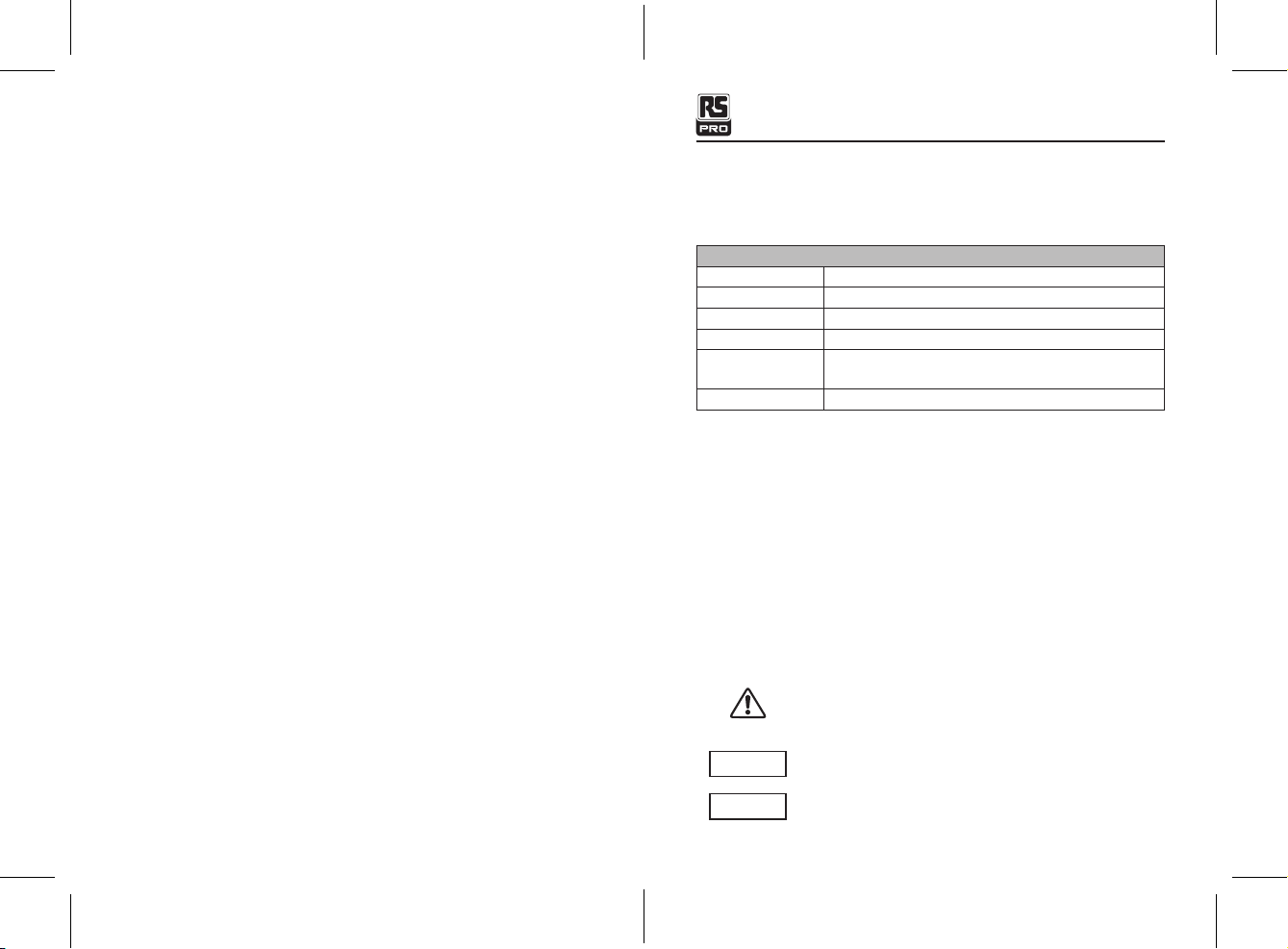
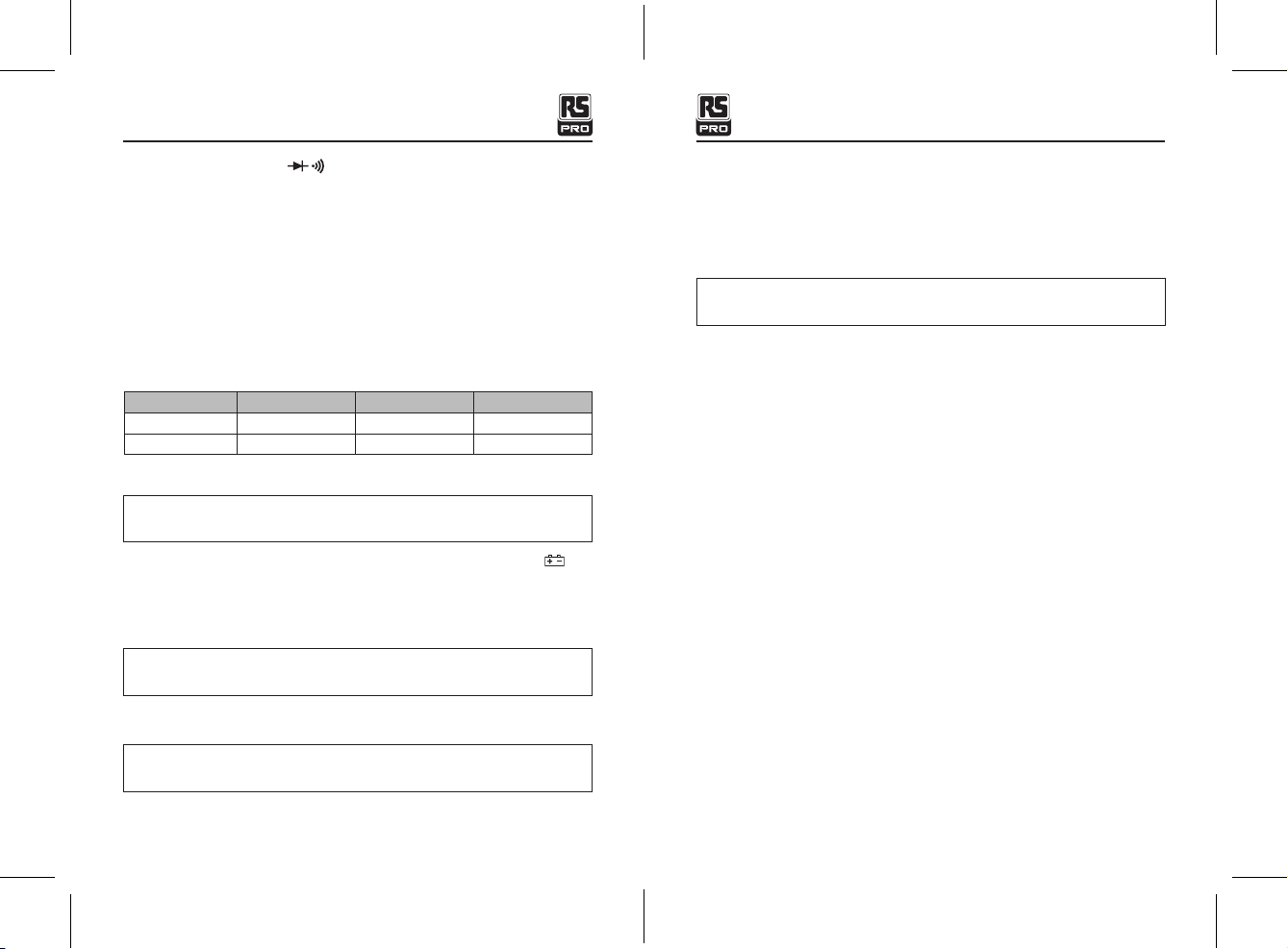
Test de Diode Courant de test de 1 mA maximum, tension de circuit
ouvert à 2 V DC typique
Vérication de continuité Un signal sonore retentira si la résistance est inférieure
à environ 100Ω
L’essai de la batterie 9 V (6 mA); 1.5 V(100 mA)
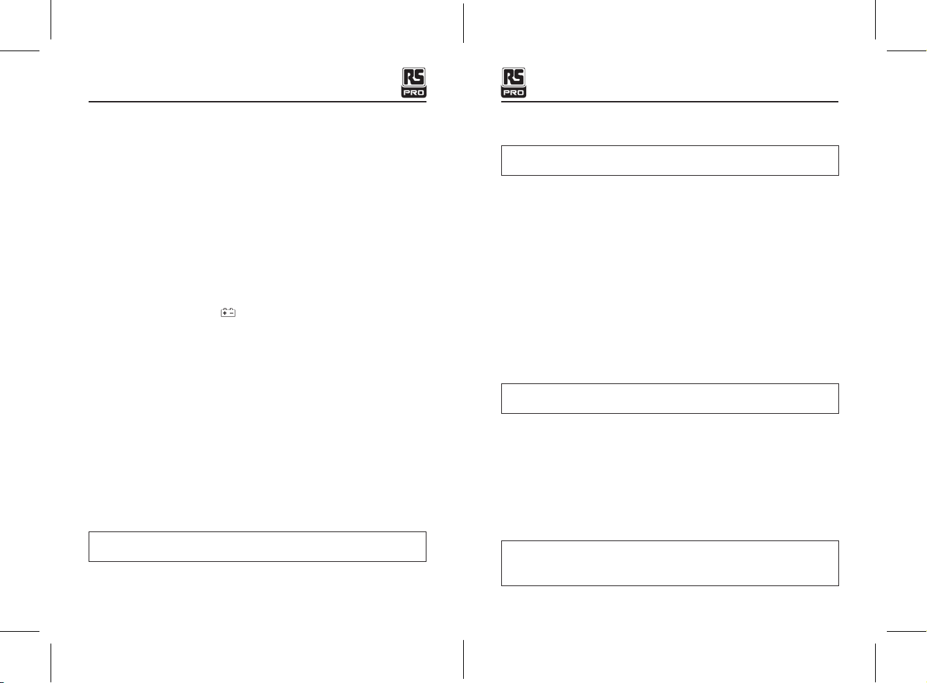
Impedance d’entrée >1 MΩ
Bandepassante ACV 50 Hz à 60 Hz
Chute de tension DCA 200 mV
L’écran 3 ½ chiffres, 2000 points LCD, avec un chiffre de 1,1
Indication de dépassement “OL” estaffiché
Polarité Automatique (pas d'indication de polarité positive);
Signe moins (-) pour la polarité négative.
Taux 2 fois par seconde, nominal
Indication de batteriefaible "" Est affiché si la tension de la batterie chute sous
la tension de fonctionnement
Batterie Une pile de 9 V (NEDA 1604)
Fusibles mA, gammes de μA; 0,2 A / 600 V coup rapide
Une gamme de 10 A / 600 V coup rapide
Température 32 °F à 122 °F (0°C à 50 °C)
Temperature stockée -4 °F à 140 °F (-20 °C à 60 °C)
Humidité <70% de fonctionnement , <80% stockage
Altitude 7000 pieds. (2000) mètres maximum.
Sécurité Pour une utilisation intérieure et conformément à
la Catégorie de surtension II, niveau de pollution 2.
La catégorie II comprend le niveau local, l'appareil,
l'équipement portable, etc., avec des surtensions
transitoires inférieures à la catégorie de surtension III.
5-1.Installation de la batterie
AVERTISSEMENT: Pour éviter les chocs électriques, débranchez les cordons de
toute source de tension avant de retirer le couvercle de la batterie.
• Débranchez les cordons du multimètre.
• Ouvrez le couvercle de la batterie en desserrant la vis à l'aide d'un tournevis cruciforme.
• Insérez la batterie dans le porte-batterie en respectant la polarité.
• Remettez le couvercle de la batterie en place. Fixez avec la vis
AVERTISSEMENT: Pour éviter les chocs électriques, ne faites pas fonctionner le
multimètre tant que le couvercle de la batterie n'est pas en place et bien fixé.
REMARQUE: Si votre lecteur ne fonctionne pas correctement, vérifiez les fusibles et les
piles pour vous assurer qu'elles sont toujours en bon état et qu'elles sont correctement
insérées.
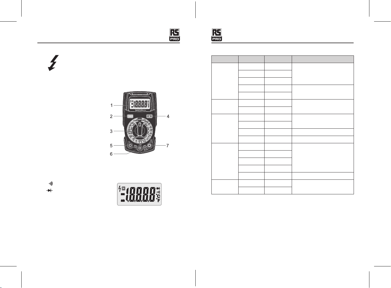
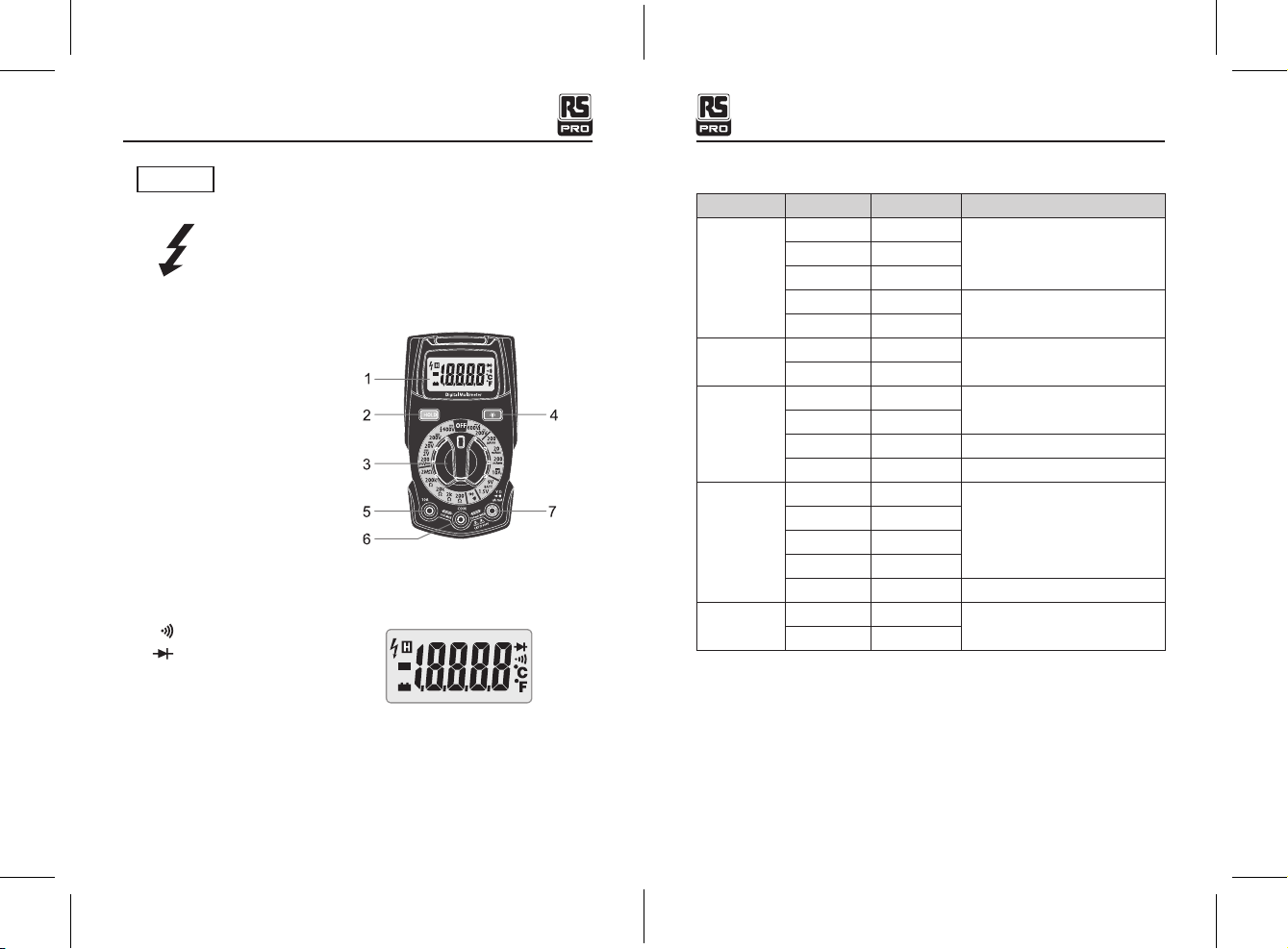
6. Instructions
6-1 Bouton Data Hold
• La fonction Data Hold permet à l'appareil de "geler" une mesure pour référence
ultérieure.
• Appuyez sur le bouton DATA HOLD pour "geler" la lecture sur l'indicateur. L'indicateur
"H" apparaîtra sur l'écran.
• Appuyez sur le bouton DATA HOLD pour revenir au fonctionnement normal.
6-2 Bouton Back Light
• Le bouton BACK LIGHT est utilisé pour allumer ou éteindre le rétro-éclairage. Appuyez
sur le bouton BACK LIGHT pour allumer le rétro-éclairage.
• Appuyez sur le bouton BACK LIGHT pour éteindre le rétro-éclairage.
AVERTISSEMENT: Risque d'électrocution. Les circuits de haute tension, à courant
alternatif et continu, sont très dangereux et doivent être mesurés avec soin.
• TOURNER TOUJOURS l'interrupteur en position OFF lorsque le compteur n'est pas utilisé.
• Si "OL" apparaît sur l'écran pendant la mesure, la valeur dépasse la gamme que vous
avez sélectionnée. Changer pour une gamme plus élevée.
REMARQUE: Sur certaines gammes de tension CA et CC faibles, les cordons n'étant pas
connectés à un périphérique, sur l’écran peut afficher une lecture aléatoire et changeante.
Ceci est normal ,car ceci est causé par la sensibilité d'entrée élevée. La lecture se
stabilisera et donnera une mesure correcte lorsqu'il est connecté à un circuit.
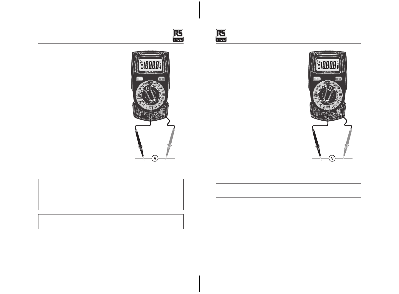
6-3 Mesures de tension DC
ATTENTION: Ne pas mesurer les tensions continues d'un moteur sur le circuit
qui est en train d'être allumé ou éteint. De fortes surtensions peuvent survenir et
endommager le compteur.