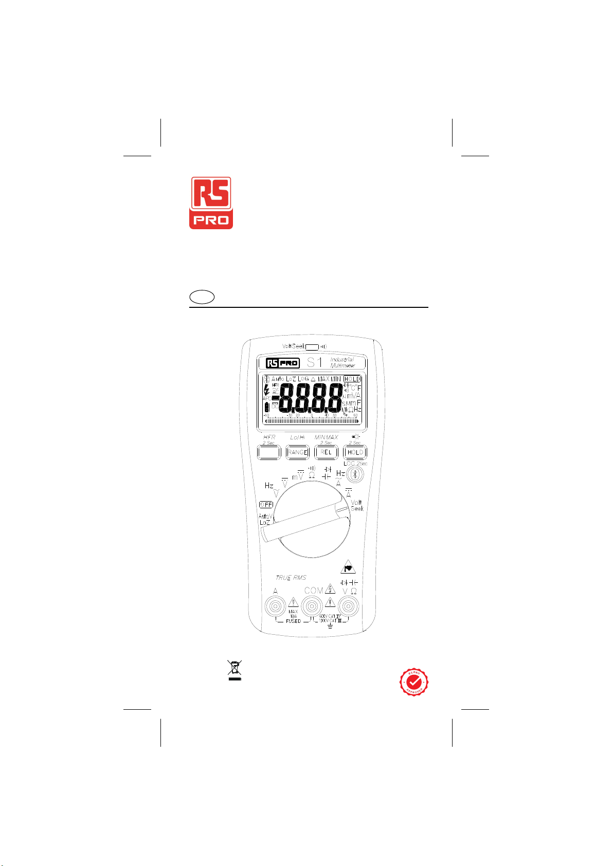
RS PRO S1 User manual

EN
Instruction Manual
S1 & S2 & S3
Digital Multimeter
rspro.com

S1 &S2 & S3 / EN
1
Warning
. . . . . . . . . .
. . . . . . . . . .
. . . . . . . . . .
. . . . . . . .
Safety sheet
. . . . . . . . .
. . . . . . . . . .
. . . . . . . . . .
. . . . . . . .
. . . . . . . . .
Read First
Safety Information
Understand and follow operating instructions carefully. Use the
meter only as .
WARNING
• If the equipment is used in a manner not specified by the
manufacturer, the protection provided by the equipment may
be impaired.
• Always use proper terminals, switch position, and range for
measurements.
• To reduce the risk of fire or electric shock, do not use this
product around explosive gas or in damp locations.
• Verify the Meter operation by measuring a known voltage.
If in doubt, have the Meter serviced.
• Do not apply more than the rated voltage, as marked on
Meter, between terminals or between any terminal and earth
ground.
• To avoid false readings that can lead to electric shock and
injury, replace the battery as soon as low battery indicator
blinks.
• Avoid working alone so assistance can be rendered.
• Do not use the Tester if the Tester is not operating properly
or if it is wet.
• Individual protective device must be used if hazardous live
parts in the installation where the measurement is to be carried
out could be accessible.
• Disconnect the test leads from the test points before changing
the position of the function rotary switch.
• Never connect a source of voltage when the function rotary
switch is not in voltage position.
• When using test leads or probes, keep your fingers behind
the finger guards.
• Use caution with voltages above 30 Vac rms, 42 Vac peak, or
60 Vdc. These voltages pose a shock hazard.
• Remove test lead from Meter before opening the battery door
or Meter case.
• DO NOT USE the test leads when the internal white
insulation layer is exposed.
Warning Safety sheet

S1 &S2 & S3 / EN
2
• DO NOT USE the test leads above maximum ratings of CAT.
environment, voltage and current, that are indicated on the
probe and the probe tip guard cap.
• DO NOT USE the test leads without the probe tip guard cap
in CAT III and CAT IV environments.
• Probe assemblies to be used for MAINS measurements shall
be RATED as appropriate for MEASUREMENT CATEGORY
III or IV according to IEC 61010-031 and shall have a voltage
RATING of at least the voltage of the circuit to be measured.
• Only replace the blown fuse with the proper rating as specified
in this manual.
• Do not attempt a current measurement when the open voltage
is above the fuse protection rating. Suspected open voltage
can be checked with voltage function.
• Never attempt a voltage measurement with the test lead
inserted into the A input terminal.
• Disconnect circuit power and discharge all high-voltage
capacitors before testing resistance, continuity, diodes, or
capacitance.

S1 &S2 & S3 / EN
3
Risk of electric shock
See instruction manual
DC measurement
AC measurement
Bluetooth
HBoth direct and alternating current
Equipment protected by double or reinforced insulation
Low battery
Fuse
Earth
Conforms to EU directives
EApplication around and removal from
hazardous live conductors is permitted
Do not discard this product or throw away.
Attention! Magnets might affect the correct functioning
of cardiac pacemakers and implanted defibrillators.
As a user of such medical devices, keep a sufficient
distance to the magnet.
Symbols as marked on the Meter and Instruction
manual
Unsafe Voltage
To alert you to the presence of a potentially hazardous voltage,
when the Tester detects a voltage ≧30 V or a voltage overload
(OL) in V, mV, AutoV, PV. The symbol is displayed.
Maintenance
Do not attempt to repair this Meter. It contains no user service-
able parts. Repair or servicing should only be performed by
qualified personnel.
Cleaning
Periodically wipe the case with a dry cloth and detergent.
Do not use abrasives or solvents.

S1 &S2 & S3 / EN
4
Introduction
The Meter Description
Front Panel Illustration
1. Volt Seek Light
2. 6,000 count digital display
3. Push-buttons.
4. Rotary switch for turn the Power On / Off and select the function.
5. Input Terminal for Multi-function.
6. Common (Ground reference) Input Terminal.
7. Input Terminal for A.
A COM
Volt Seek
V
Volt Seek Light
LCD Display
Button
Rotary Switch
V,Ω, %,°C Input (or “+”)
Common Input
A Input

S1 &S2 & S3 / EN
5
Features
Function S1 S2 S3
ACV ✓✓✓
DCV ✓✓✓
DC mV ✓✓✓
Frequency ✓✓✓
Resistor ✓✓✓
Continuity ✓✓✓
Diode ✓✓✓
Capacitor ✓✓✓
Bluetooth ✓✓✓
Volt Seek ✓✓✓
AutoV LoZ ✓✓
Data Logger ✓✓✓
HFR ✓✓✓
Backlight ✓✓✓
Bar Graph ✓✓✓
ACA ✓✓
DCA ✓✓
Temperature ✓✓
AC µA/mA ✓
DC µA/mA ✓
PV Voltage ✓

S1 &S2 & S3 / EN
6
Making Basic Measurements
CAUTION
When connecting the test leads to the DUT (Device Under
Test) connect the common test leads before connecting the
live test leads ; when removing the test leads, remove the live
test leads before removing the common test leads.
Measuring Voltage
Preparation and Caution Before Measurement
Observe the rules of Warnings and Cautions.
Dial the switch to select the measuring function.
CAUTION
Do not use the LoZ mode to measure voltages in circuits that
could be damaged by this mode’s low impedance.

S1 &S2 & S3 / EN
7
Measuring PV Voltage
Dial the switch and press the Function button to select the
measuring function.
CAUTION
This function is only available with the dedicated PV test
probe.
Always select correct DC / AC mode to perform high voltage
measurement. This meter will flash symbol and the correct
mode symbol (AC / DC) if the input voltage is different and
dangerous.

S1 &S2 & S3 / EN
8
Measuring Current
Dial the switch and press the Function button to select the
measuring function
Disconnect

S1 &S2 & S3 / EN
9
Measuring Capacitance / Diode
Dial the switch and press the Function button to select the
measuring function
Measuring Continuity / Resistance
Dial the switch and press the Function button to select the
measuring function
Red Black

S1 &S2 & S3 / EN
10
Measuring Temperature °C / °F
Dial the switch and press the Function button to select the
measuring function. (°C / °F)
Volt Seek
Dial the switch to select the measuring function.
Warning
The Volt Seek LED indicates the electric field. If the Volt Seek
LED is not on, voltage could still be present.
Volt
Seek
Do not hold across this
line when sensing the
hazardous voltage.

S1 &S2 & S3 / EN
11
Using the Function
Press the Function button to change the function on the same
switch position.
Range Button
Press Range Button >2 Sec to Enter Auto Range Mode
3
Auto Range Mode
1Manual Range Mode
2
1
Switch range
Switch
Position Function

S1 &S2 & S3 / EN
12
MIN/MAX
The MAX/MIN mode records the min and max input values.
When the input goes below the recorded min value or above the
recorded max value, the meter records the new value. Press
Hold button to pause the recording.
Smart Hold
The meter will beep continuously and the display will flash if the
measured signal is larger than the display reading by 50 counts.
(However, it can not detect across the AC and DC Voltage /
Current).
Press Button > 2 sec
to exit the MIXMAX mode

S1 &S2 & S3 / EN
13
Relative Δ
Press the Relative button to enable/disenable this function.
Backlight
Press the HOLD button over 2 sec to turn on/off Backlight.
Auto Power Off
Wakeup the meter by dialing the switch or pressing any button.
After Specified Time
Without Operation
HOLD

S1 &S2 & S3 / EN
14
Time Setting of Auto Power Off
Press the function button and turn the meter on. Then press the
function button to select the time. The time can be 5 minutes,
10 minutes, 20 minutes, and disabled (OFF).
High Frequency Rejection (HFR)
The High Frequency Rejection mode equip a low pass filter in
the AC measurements. The cut-off frequency (-3dB point) of low
pass filter is 800Hz.
Warning
The hazardous voltage may be present even if the LCD reading
is very low in HFR mode. Verify the voltage again without HFR
mode.

S1 &S2 & S3 / EN
15
Testing LCD Monitor
To turn on the meter after keeping HOLD button down.
Function of LOG Button
12
3
Pressing Bluetooth button while powering-up to select the
mode –Data Logger mode, Manual Saving mode and Clear
memory.

S1 &S2 & S3 / EN
16
Data Logger
The meter can store up to 4000 data in memory.
Press Bluetooth button for more than 2 seconds to activate
Data logger mode. The meter will enter Time interval setting
mode. Press Bluetooth button again to select time interval.
The interval can be 1 second, 5 seconds, 10 seconds, 30
seconds, 60 seconds.
Start to record auto
matically after 2 sec
without operaction.
LOG icon flashes while logging
Time interval setting mode
Caution
All stored data will be cleared next startup. Download the stored
data by App first if needed.

S1 &S2 & S3 / EN
17
Manual Saving Mode
Caution
All stored data are saved until switching to data logger mode or
executing the clear function.
Bluetooth
The meter uses Bluetooth low energy (BLE) V4.0 wireless
technology to transfer the real-time reading and the stored data.
The open-air communication range is up to 10m.
Download “RS Pro Connect” App. Turn on Bluetooth function of
the meter and open “RS Pro Connect” to connect the DMM.
The Bluetooth icon of the meter will freeze on LCD after the
connection establishes successfully.
Flash
To save a reading
Show stored reading
amount for 2 seconds

S1 &S2 & S3 / EN
18
Default Temperature Units Setting
Turn on the meter after keeping Bluetooth button down.
OR
Fuse Replacement

S1 &S2 & S3 / EN
19
Low Battery and Battery Replacement
Replace the battery as soon as the low battery indicator
appears, to avoid false reading.
Refer to the following figure to replace the batteries
CAUTION
Remove test leads from Meter before opening the battery
cover or Meter case
This manual suits for next models
3
Table of contents
Other RS PRO Multimeter manuals

RS PRO
RS PRO LCR 1701 User manual

RS PRO
RS PRO IPM 138N User manual

RS PRO
RS PRO IDM93N User manual

RS PRO
RS PRO IDM-8351 User manual

RS PRO
RS PRO RS-9660B User manual

RS PRO
RS PRO ICM 135R User manual

RS PRO
RS PRO RS-218 User manual

RS PRO
RS PRO RS-9663 User manual

RS PRO
RS PRO ICM 139R User manual

RS PRO
RS PRO IDM201N User manual

RS PRO
RS PRO RS-9519BT User manual

RS PRO
RS PRO RS-9519BT User manual

RS PRO
RS PRO ICM33II User manual

RS PRO
RS PRO RS IDM-20 User manual

RS PRO
RS PRO IDM-8341 Series User manual

RS PRO
RS PRO RS-965T User manual

RS PRO
RS PRO RS-946 User manual

RS PRO
RS PRO RS-9963T User manual

RS PRO
RS PRO RS-9889 User manual

RS PRO
RS PRO RS-989 User manual