Left Side Panel 1 1854-02
Right Side Panel 1 1854-03
Screw Post 18 HFFMFB
Left Cabinet Rail 1 1970-15
Pointed Screw 4 1902-23
Right Cabinet Rail 1 1970-16
Top Panel 1 1854-01
Back Panel 1 1854-04
Bottom Panel 1 1854-05
Locking Cam 18 HFFMFC
Wood Dowel 4 H8MMDWL
Half-Shelf 1 1854-07
Small Machine Screw 4 1854-28
Hinge Bracket (Style 1) 1 1854-29
Hinge Bracket (Style 2) 1 1854-30
Door 1 1854-08
Bushing 2 1854-31
Lock (2 Keys not shown) 1 1854-13
Large Nut 1 1854-24
Caster Bracket 4 1854-10
Barrel Nut 8 1854-23
Bolt 8 1854-27
Lock Washer 8 1854-21
Caster 4 8917-25
Shelf Peg 4 HSFBNZ
Adjustable Shelf 1 1854-06
Drawer 1 1854-09
Q
Q
Q
Q
Q
Q
Q
Q
Q
Q
Q
Q
Q
Q
Q
Q
Q
Q
Q
Q
Q
Q
Q
Q
Q
Q
A
B
C
D
E
F
G
H
I
J
K
L
M
N
O
P
Q
R
S
T
U
V
W
X
Y
Z
AA
MODEL
NUMBER 1854
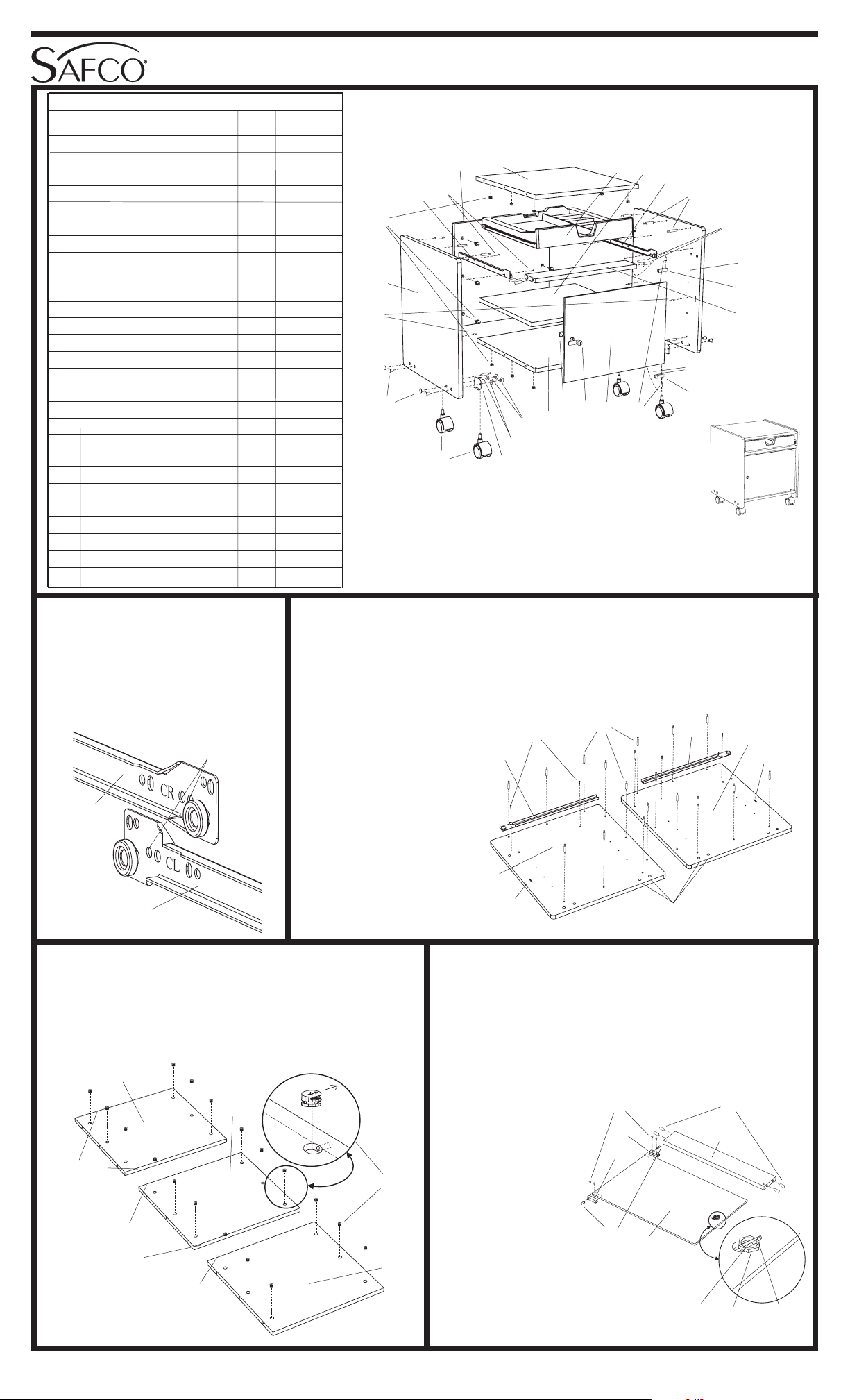
1854-37: 1 of 2; Rev. 1; 12/04
TOOLS REQUIRED: Phillips Screwdriver;
Hammer or Mallet
Machine Floor Stand
For questions or concerns, please call
Safco Consumer Hot Line 1-800-664-0042
available Monday-Friday 8:00 AM to 4:30 PM (Central Time)
(English-speaking operators)
ASSEMBLY INSTRUCTIONS
Safco Products Company, New Hope, MN 55428
LETTER
CODE DESCRIPTION QTY. PART NO.
PARTS LIST
QQ
QQ
Q
D
QQ
QQ
Q
F
Properly identify the two rails
used!
The D Left Cabinet Rail is
stamped “CL” near the roller,
while the F Right Cabinet Rail is
stamped “CR”.
USE THIS HOLE
FOR FRONT
SCREW
1Work on a smooth, clean surface.
Locate the A Left Side Panel and the B Right Side Panel and position them
with the holes up, as shown below. Insert C Screw Posts into the holes
along the top, back and bottom of each panel, and tighten with a screwdriver
(do not overtighten!)
QQ
QQ
QQQ
QQ
Q
QQ
QQ
Q
A
QQ
QQ
Q
B
Attach the D Left
Cabinet Rail to the A
Left Side Panel, with the
roller facing the front
edge, using two E
Pointed Screws (start
with the hole closest to
the roller). Do the same
with the F Right
Cabinet Rail on the B
Right Side Panel.
QQ
QQ
Q
QQ
QQ
QQQ
QQ
Q
QQ
QQ
Q
QQ
QQ
Q
C
QQ
QQ
Q
D
QQ
QQ
Q
EQQ
QQ
Q
F
SLOT
SLOT THROUGH HOLES
The G Top Panel has two finished edges, the H
Back Panel has no finished edges, and the I Bot-
tom Panel has one finished edge. Lay them down
with the large holes facing up. Insert six J Locking
Cams into each panel, with the arrows pointing toward
the nearest SIDE edge.
Insert the four K Wood Dowels into the holes in the
ends of the L Half-Shelf. Tap with a hammer or mallet
until they are fully seated.
Using two M Small Machine Screws each, attach the
N and O Hinge Brackets to the corners of the P
Door, opposite the large hole. Make sure that the
posts on the Brackets are closest to the corner. Slip a
Q Bushing over each post.
QQ
QQ
QQQ
QQ
Q
23QQ
QQ
Q
QQ
QQ
Q
QQ
QQ
Q
QQ
QQ
QQQ
QQ
Q
QQ
QQ
Q
J
QQ
QQ
Q
FINISHED
EDGES
NO
FINISHED
EDGES
ONE
FINISHED
EDGE
QQ
QQ
Q
G
QQ
QQ
Q
H
QQ
QQ
Q
I
QQ
QQ
Q
QQ
QQ
Q
From the face of the
Door OPPOSITE the
screws in the Hinge
Brackets, insert the R
Lock through the large
hole, and fasten with
the S Large Nut so
that the pawl points
straight out to the
side. Once securely
fastened, turn the
Lock with the Key so
the pawl is parallel to
the edge.
QQ
QQ
Q
QQ
QQ
Q
QQ
QQ
Q
P
QQ
QQ
Q
K
QQ
QQ
Q
L
QQ
QQ
Q
QQ
QQ
Q
N
QQ
QQ
Q
O
QQ
QQ
Q
M
QQ
QQ
Q
Q
QQ
QQ
Q
RQQ
QQ
Q
SLOCK
PAWL
ASSEMBLED UNIT
MODEL 1854
QQ
QQ
Q
QQ
QQ
Q
QQ
QQ
Q
A
QQ
QQ
Q
B
QQ
QQ
Q
C
QQ
QQ
Q
DQQ
QQ
Q
EQQ
QQ
Q
F
QQ
QQ
Q
G
QQ
QQ
Q
H
QQ
QQ
Q
I
QQ
QQ
Q
JQQ
QQ
Q
K
QQ
QQ
Q
L
QQ
QQ
Q
M
QQ
QQ
Q
N
QQ
QQ
Q
O
QQ
QQ
Q
Q
QQ
QQ
Q
P
QQ
QQ
Q
R
QQ
QQ
Q
S
QQ
QQ
Q
T
QQ
QQ
Q
V
QQ
QQ
Q
U
QQ
QQ
Q
X
QQ
QQ
Q
Y
QQ
QQ
Q
Z
QQ
QQ
Q
AA
QQ
QQ
Q
QQ
QQ
Q
QQ
QQ
Q
QQ
QQ
Q
W


