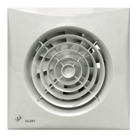
S&P decor-100 DC User manual

DECOR-100 "DC"
User instructions
Instrukcja obs³ugi

Fig. 1
Fig. 2

Fig. 3
Fig. 4
Fig. 5

Fig. 6
Fig. 8
Fig. 7 Fig. 9

POLSKI
Wentylatory osiowe DECOR-100 DC
Wentylatory osiowe, wyciagowe serii DECOR-
100saproduktamiwysokiejjakosciwykonanymi
zgodnie z miedzynarodowym standardem ISO
9001. Wszystkie komponenty sa sprawdzane,
a produkt finalny kontrolowany pod koniec
procesu produkcji.
Po otrzymaniu wentylatora prosimy o
sprawdzenie :
1- Czy wielkosc wentylatora jest
prawidlowa.
2- Czy model wentylatora jest prawidlowy.
3- Czy dane na tabliczce znamionowej
odpowiadaja parametrom zadanym
(napiecie, czestotliwosc pradu itd.)
Podlaczenie instalacji elektrycznej
powinno byc wykonane przez
wykwalifikowany i upowazniony do tego
personel, zgodnie z odpowiednimi regulacjami
prawnymi obowiazujacymi w
Polsce.
Instalacja
UWAGA! Przed rozpoczeciem montazu
wentylatora odlacz zasilanie pradu od
instalacji elektrycznej !
Fig. 1:
1: Kratka ochronna
2: Sruba mocujaca
3: Kostka przylaczeniowa
4: Wylot z zaluzja
5: Doprowadzenie kabla
Wentylatory typu DECOR-100 sa
przystosowane do montazu w scianie
lub suficie i moga byc podlaczane do
indywidualnego lub centralnego systemu
wentylacyjnego (Fig. 2).
Urzadzenie moze byc przymocowane do
sciany przy uzyciu zalaczonych 4 kolków
rozporowych i wkretów.
W przypadku montazu bezposrednio w
scianie lub suficie nalezy wykonac otwór o
srednicy 105 mm. Jezeli wentylator ma byc
zmontowany z kanalem wentylacyjnym
nalezy uzyc standardowego kanalu o
srednicy 100 mm.
Odkrecajac sruby mocujace nalezy zdjac
kratke (1).
Nalezy sie upewnic, czy kanal
wentylacyjny nie jest zablokowany i czy
wirnik wentylatora obraca sie bez przeszkód.
Mocowanie wentylatora powinno byc
pewne, zapobiegajace powstawaniu wibracji
i umozliwiajace swobodne obracanie
wirnika. Nalezy sprawdzic, czy zaluzje
otwieraja sie swobodnie. Kabel zasilajacy
nalezy doprowadzic przez wejscie (5) i
zamontowac do sciany tak aby sruba (2)
byla powyzej.
Podlaczenie elektryczne wykonac zgodnie
z nizej przedstawionym opisem, nastepnie
zamontowac kratke ochronna (1) dokrecajac
ja sruba mocujaca (2).
Instalacja elektryczna
Wentylator DECOR-100 jest przeznaczony
do zasilania pradem zmiennym,
jednofazowym (napiecie i czestotliwosc jak
na tabliczce znamionowej). Posiadaja
zabezpieczenie przed porazeniem pradem
w klasie II , nie wymagaja podlaczenia
uziemienia.
Przewód elektryczny musi byc
doprowadzony do wentylatora przez
wejscie (5). Przewód nalezy podlaczyc
zgodnie ze schematem odpowiednim dla
wybranego modelu.
DECOR-100 CZ/DC
Instalacje elektryczna nalezy wykonac
zgodnie z nastepujacymi schematami:
Fig.3: Podlaczenie wentylatora do wylacznika
swiatla.
Fig.4: Podlaczenie wentylatora do
niezaleznego wylacznika.
˛
´
·
˛
˛
˛
´´
´
´
˛˛
˛˛´´˛
˛
´
´·
˛˛
´˛˛
´
´˛
˛
·
´
´´˛
˛·´
´·´˛
˛
´
·´
´·´
´·´
··´´
´
˛˛´·´
˛˛
·˛
˛
´´
˛
´
·˛·´·
˛˛
·´´
´´
´·
˛
˛
˛
´´
·˛
´
˛˛
˛˛´´
·
˛
˛
˛
´
´
´
·´˛
˛·´
˛˛

DECOR-100 CRZ/DC
Powyzsze modele wyposazone sa w
wylacznik czasowy (timer) regulowany
pozwalajacy na prace wentylatora przez
pewien czas po wylaczeniu (fig.5).
Fig. 6 przedstawia schemat podlaczenia do
wylacznika swiatla.
Aby ustawic wielkosc opóznienia przekrec
potencjometr na plytce (fig.7):
- Aby skrócic czas pracy wentylatora -
w lewo (min. 1 minuty)
- Aby wydluzyc czas pracy wentylatora - w
prawo (max. 30 minut)
DECOR-100 CHZ/DC
Powyzsze modele sa wyposazone w
elektroniczny higrostat regulowany od 60
do 90% RH (%wilgotnosci wzglednej), oraz
wylacznik czasowy regulowany od 2 do
20 minut.
Obsluga
Sposób 1: Praca automatyczna (fig.8)
W tym trybie hygrostat powoduje
automatyczne wlaczenie wentylatora po
przekroczeniu w pomieszczeniu poziomu
wilgotnosci ustawionego pokretlem.
Wentylator wylaczy sie automatycznie po
spadku wilgotnosci ponizej ustawionego
poziomu i po czasie ustawionym wylacznikiem
czasowym.
Sposób 2: Praca automatyczna podobnie
jak w przypadku pierwszym ale z
mozliwoscia uruchamiania wentylatora
wylacznikiem swiatla (fig.6), gdy poziom
wilgotnosci w pomieszczeniu jest nizszy
od ustawionego. W tym przypadku, po
wylaczeniu wylacznika swiatla wentylator
pracuje przez okres ustawiony wylacznikiem
czasowym.
UWAGA: W przypadku, gdy poziom
wilgotnosci wzglednej w pomieszczeniu
jest wyzszy niz ustawiony na higrostacie,
wentylator wlacza sie automatycznie
ignorujac dzialania
manualne tzn.
wentylator nie moze byc zatrzymany przy
uzyciu wylacznika.
Wymagany poziom wilgotnosci jest
ustawiany przez przekrecenie potencjometru
”% Hr” umieszczonego na plytce (fig.9)
dostepnej pod kratka (1).
- Aby zwiekszyc ustawienie wilgotnosc -
przekrec w lewo (min.60 %)
- Aby zmniejszyc ustawienie wilgotnosc
- przekrec w prawo (max. 90%)
Aby ustawic wielkosc opóznienia nalezy
przekrecsc potencjometr “t min.” na plytce
(fig.9):
- Aby skrócic czas pracy wentylatora -
w lewo (min. 2 minuty)
- Aby wydluzyc czas pracy wentylatora - w
prawo (max. 20 minut)
Konserwacja
Przed rozpoczeciem czynnosci
konserwacyjnych nalezy odlaczyc zasilanie
od wentylatora.
Wentylatory wymagaja tylko okresowego
czyszczenia przy uzyciu sciereczki i
delikatnego detergentu.
Montaz wentylatora w sposób niezgodny z
instrukcja, oraz praca wentylatora w stanie
zdemontowanym sa zabronione. Próby
samodzielnej naprawy powoduja utrate
gwarancji.
W przypadku wystapienia uszkodzen
urzadzenia prosimy o kontakt z punktem
sprzedazy.
S&P zastrzega sobie prawo do zmian
parametrów konstrukcyjnych bez
uprzedzenia.

ENGLISH
DECOR-100 DC Axial Extractor Fans
The DECOR-100 extractor fan range is
manufactured to the high standards of
production and quality as laid down by the
international Quality Standard ISO 9001.
All components have been checked and
every one of the final products will have
been individually tested at the end of the
manufacturing process.
On reciept of the product we recommend
that you to check the following :
1- That it is the correct size.
2- That it is the correct model.
3- That the details on the rating label are
those you require: voltage, frequency
...
The installation must be carried out in
accordance with the electrical standards
in force in your country.
Installation
IMPORTANT: Before installing and wiring
the unit, ensure that the main supply is
disconnected.
Fig. 1:
1- Protection grille
2- Fixing screw
3- Connection terminals
4- Outlet with backdraught shutter
5- Cable entry
The DECOR-100 is suitable for wall or
ceiling mounting and can either discharge
directly to the outside or via an individual or
central ducting system (see Fig. 2).
The unit can be mounted on the wall or
ceiling using the 4 rubber blocks and the
screws provided.
Make a hole in the wall or ceiling of 105
mm dia.
If the unit is to be installed with individual
ducting, use a standard 100 mm dia.
duct.
Undo the two grille fixing screws (1).
Ensure that there are no obstructions to the
airflow and that the impeller turns freely.
Fix the extractor to the wall in such a way
that it is not distorted in order to avoid
noise generation or problems with the
rotation of the impeller. Make sure that the
backdraught shutter opens freely and has
not being damaged in transit. Introduce
the mains cable through the cable entry (5)
and fix it to the wall so that the fixing screw
(2) is above.
Connect the electrical wiring as set out below
and then mount the protection grille (1) and
tighten the screw (2).
Electrical connection
The DECOR-100 is an extractor desig-ned
for a single phase supply, with voltage and
frequency as indicated on the rating plate
of the unit. The units are manufactured with
double electrical insulation
(Class II) and therefore they do not need an
earth connection.
The electrical installation must include a
double pole switch with a contact clearance
of at least 3 mm.
The electrical cable must enter the DECOR-
100 through the cable entry (5).
Once the cable has been introduced proceed
using the electrical wiring diagram applicable
to the selected model.
DECOR-100 CZ/DC
For these models use the following
diagrams:
Fig.3: Switching the extractor through the
light switch.
Fig.4: To switch the fan through an
independent switch.
DECOR-100 CRZ/DC
These models are provided with an adjustable
timer. The timer allows the fan to continue to
operate for the selected period after the
switch has been turned off (fig.5).
Fig.6 shows how to connect the fan with
timer utilising the same switch as for the
lighting.
To set the timer, turn the potentiometer on
the printed circuit board (fig. 7):
- To reduce the «run on» time, turn

anticlockwise (min. 1 minutes)
- To increase the «run on» time , turn
clockwise (max: 30 minutes).
DECOR-100 CHZ/DC
Models provided with an electronic humidistat
which can be adjusted from 60% to 90 % RH
(relative humidity) and with a timer, adjustable
between 2 and 20 minutes.
Operation
Case 1: Automatic operation (fig.8)
In automatic operation, the humidistat
causes the extractor to operate automatically
when the humidity level in the room is higher
than the set level. The extractor will stop
automatically when the humidity drops below
the selected level and after the selected
period set on the timer.
Case 2: Automatic operation as in case 1
with the facility to override the hygrostat by
means of the light switch (fig.6), when the
humidity level in the room is lower than the
selected level. In this case, the extractor
continues to operate for the selected period
set on the timer after the switch light has
been switched off.
ATENTION: When the himidity rate is
above the selected value, the automatic
option takes precedence over the manual
and the unit cannot then be switched off
using a switch.
The desired humidity level is selected
by means of a potentiometer “% Hr”
positioned on the printed circuit board (fig.
9) and accessible once the grille (1) has
been removed.
- To increase the humidity setting turn
anticlockwise (min.60 %)
- To reduce the humidity setting turn
clockwise (max. 90 %)
To set the timer, turn the potentiometer “t
min.” on the printed circuit board (fig. 9):
- To reduce the «run on» time, turn
anticlockwise (min. 2 minutes)
- To increase the «run on» time , turn
clockwise (max: 20 minutes).
Maintenance
The extractor fan only requires periodical
cleaning using a cloth lightly impregnated
with a soft detergent.
After Sales Service
We recommend you not to try to dismantle or
remove any other parts than those mentioned
as any tampering would automatically cancel
the S&P guarantee. If you detect any fault,
contact your S&P dealer.
S&P reserves the right to alter specifications
without notice.
Other manuals for decor-100 DC
4
Table of contents
Languages:
Other S&P Fan manuals

S&P
S&P RESPIRO 100 User manual

S&P
S&P PCD80XHP User manual

S&P
S&P STXD Series User manual

S&P
S&P ARTIC TOWER M Technical Document

S&P
S&P CTBH ECOWATT User manual

S&P
S&P UVF ECOWATT Series User manual

S&P
S&P Compact Sp Series Operation manual

S&P
S&P TD-SILENT Series User manual

S&P
S&P TD-160/100 N SILENT User manual

S&P
S&P HV-230 Manual

S&P
S&P TURBO-451 CN User manual

S&P
S&P SILENT DUAL Series User manual

S&P
S&P ALTAIR 120 H User manual

S&P
S&P CACB-HP 12 User manual

S&P
S&P ILB-ILT ILT/4-285 User manual

S&P
S&P CUL507-18 User manual

S&P
S&P TD-1300/250 SILENT 3V User manual

S&P
S&P OZEO FLAT H ECOWATT User manual

S&P
S&P Decor-200 CRZ User manual

S&P
S&P ERV TRC1600 P1 Instruction manual