S&S Precision LIFTR Series User manual
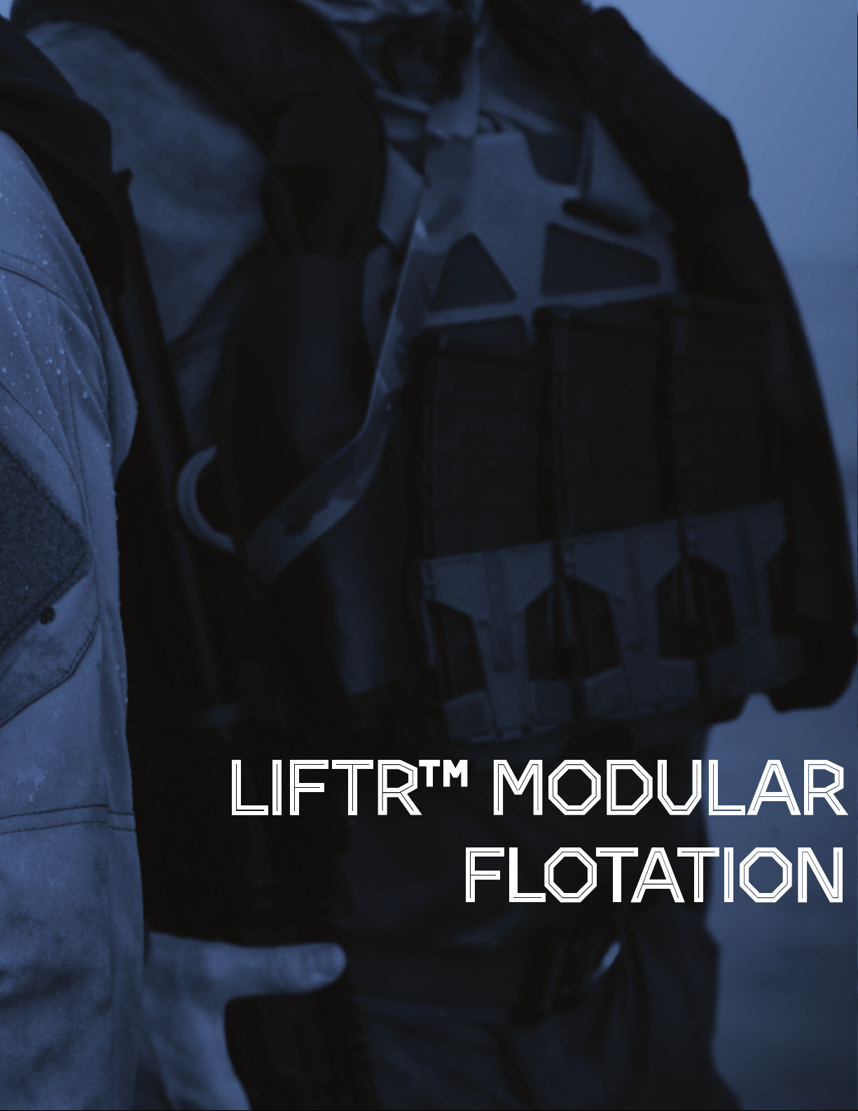
LIFTR™ MODULAR
FLOTATION
LIFTR™ SPECIFICATIONS, CARRIER
ATTACHMENT AND DRAEGER
REBREATHER INSTRUCTIONS

LIFTR™ SPECIFICATIONS
LiftR-40 Modular Flotation
Sensitive Business Document. Proprietary to S&S Precision
0ft 40lbs
10ft 34lbs
20ft 27lbs
30ft 21lbs
Lift
Depth
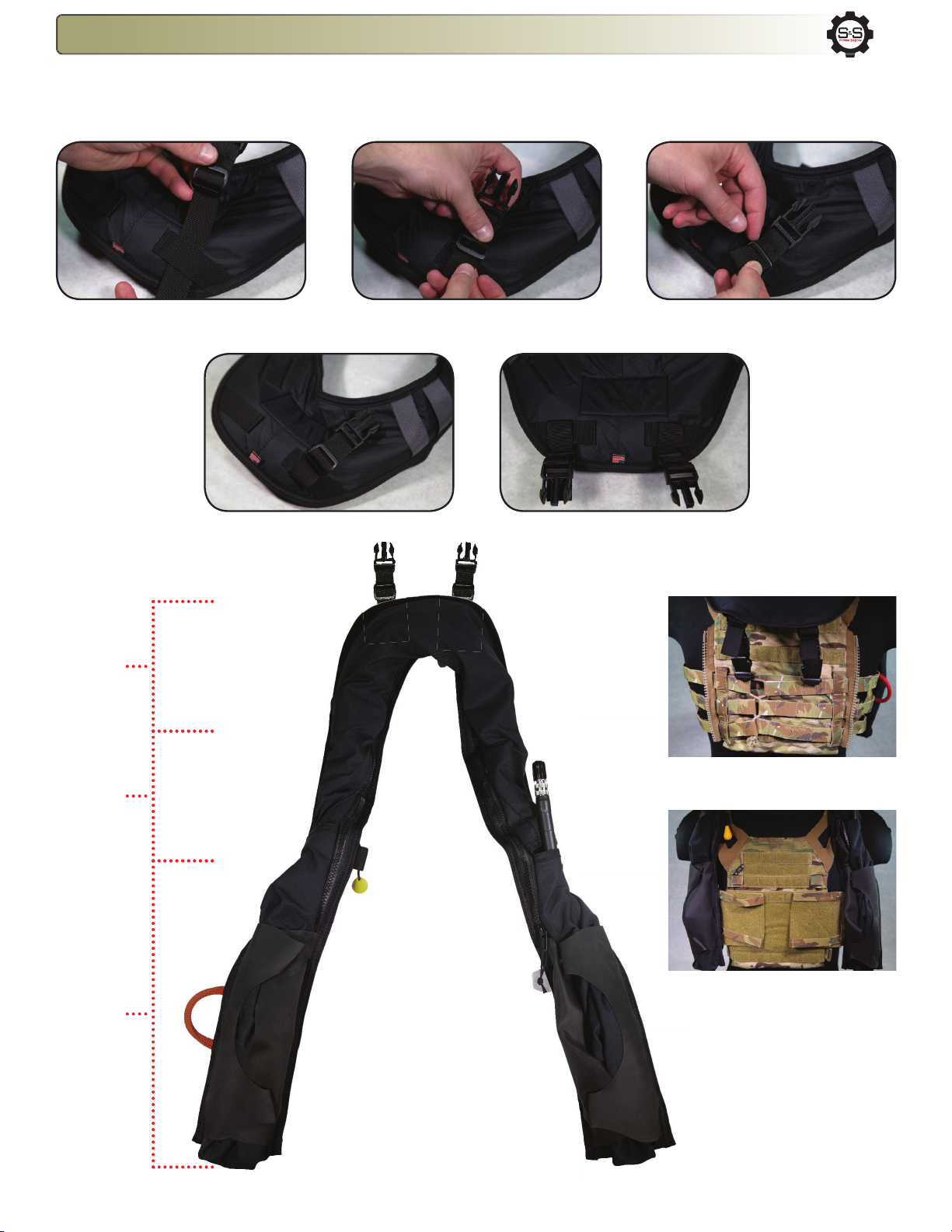
Depth/Lift Requirements:
The LiftR-40 is intended to be used in surface and subsurface operations. The LiftR-40
is attached to existing combat equipment by slipping it on and over the shoulder
straps and cummerbund of the operator’s plate carrier. The LiftR-40 is self-packing and
modular to t most brand’s plate carriers. The LiftR-40 provides the appropriate amount
of lift necessary to bring a diver/swimmer to the surface and oat them in a face up
orientation. The Depth/Lift Requirements are assuming the operator is wearing a full
operational equipment load.

LiftR-40 Modular Flotation
Sensitive Business Document. Proprietary to S&S Precision
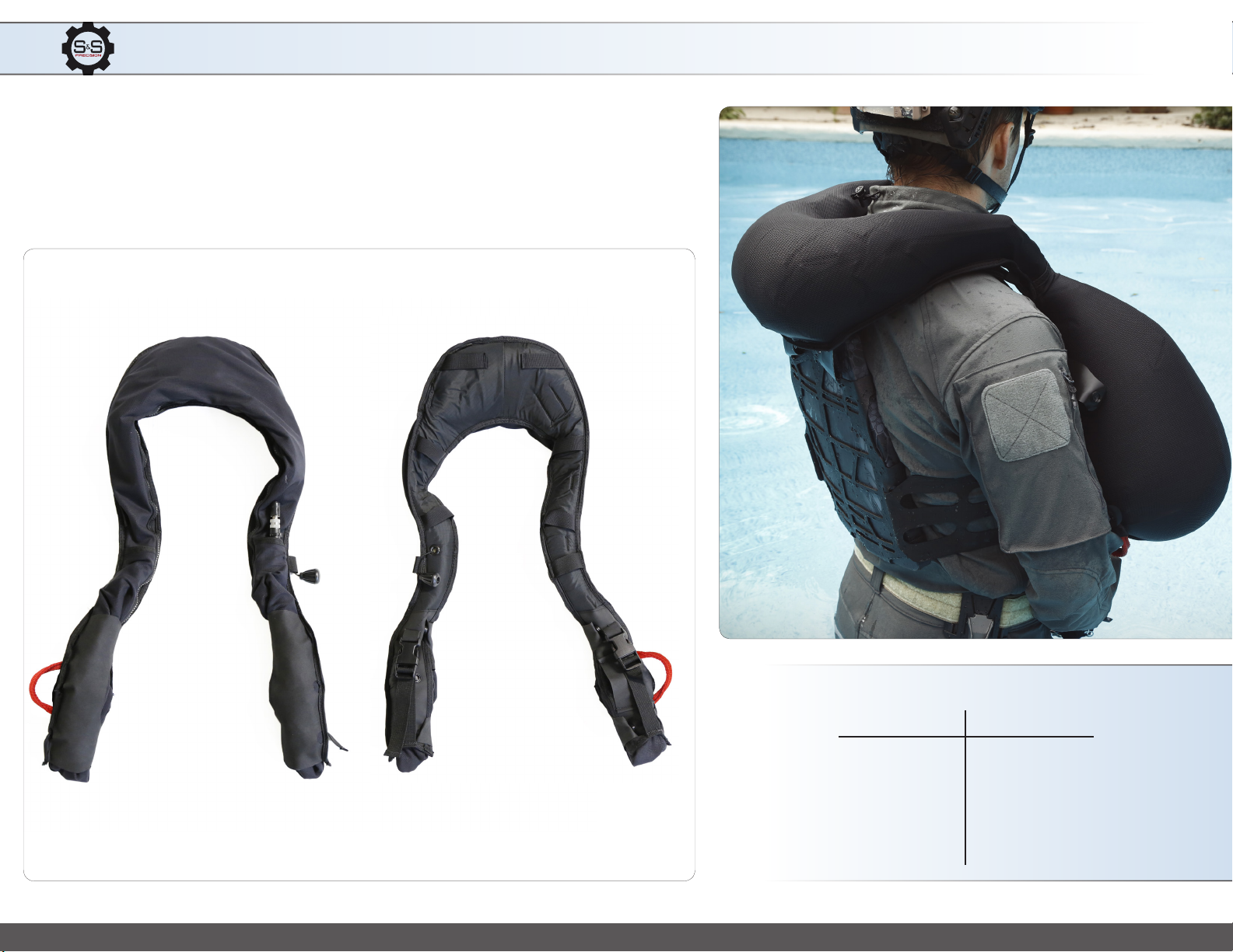
Manual Air Dump/
Over Ination Valve
Oral Ination Tube
Actuator Pull Handle
CO2 Actuator
Capped = Manual Ination
Uncapped = Automatic Ination
LiftR-40 Attachments
Sensitive Business Document. Proprietary to S&S Precision
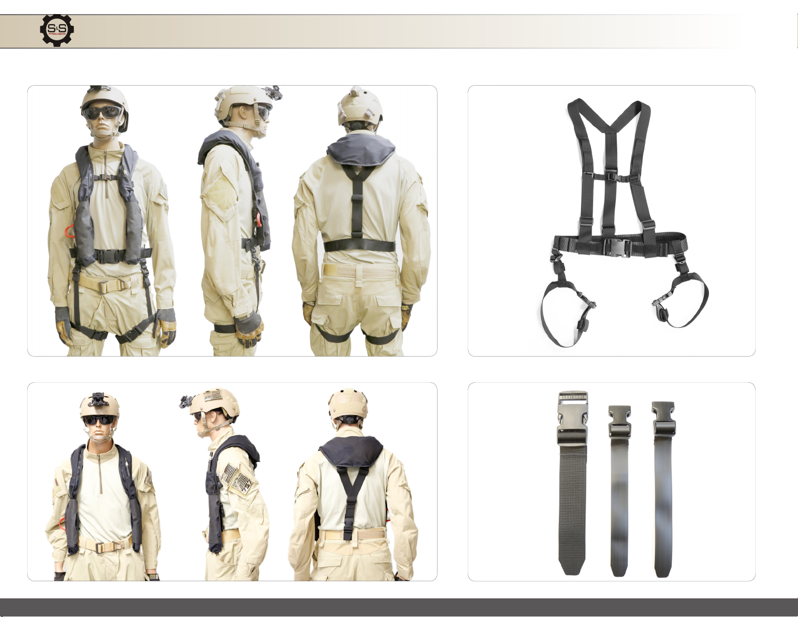
Harness Attachment System
Expedient Attachment System
LiftR-40 Attachments
Sensitive Business Document. Proprietary to S&S Precision
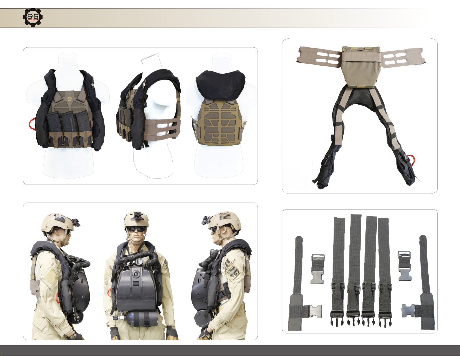
Plate Frame Attachment System
Dräger Plate Frame Attachment System
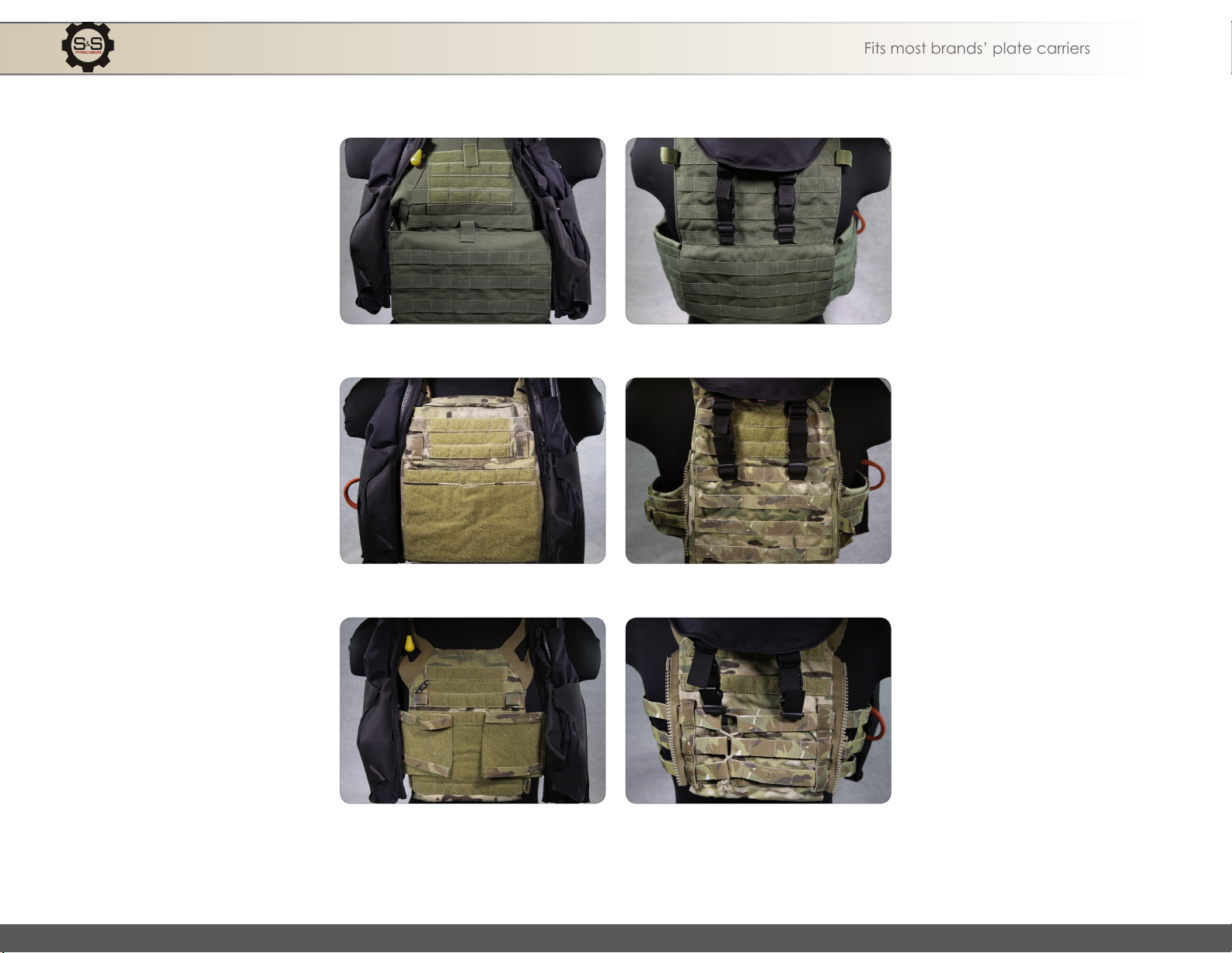
LiftR-40 with Alternative Plate Carriers
Sensitive Business Document. Proprietary to S&S Precision
LBT 6094
CRYE PRECISION AVS
CRYE PRECISION JPC
Fits most brands’ plate carriers
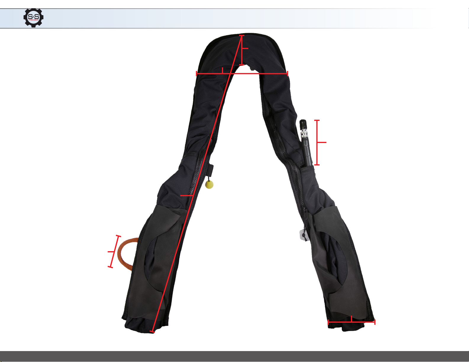
LiftR-40 Collar Measurements
Sensitive Business Document. Proprietary to S&S Precision
29”
4”
4”
2.5”
8”
5”
57” total length
2.3 lbs with cartridge

LiftR-40 General Materials and Components
Sensitive Business Document. Proprietary to S&S Precision
Materials
Components
Acetal
Nexcel
Nexlon
Nylon 6/6
Elastomeric Resin
• Slide Corrosion Resistant Zippers & Zipper Slide
• 1” Nylon Webbing 5000 Series
• Nylon Velcro Loop and Hook
• Oral Valve Halkey
• 3/8” Detonator
• CO2 Manifold
• Oral Ination Tube
• Water-Activated Actuator
• 210 Heat Seal Nylon
• Rip Stop 70 Denier
• 1/8 Close Cell Foam
• Brass Grommets
• Overpressure Valve
• Single Release Buckles
• Snap Buttons

PF-M™ INSTRUCTIONS
LiftR 40™ (LR-0001BK)
Attachment Instructions - PF-M™ Attachment Instructions - PF-M™
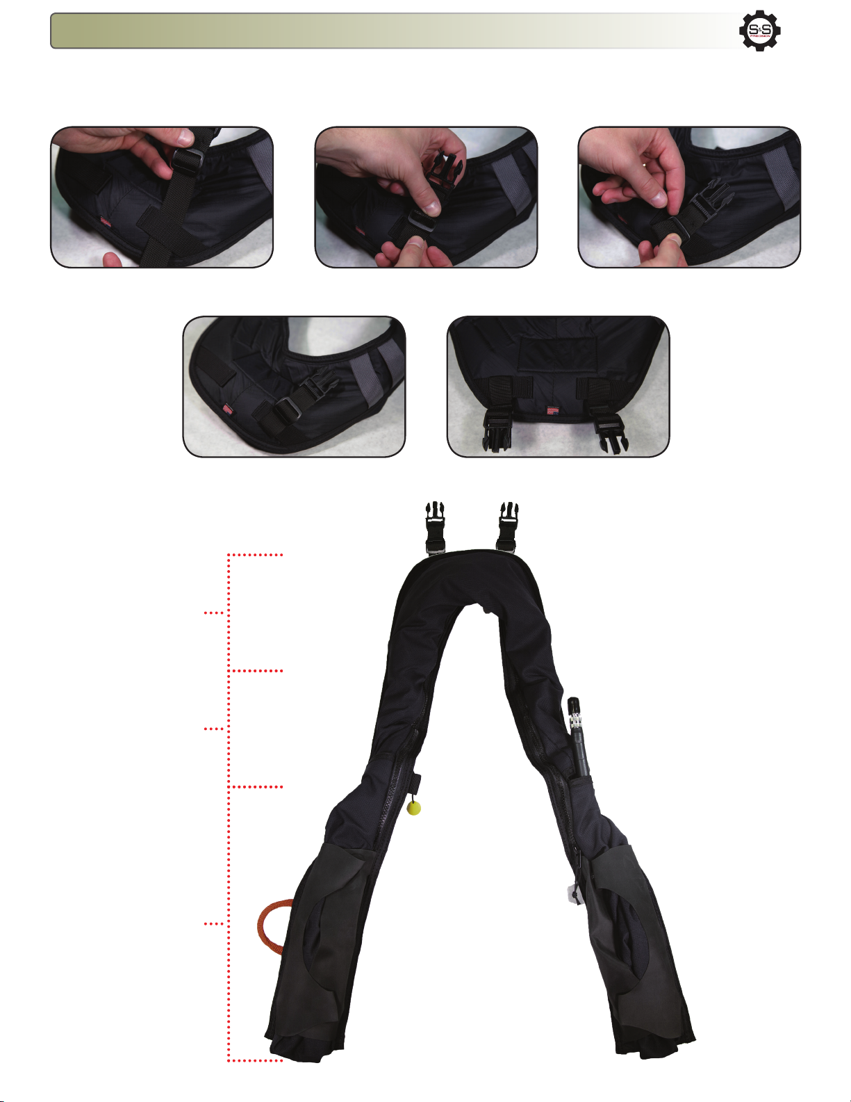
The LiftR™ comes with a set of male and female tri-glides which should be attached to the back of the LiftR™ and to the back of the carrier rst before
attaching the LiftR™ itself.
1. With the tri-glide facing you, weave the tri-glide strap
through one of the loops on the back of the LiftR™ as shown.
2. Feed the end of the strap back up through the tri-glide. 3.Pass the strap back down through the tri-glide and tighten
to secure tri-glide.
4. Properly attached tri-glide. 5. Repeat steps for second tri-glide and adjust tri-glides
so that they are pointed towards the back of the LiftR™.
Step 1: LiftR 40™ Male Tri-glide Attachment Instructions
Back
Front
Shoulder
Straps

LiftR 40™ (LR-0001BK) Attachment Instructions - PF-M™
The LiftR™ is an inatable otation system used in surface and subsurface operations, providing the appropriate amount of lift necessary to bring a diver/swimmer to the surface and oat them
in a face-up orientation. It is attached to existing combat equipment by slipping it on and over the shoulder straps and cummerbund of the operator’s plate carrier. The LiftR™ is self-packing
and will t most plate carriers. These instructions specically relate to the S&S Precision PlateFrame - Modular (PF-M™) carrier.
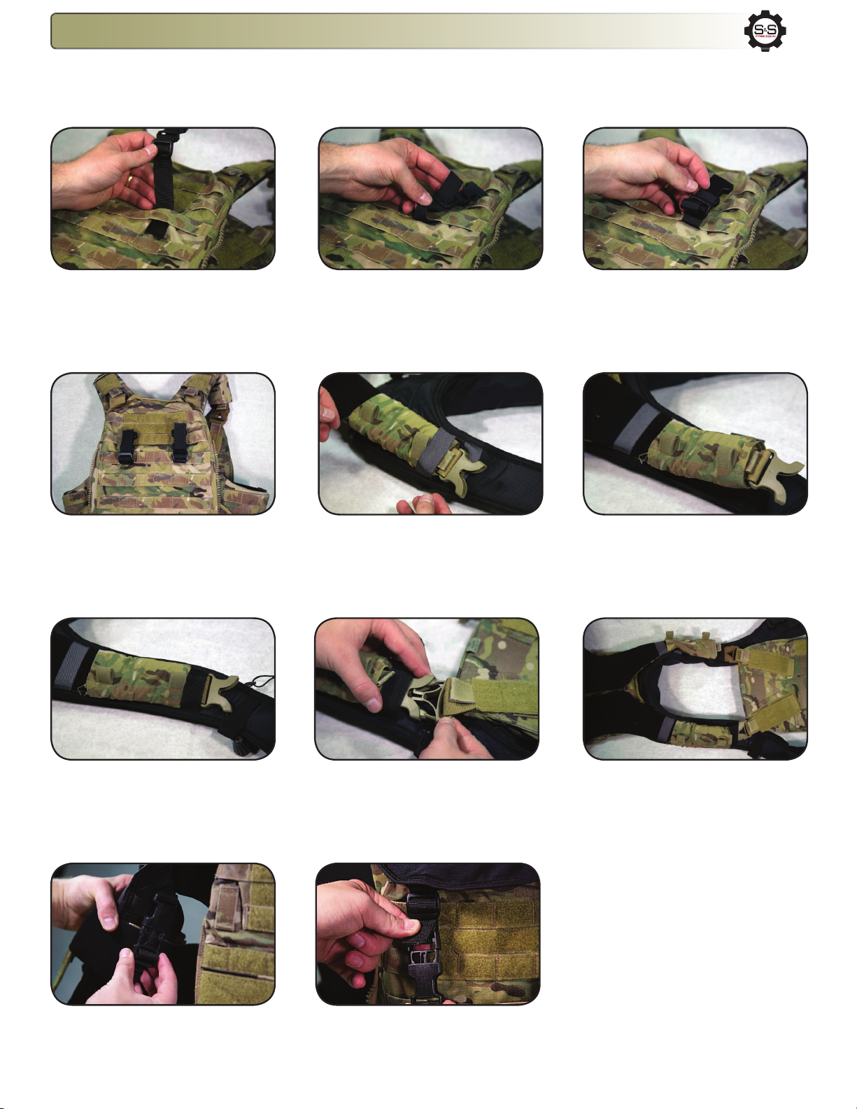
READ BEFORE USE
5. Reconnect the male and female cummerbund buckles.
Slide the arm of the LiftR so it sits close to the buckle.
REPEAT STEPS 4-5 for opposite cummerbund.
6. The LiftR™ Modular Flotation is now attached to the
PlateFrame™ Modular.
3. Continue to insert the shoulder strap through the LiftR,
skip the last strap indicated above. Reconnect the male
and female shoulder buckles. REPEAT STEPS 1-3 for
opposite shoulder strap.
4. Insert the cummerbund through the LiftR strap shown.
Tighten to secure.
SKIP
1. Begin assembly by locating the retention straps
indicated above. These straps will be used to attach the
LiftR™ Modular Flotation to the PlateFrame™ Modular.
2. Disconnect the shoulder and cummerbund PF-M
buckles. Skipping the rst strap indicated above, insert the
male buckle through the LiftR as shown.
SKIP
SKIP

LBT 6094 CARRIER
ATTACHMENT
INSTRUCTIONS

LiftR 40™ (LR-0001BK) Attachment Instructions - LBT 6094
The LiftR™ comes with a set of male and female buckles which should be attached to the back of the LiftR™ and to the back of the carrier first before
attaching the LiftR™ itself.
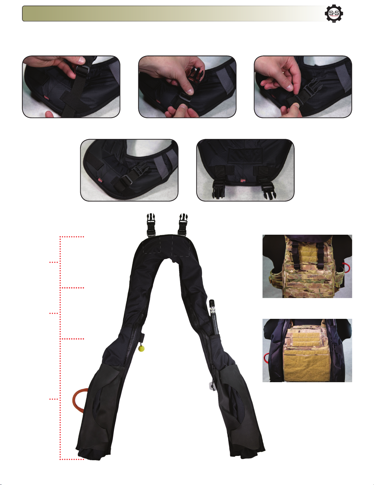
2. With the tri-glide facing you, weave the buckle strap through
one of the loops on the back of the LiftR™ as shown.
3. Feed the end of the strap back up towards the tri-glide. 4.Secure the buckle strap fully through tri-glide and tighten.
2. Feed the strap back up through the tri-glide and tighten. 3. Repeat same process with the other buckle strap and
then pull buckles so they are facing down.
Step 1: LiftR 40™ Male Buckle Attachment Instructions
Back
Front
Shoulder
Straps
Back Attachment
Front Attachment

LiftR 40™ (LR-0001BK) Attachment Instructions - LBT 6094
The LiftR™ is an inflatable flotation system used in surface and subsurface operations, providing the appropriate amount of lift necessary to bring a diver/swimmer to the surface and float them
in a face-up orientation. It is attached to existing combat equipment by slipping it on and over the shoulder straps and cummerbund of the operator’s plate carrier. The LiftR™ is self-packing
and will fit most plate carriers. These instructions specifically relate to the LBT 6094 carrier.
1.Weave the included female buckle straps into the MOLLE/
PALS webbing on the back of the carrier. Buckle ride height
can be adjusted to preference once the LiftR is assembled.
2. Feed the strap back up through the tri-glide and tighten. 3. Feed the end of the strap back through the other end
of the tri-glide to secure the buckle in place.
Step 2: LiftR 40™ LBT 6094 Attachment Instructions
7. Pull strap completely through loop as shown. 8. Begin weaving the end of the strap through the tri-
glide on the back plate bag.
9. Continue to weave the strap down through the tri-glide
and pull excess length through.
12. Repeat with other shoulder strap and adjust to
preference if needed.
11. Continue to pull strap through LiftR and fasten Velcro.10. Pass strap back up through the grey webbing loop
and begin feeding the excess length through.
13. Feed the LiftR’s cummerbund strap under the
carrier’s cummerbund and fasten side-release buckle.
14. Attach the LiftR’s back section to the buckles from
steps 1-4 and adjust straps as needed.
4. Repeat with the other buckle. Be sure to space the
buckles two MOLLE/PALS columns apart, centered on
the carrier..
5. Detach shoulder straps from back plate
bag. Position front plate bag over the LiftR
with straps lying flat. Pass shoulder strap
through 2nd webbing loop on the front of the LiftR. Be
sure the Velcro Hook is facing down towards the LiftR.
6. Continue to feed the shoulder strap through the LiftR’s
first grey webbing loop.
5
b
w
5
b
w
Back plate bag
shoulder buckle.
Area shown

CRYE PRECISION AVS
CARRIER ATTACHMENT
INSTRUCTIONS
LiftR 40™ (LR-0001BK) Attachment Instructions - Crye PrecisionAVS
The LiftR™ comes with a set of male and female tri-glides which should be attached to the back of the LiftR™ and to the back of the carrier first before
attaching the LiftR™ itself.
1. With the tri-glide facing you, weave the tri-glide strap
through one of the loops on the back of the LiftR™ as shown.
2. Feed the end of the strap back up through the tri-glide. 3.Pass the strap back down through the tri-glide and tighten
to secure tri-glide.
4. Properly attached tri-glide. 5. Repeat steps for second tri-glide and adjust tri-glides
so that they are pointed towards the back of the LiftR™.
Step 1: LiftR 40™ Male Tri-glide Attachment Instructions
Back
Front
Shoulder
Straps
Back Attachment
Front Attachment
LiftR 40™ (LR-0001BK) Attachment Instructions - Crye PrecisionAVS
The LiftR™ is an inflatable flotation system used in surface and subsurface operations, providing the appropriate amount of lift necessary to bring a diver/swimmer to the surface and float them
in a face-up orientation. It is attached to existing combat equipment by slipping it on and over the shoulder straps and cummerbund of the operator’s plate carrier. The LiftR™ is self-packing
and will fit most plate carriers. These instructions specifically relate to the Crye Precision AVS carrier.
1.Weave the included female buckle straps into the
MOLLE/PALS webbing on the back of the carrier. Ride
height of the buckles can be adjusted to user preference
once the LiftR is assembled.
2. Feed the strap back up through the tri-glide and tighten. 3. Feed the end of the strap back through the other end
of the tri-glide to secure the buckle in place.
4. Repeat with the other buckle. Be sure to space the
buckles two MOLLE/PALS columns apart, centered on
the carrier.
5. Feed the carrier’s back shoulder strap (female buckle)
through first grey loop.
6. Continue to pull the shoulder strap completely through
the loop.
READ BEFORE USE
12. Attach rear buckles from steps 1-4 to the LiftR’s male
buckles. Adjust as needed.
11. Attach the LiftR’s cummerbund buckles to the
carrier’s cummerbund section.
7. Pass the female buckle through the next black
webbing loop.
9. Attach the carrier’s front male buckle to the shoulder
strap’s female buckle.
10. Repeat process on other shoulder strap.

CRYE PRECISION JPC
CARRIER ATTACHMENT
INSTRUCTIONS
LiftR 40™ (LR-0001BK) Attachment Instructions - Crye PrecisionJPC
The LiftR™ comes with a set of male and female tri-glides which should be attached to the back of the LiftR™ and to the back of the carrier first before
attaching the LiftR™ itself.
1. With the tri-glide facing you, weave the tri-glide strap
through one of the loops on the back of the LiftR™ as shown.
2. Feed the end of the strap back up through the tri-glide. 3.Pass the strap back down through the tri-glide and tighten
to secure tri-glide.
4. Properly attached tri-glide. 5. Repeat steps for second tri-glide and adjust tri-glides
so that they are pointed towards the back of the LiftR™.
Step 1: LiftR 40™ Male Tri-glide Attachment Instructions
Back
Front
Shoulder
Straps
Back Attachment
Front Attachment
This manual suits for next models
1
Table of contents
Other S&S Precision Safety Equipment manuals


