Created 05/22/2023 document 630-1201
1.624" (41,2mm)
1.000" (25,4mm)
Bolt extension:
Locked = .461"
(11,71mm)
Unlocked = .125"
(3,18mm)
.312"
7,9mm
.281"
7,1mm
Lock setup
Interface with Bolt work:
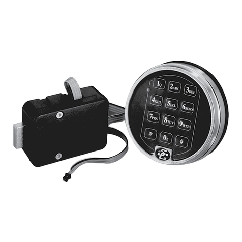
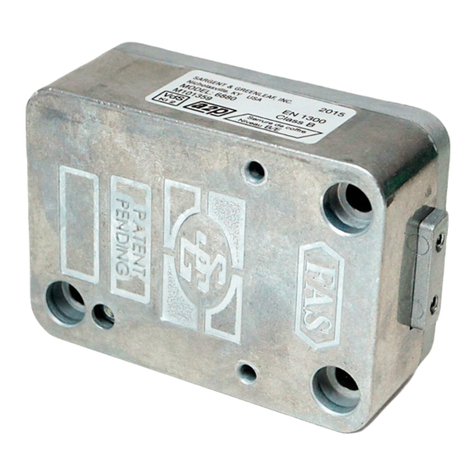
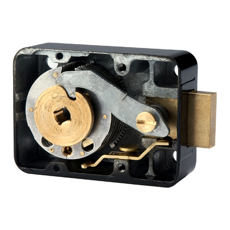
The 6124lock isnot intended for direct bolt work attachment. Before installing the
lock, operate the safe opening mechanism and verify that the installed position will
effectively secure the bolt works when the lock is locked. After installation, check that
there is clearance between the combination lock bolt and the bolt works; as pressure
onthe bolt could affect the lock’s ability to function properly.
Attaching Screws:
Use only the screws provided with the lock. They must engage the mounting plate by at
least four full threads. Do not use lock washers or thread sealing compounds.
Recommended Attaching Screw Torque:
30 to 40 inch-pounds (33.9 to 45.2 dNm) for the lock body. No more than 15 inch-pounds
(1.695 Nm) for the keypad base attaching screws.
Minimum Lock Cable (Spindle) Hole Diameter:
0.312 inch (7.9 mm)
Maximum Lock Cable (Spindle) Hole Diameter:
0.406 inch (10.3 mm)
Lock is designed to Move:
6125 LOCK-2.25lbs (10N)/ maximum intermittent load must not exceed 5.5lbs (25N)
Lock Bolt Maximum Free Movement:
0.352 inch (8.95 mm) / 0.109 inch outside the edge of the lock case
Maximum Bolt End Pressure:
lock is designed to withstand at least 225 lbs. (1000 Newtons)
Maximum Bolt Side Pressure:
Safe and container boltwork or locking cam designs must never apply more than 225
lbs. (1000 Newtons) of side pressure on the lock bolt.
Mounting Environment:
The lock body is designed to be mounted inside a secure container. The container must
be constructed to offer protection against physical attack directed at the lock. The
amount of protection is dependent on the desired level of security for the system as a
whole. Lock protection may include barrier materials, relock devices, thermal barriers,
thermal relock components, or any combination of these. Relock device attaching
screws must NOT be longer than the depth of the tapped hole provided in the lock case.
Security relevant parts of a high security lock should not be accessible to unauthorized
persons when the door ofthe secure storage unit to which itis fitted is open. A
minimum distance of 0.150 inch (3.8 mm) is recommended betweenthe end of the lock
case and the closest approach of the safe’s blocking bar or cam plate (which is normally
blocked bytheextended lock bolt). Maintaining this clearance will allow the lock to
deliver optimum performance.
Code Restrictions:
Personal data that can be related to a code holder, such as a birth date, street number,
or phone number, should not be used in creating a lock code. Avoid codes that can be
easily guessed (such as 12345678 or 11111111). The lock’s factory default codes should be
changed when the lock is put into operation by the end user.
Note:
Every installation of this product must comply with these requirements and those in the product installation instructions to qualify for the
manufacturer’s warranty and to comply with EN1300 requirements. The length of any external cabling used for this product must not exceed 3
meters in length. Use of cabling exceeding 3 meters may void product certifications.
Corporate Headquarters: One Security Drive
|
Nicholasville, Kentucky 40356
|
1-800-826-7652 . Except as otherwise noted, all trademarks in this data sheet are
trademarks of Sargent and Greenleaf in the U.S. and elsewhere. ®denotes a trademark registered with the U.S. Patent and Trademark Office and/or other Trademark
offices around the world.
3.320" (84,3mm)
2.624" (66,6mm)
