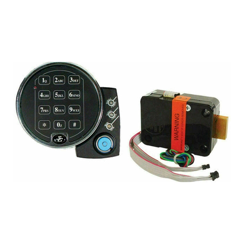
I nstallation I nstructions
Model 1OO4 Spinblocker Electronic Safe Lock SARGEl{T II{ D G REEI{ [TAT'
1t
t,
. Fiir Anweisungen auf Deutsch besuchen Sie bitte die folgende Website:
. Pour obtenir les instructions en frangais, veuillez consulter le site ci-dessous :
1 004 Spinblocker Lock Specifications
Attading Scews: Use onlyth€ soews provided with the lod.lley must engage the mounting plate byat least fourfull threads. Do not use lock
washers 0r thr€ad sealinq compounds.
Re(omm€nded Atta(hing SaewTorque: [od = 40 inch-pounds (4.5 Nm) Keypad = i5 inth-pounds {1.7 Nm)
llinimum Lo(k Cable (5pindle) Hole Diameten 0.1'12 in(h (7.9 mm)
ilarinum Lock Cable (Spindle) Hole Diamten 0.406 ind (10.3 mm)
lock is Designed to Move:0.0 lbs. {0 NeMons)
lo* Boll Maximum tree Movement: 0.352 indr (8.95 mm) 0.109 in(h outiide the edge 0fthe lo(k (ase
llarimum Eolt End Pressure: lo(k is designed t0 withstand at least 225 lbs. (1000 Newtont
llaximum 80lt Side Pressure: saf€ and (ontainer boltwork 0r l0cking (am designs must never apply more than 225 lbs. (1000 Newt0ns) 0fside
pressure on the lo(k bolt
llounting Environment: The lock body is designed t0 be mounted inside a se(ure (0ntainer.Th€ (0ntainer must be (0nstructed t0 0f1er prote(tion
against physical atta(k direded at the lo(k.The am0unt ofprot€ction is depend€nton the d€sired l€vel 0fse(urity for the system as a whole. Lod
proiection may in(lude barier mat€rials, rel0(kd€vi(es, thermal barriers, thermal relock components,0r a[y(ombinati0n 0fthese. A minimum
distan(e 0f.1 50 in(h (1.8 mm) is recomm€nded between the end ofthe lod (ase and the closest approa(h 0fthe saf€'s blocking bar ortam plate
(whid 6 normally blo(ked by the extended lod bolt). Maintaining this clearance will allow the lo(k t0 deliveroplimum performance.
lnterfe(€ with Eoltwork Ihi5 lod is not intended for dired boltwork atta(hment. 8€f0re instdlling the l0(k operat€ the safe opening merhanism
and veritthatthe innalled position will effectively se(ure the boltworks when the lork is lorked. After installation, rheck that there is tlearnace
between the (0mbination lork bolt and the boltworks as pressure 0n the bolt (ould affectthe lockS abilityto fun(tion pr0perly.
Code Restriction5: Personal data that (an be related t0 a code hold€r, surh as a birth date, street number, or phone number, should not be used
nireatingalock<ode.Avoidcodesthatonbeeasilyguesed(surhas1214560r111111).Thelocktfartorydefaultrodemustberhanqedtoa
unque, serure code when the lo(k is put into 0peration by the end user
llote: fvery installation 0fthis product must c0mply with these requirements and those in the product installation instructionst0 quali{yforthe
manufacturer's watranty and t0 (0mplywith tN1l00 requirements.
www.sargenta ndgreenleaf.com
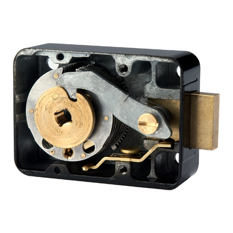
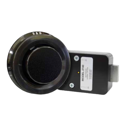
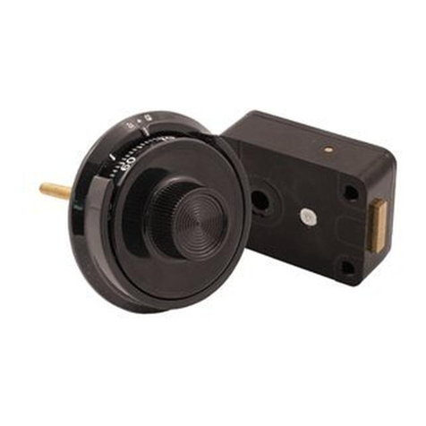
The Model 100{ spinblockcr lock is a revcrsible, non-hmded elcctronic safe lock Either side of the lock case can be mounted against the safe door to accommodate thc direction
of movement of the blocking bar or cam plate of the safe's boltrvorks. No matter which side of the case is placed against the safe's mounting plate, the lock cable needs to be
The mouting surtice should be smmth md flat, with either %-20 or \{6 mounting screw holes. The wire chmnel (spindle hole) through the safe door must be at least.3l2 inch
(7.9 mm) in dimeter. Connect the cable to the lock, NOTE that this is a latching connector and cannot be removed from the lock without actuating the latch releasc. Insert the
lock cable through the spindle hole md gently pull it from the front of the safe as you place the lock body against the mouting surface.
.\her mxing sure the cable is protected within the lock's recessed channei and not crimped or stresed at any point, attach the lock bodr. to rhe mounting surface using the four
screws provided. Tighten the four mounting screws to 40 inch-pounds (4.5 Nm).
Make sure there is a minimum clearance of0.l50 inch (3.8 mm) between the end ofthe lock case and the blocking bar ofthe safe! boltworks. Check that there is clearance on all
If additional clearance is required, remove material from the safe boltworks, not the lock.
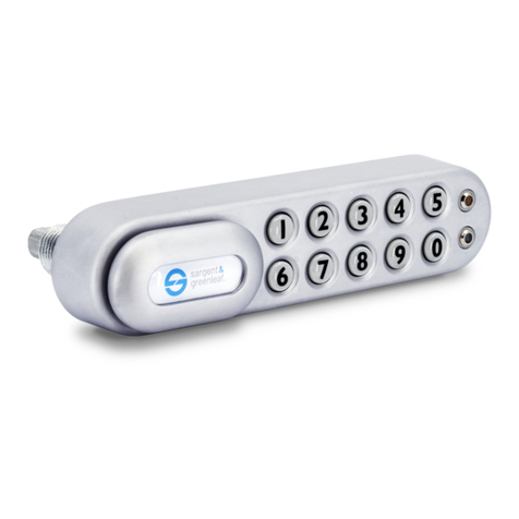
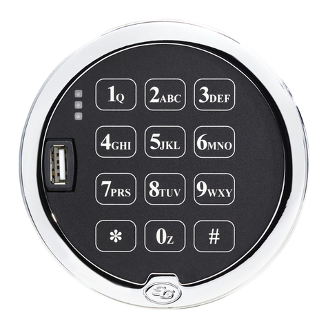
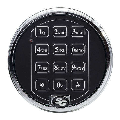
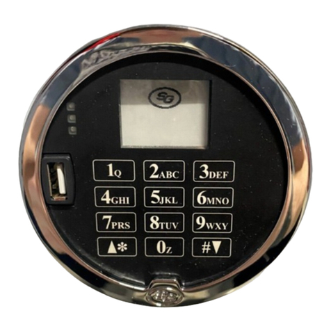
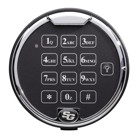
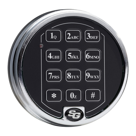
Ffe{ Keypad Installation
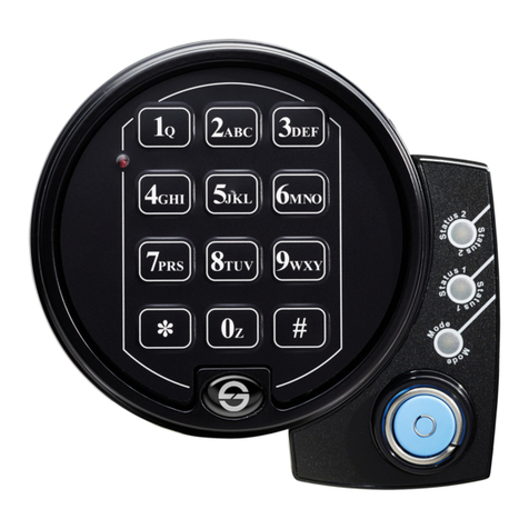
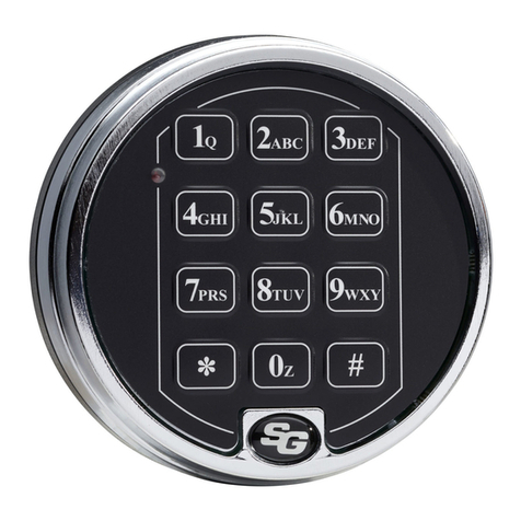
(a) Position the kelpad houing on the safe door so that the battery door is at the bottom and attach using (2) zE 32 or MO.7 screw and (2)
T-shaped spacers. (Figure la)
(b) Pass the loose end of the lock cable through the spindle hole and kelpad housing and plug the lock cable into the receptacle in the back of
the keypad electronic rsembll'.
(c) Coil the excess lock cable into the space provided in the back of the kevpad,
(d) Guide the 9V battery cable through the slot in the kelpad housing. THE B.{TTER)' CONNECTOR MUST BE ACCESSABLE FROM
THE BATTERY DOOR BEFORE SNAPPING THE KEYPAD TOGETHER OR THE KEYPAD \{ILL BE INOPERABLE. Snap the kelpad
electronic assembly to tie housing until evenly seated. (Figua lb, lc)
Quick Mount Keypad Installation (refer to document 630-876 for more information)
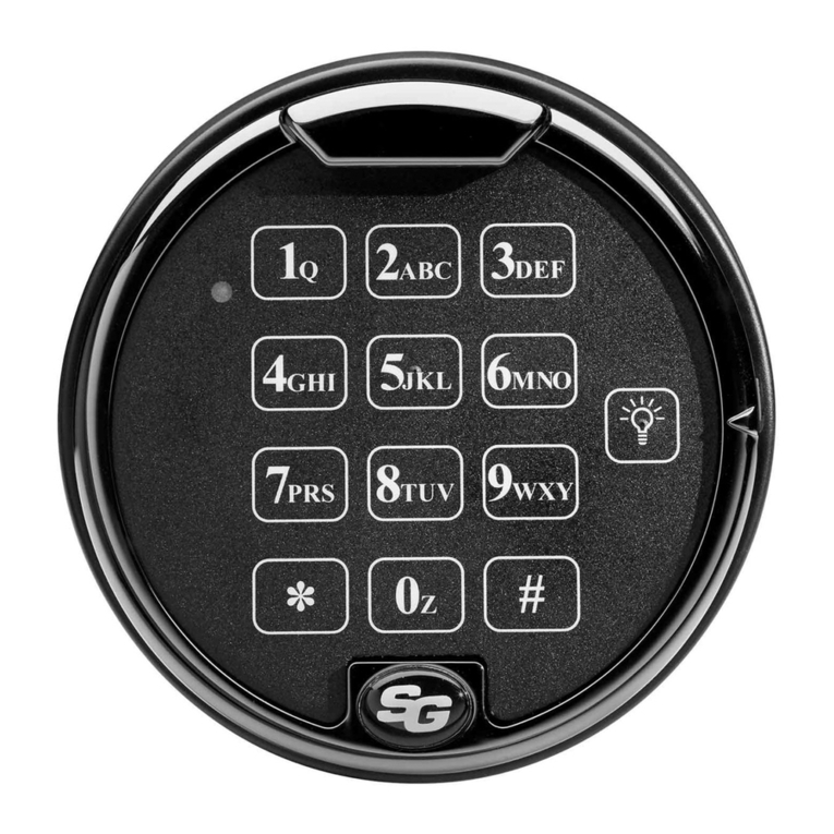
(a) Place metal collars over the k€pad mounting screws and install screws into mounting holes in safe door. (Figure 2a)
(b) Plug lock cable coming through the spindle hole into the receptacle in the back ofthe keypad.
(c) Coil the excess lock cable into the space provided in the back of the keypad.
(d) Angle the keypad at m - I I oilck position oler the mountirg screws. Push t'la: against the sal-e door.
Pull do*'n in the direction irdiated bv the arrow to a positive stop. The novemenl will be ls rhm ': inch. (Figure 2b)
(e) Turn ke12ad clockwise a fe*'degrees util it comes to a stop. Nub€r colmns should now be stnight u up md do*n. (Figure 2b)
Sliding door at bottom of kqpad prol'ides battery access. Slide door to left to open. Snap 9-volt battery onto connector md place
battery inside kelpad. (Figure 2c) Note Battery will only install when polarity is matched 'sith connector. Ensure alt wires are inside
kclpad and slide door to right until fullv ckrsed. Battery removal is reverse of installation. For initial installation, install battery and test
the lock and kelpad operation at least 3 times before closing the safe door, using the factorv combination I 2 3.1 5 6'.
NOTE: The lock combination must be chmged tiom the lactory setting before being put into seruice.
MAKE SURE YOUR LOCK IS FULLY OPER-{T]ONAL BEFORE CLOSING THE SAFE DOOR FOR THE FIRST TIMF,.
Figure la
Sargent & Greenleaf, lnc.
P0 Box 930
Nicholasville, KY 40340-0930 USA
Phone: (800)-826 -1652 Fax: (800)-634-.4843
Phone, (859)-885-9411 Fax, (859)-887-2057
Copyright@ 2017 Sargent & Greenleaf, lnc.
lo
Figure 1c
Figure 2c
Sargent & Greenleaf S.A.
9, Chemin du Croset
1024 Ecublens, Switzerland
Phone: +41-21 694 34 00
Fax' +41-21 694 34 09
Document 630-905
Revised 02/10/2017
Figure 2b
!
t)
page 1
