SATO M-8400RVe Series User manual

SATO EUROPE
M8400RVe
Operation Manual
SATO Europe
Im Hülsenfeld 13
40721 Hilden
Germany
Tel.:+49 (0)2103 9592-0
Fax.:+49 (0)2103 55322
Issued November 2000

This page is intentionally left blank.

Warning
It is essential that the safety and operating procedures contained
within this manual be brought to the attention of, and are used by,
all personnel likely to operate this printer/product.
This printer/product must only be used for the purpose for which it
was designed.
This is a Class A product. In a domestic environment this product
may cause radio interference in which case the user may be
required to take adequate measures.
Electrostatic discharges on the connector pins and on the memory
card may damage the printer.
In the case of fire, water must not be used on the product to extin-
guish the fire, and the appropriate type of fire extinguisher should
be readily available.
No modifications, either mechanical or electrical, should be made
to this printer/product or accessory without the written consent of
SATO Europe GmbH. Any modifications made without this consent
may invalidate guarantee claims.
Other manuals relating to this printer include additional information
relating to other aspects of the safe operation of the printer, and are
available from your SATO supplier.
All consumable waste, such as the label backing paper and used
carbon ribbon must be disposed of carefully, and in a manner that
will cause the minimum of environmental pollution.
Should you have any doubts regarding the setting, operating or any
safety aspects of this printer/product, please contact your SATO
supplier.
SATO Europe GmbH makes no guarantee that all the features
described in this manual are available in all models, and, due to
SATO’s policy of continuous development and improvement, spec-
ifications are liable to change, without notice.

Consumables
Always use SATO carbon ribbons or equivalent. The use of incor-
rect materials may cause malfunctions of the printer and void the
warranty.
Conventions
Text that appears bold italic and all in capitals such as LABEL
refers to a key or an LED on the operation panel.
Text that appears enclosed in brackets such as <ESC> refers to an
Escape sequence of a data string.
Text that appears bold italic such as On-Line refers to a function or
to a result.
Text that appears in bold such as VR1 refers to electrical compo-
nents like pins, resistors connectors and so on.
Warranty and Copyright
SATO Europe GmbH makes no guarantee of any kind with regard
to this material, including, but not limited to, the implied guaranties
of merchantability and fitness for a particular purpose.
SATO Europe GmbH shall not be liable for errors contained herein
or for any incidental consequential damages in connection with the
furnishing, performance, or use of this material.
This document contains proprietary information which is protected
by copyright.
All rights are reserved.
No part of this document may be reproduced or issued to third par-
ties in any form whatsoever without the express permission of
SATO Europe GmbH.
The information in this document is subject to change without
notice.
© Copyright 2000 SATO Europe GmbH

i
Contents
1. Overview and Specifications .......................................................... 1
1.1 Overview ............................................................................. 1
1.2 Physical Characteristics ..................................................... 2
1.3 Components ....................................................................... 3
1.4 Ribbon ................................................................................ 5
1.5 Installation Considerations ................................................. 5
1.6 Interface Connections (Rear Panel) .................................. 5
1.7 Switches and Sensors ........................................................ 6
1.8 Operator Panel/Displays ..................................................... 8
1.9 Specifications .................................................................... 10
2. Printer Configuration .................................................................... 13
2.1 DIP Switch Settings .......................................................... 13
2.1.1 RS232 Transmit/Receive Setting ........................... 14
Selecting Protocol Control Codes .......................... 17
2.1.2 External Connector PIN Assignments .................... 21
2.1.3 External Output Signal Types ................................. 22
2.2 Default Settings ................................................................ 23
2.3 Printer Adjustments .......................................................... 24
2.3.1 Normal Mode .......................................................... 24
2.3.2 User Mode .............................................................. 24
2.3.3 Print Darkness Setting ............................................ 25
2.3.4 Print Speed Adjustment .......................................... 25
2.3.5 Pitch Offset and Direction ....................................... 26
2.3.6 Cancel print Job ..................................................... 27
2.3.7 Advanced Settings ................................................. 27
3. Connections ................................................................................. 29
3.1 Bi-directional parallel interface (standard) ........................ 29
3.2 Optional interface (RS-232C) ........................................... 30
3.3 Optional Interface (USB) .................................................. 31
3.4 Optional Interface (LAN) ................................................... 31
4. Media Loading ............................................................................. 33
4.1 Loading the Ribbon .......................................................... 33
4.2 Loading Labels or Tags .................................................... 35
5. Cleaning and Maintenance .......................................................... 39

ii
5.1 Introduction ....................................................................... 39
5.2 Adjusting the Print Quality ................................................ 40
5.3 Cleaning the Print Head, Platen and Rollers .................... 42
6. Troubleshooting ........................................................................... 45
6.1 Overview ........................................................................... 45
6.2 Initial Checklist .................................................................. 45
6.3 Error Signals ..................................................................... 46
6.4 Troubleshooting Tables ..................................................... 47
Appendix A Advanced Settings ......................................................... 51
Appendix B Declaration of Conformity .............................................. 55

Operation Manual 1. Overview and Specification
M8400RVe1
1. Overview and Specifications
1.1 Overview
The SATO M-8400RVePrinter Operation Manual provides informa-
tion for installing and maintaining the M-8400RVeprinter. Step-by-
step maintenance instructions are included in this manual with typ-
ical problems and solutions. It is recommended that you become
familiar with each section in this manual before installing and main-
taining the printer.
This manual is divided into the following seven sections:
• Section 1 - Overview and Specifications
• Section 2 - Configuration
• Section 3 - Connections
• Section 4 - Media Loading
• Section 5 - Cleaning and Maintenance
• Section 6 - Troubleshooting

2 M8400RVe
1. Overview and Specification Operation Manual
1.2 Physical Characteristics
DIMENSIONS
Width 280 mm
Depth 438 mm
Height 341 mm
Weight 18 Kg
POWER REQUIREMENTS
Voltage 220 V (+/- 10 %)
50/60 Hz (+/- 1%)
Power Consumption 50 Watts Idle
300 Watts Operating
Width
Depth
Height

Operation Manual 1. Overview and Specification
M8400RVe3
1.3 Components
OPERATOR
PANEL
RIBBON UNWIND
SUPPLY
RIBBON REWIND
SPINDLE
PRINT HEAD
ASSEMBLY
PLATEN ROLLER
DIP SWITCH
CONFIGURATION
TABLE AND MEDIA
LOADING DIAGRAM
MEDIA HOLDER
SENSORS AND SWITCHES
Refer to Section 1.7
LCD DISPLAY
POWER ON/OFF
SWITCH
LABEL SENSOR
POSITIONING ADJUSTMENT
TOP ACCESS
DOOR
SIDE ACCESS
DOOR
LABEL ROLL
RETAINER
HEAD LATCH

4 M8400RVe
1. Overview and Specification Operation Manual
TEAR OFF
LABEL COVER
MAIN PC BOARD
POWER
SUPPLY UNIT
LCD BOARD
LED BOARD
(ON BACKSIDE
OF PANEL)
STEPPER MOTOR
SHAFT
TIMING BELTS
Operation Manual 1. Overview and Specification
M8400RVe5
1.4 Ribbon
Use only SATO thermal transfer ribbons which were formulated
expressly for use in all SATO printers. Use of other than approved
ribbons may result in unsatisfactory print quality and/or damage to
the print head and may void your warranty.
1.5 Installation Considerations
Printer operation can be affected by the printer environment. The
location of the printer should be free from dust, humidity, and sud-
den vibrations. To obtain optimum results from the printer, avoid
locations influenced by:
• Direct or bright sunlight since bright light will make the label sen-
sor less responsive and may cause the label to be sensed incor-
rectly.
• Warm temperatures which can cause electrical problems within
the printer.
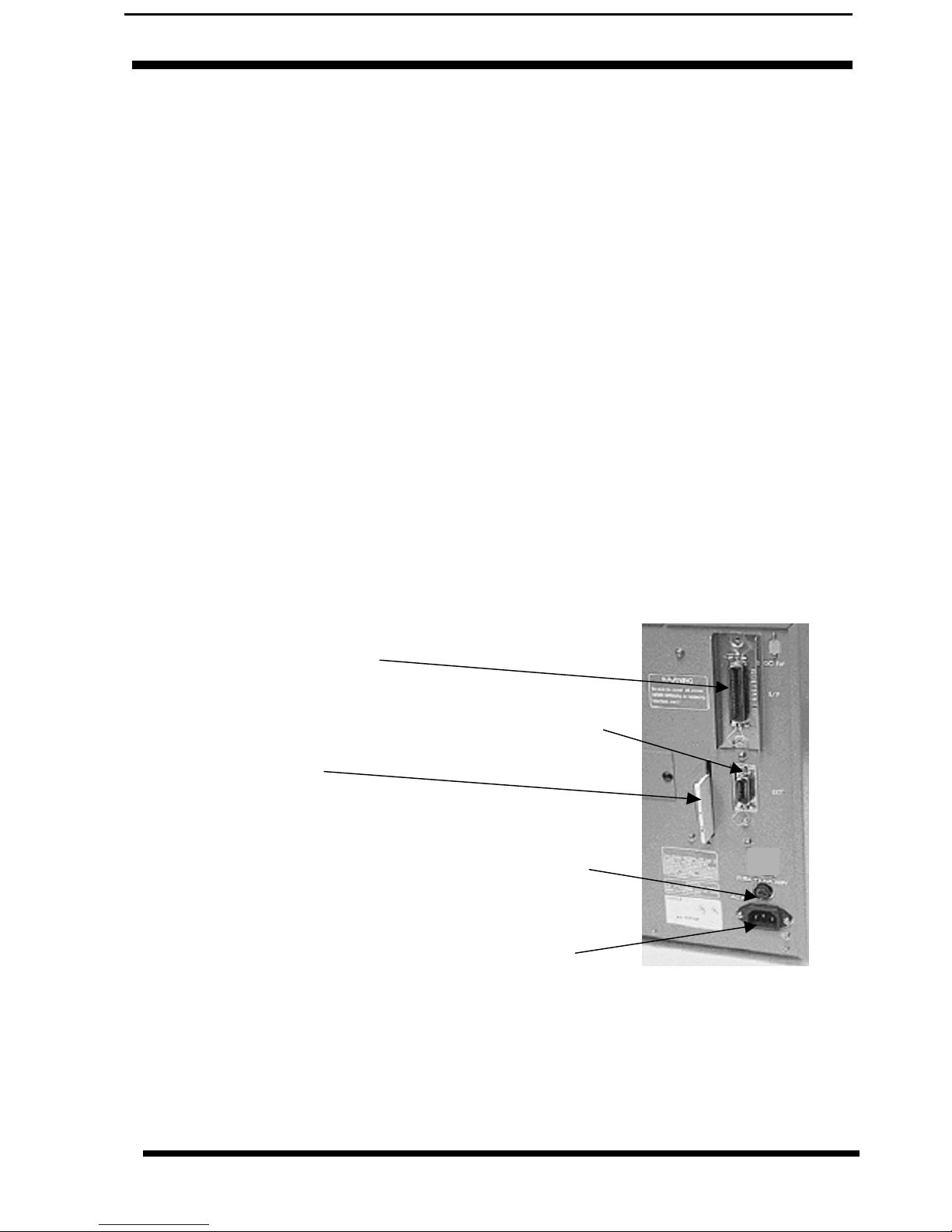
1.6 Interface Connections (Rear Panel)
EXT. PORT CONNECTOR:
External signal connector.
AC FUSE: To protect the machine
from abnormal power input.
Type 3A/250V
AC INPUT CONNECTOR:
Connect to 220V 50/60 Hz.
with cable provided.
MODULAR INTERFACE:
MEMORY CARD:

6 M8400RVe
1. Overview and Specification Operation Manual
1.7 Switches and Sensors
HEAD LATCH LEVER: When the
print head is opened, a micro switch is
activated and the printer will stop
printing. Error message will be
displayed on the LCD operator panel.
RIBBON SENSOR: The sensor will react
to the ribbon unwind when approximately
45 feet of ribbon remains. This sensor is a
motion detector that signals the printer
when the ribbon supply is turning. This
sensor is used for both the ribbon end and
ribbon near end sensing. When error is
displayed: Ribbon out, not turning.

Operation Manual 1. Overview and Specification
M8400RVe7
MICRO SWITCH (Head Open Switch)
MEDIA HOLD DOWN:
Open by lifting up on the release
tab underneath the green tab
marked “PUSH”.
Close by pushing down on the
same green tab.
LABEL OUT SENSOR: Micro switch is
activated when media stock is out or when the
Media Hold Down is in the up position. All
printer operations stop and an error message is
displayed on the LCD.
LABEL SENSOR UNIT: Both the “I”-
Mark (reflective), and Gap (transmissive)
sensors can be adjusted over a limited
range. They are both located in the label
sensor unit. The assembly can be
adjusted by turning the sensor adjust
knob located underneath the label
transport assembly. The gap sensor can
be adjusted from a minimum of 15 mm to
a maximum of 63 mm, and the “I”- Mark”
from a minimum of 7 mm to a maximum
of 52 mm from the fixed position, inside
label guide. The range of sensor
adjustment can be increased to allow the
Gap sensor to be positioned as close as
3mm from the inside label edge.
8 M8400RVe
1. Overview and Specification Operation Manual
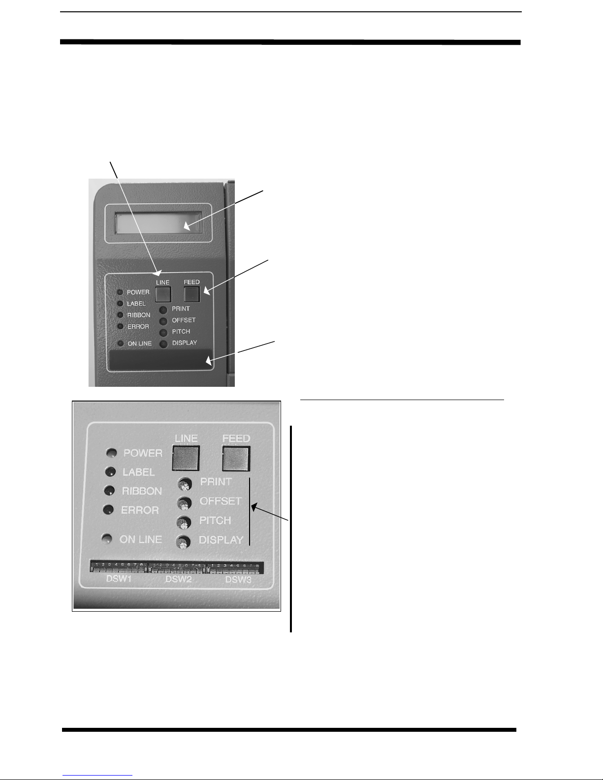
1.8 Operator Panel/Displays
LINE Key: Momentary switch. Pressing this key toggles the printer
between the on-line and off-line mode. When the printer is on-line, it is
ready to receive data from the host. This key acts as a pause during a
print job by taking the printer off-line.
FINE TUNING - USE SOFTWARE FIRST
PRINT POTENTIOMETER: To adjust
print darkness (fine adjustment).
OFFSET POTENTIOMETER: To adjust
back/forward feed for dispenser/cutter/tear
- bar position (+/- 3.75mm).
PITCH POTENTIOMETER: Adjusts home
position of the label(+/- 3.75mm). Affects
stop position of label feed, print position,
and dispense position.
DISPLAY POTENTIOMETER: Used to
adjust the lighting intensity (contrast) of the
Display.
LCD SCREEN:2 Line x 16 Character LCD
display. Used for setting operational parameters
of the printer and displaying error conditions.
FEED Key: Momentary switch.
Pressing this key feeds one blank label
through the printer when it is off-line.
When the printer is on-line, another copy
of the last label will be printed.
DIP SWITCH COVER
Operation Manual 1. Overview and Specification
M8400RVe9
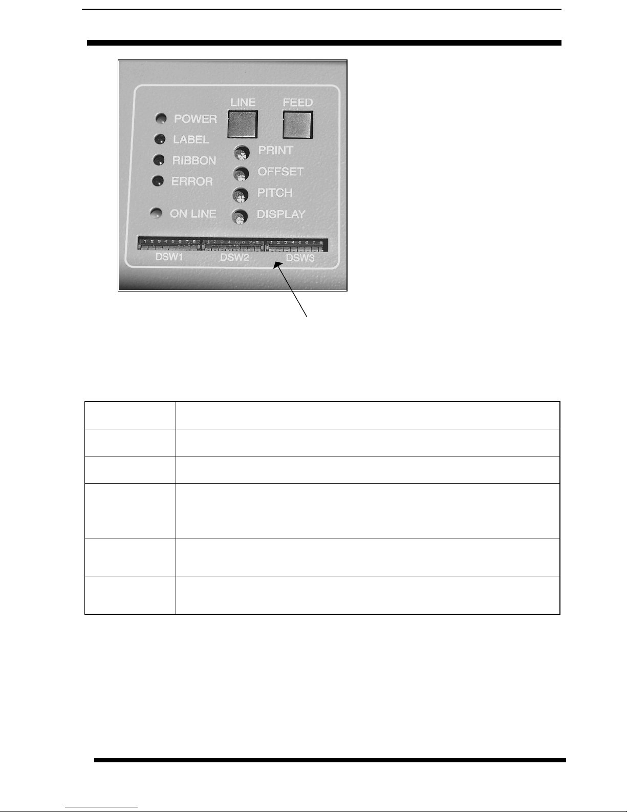
LED’S: - STATUS INDICATORS
POWER LED, illuminated when the power is on.
LABEL LED, illuminated when label supply is out.
RIBBON LED, illuminated when ribbon motion sensor does not detect
any ribbon motion (ribbon out), or the LED blinks when ribbon
is near end.
ERROR LED, illuminated when there is a system fault such as an open
print head.
ON LINE LED, illuminated when printer is ready to receive data. Turn
ON/OFF by toggling the LINE key.
DSW 2 & 3: DIP Switches used to set
operational parameters of printer. Refer
to Section 2 for settings.

10 M8400RVe
1. Overview and Specification Operation Manual
1.9 Specifications
Print Type Direct Thermal, Thermal Transfer
Resolution 8 dot/mm (203 dpi) 0,125 mm/dot
Speed User selectable from 50 mm/sec to 250 mm/sec
Darkness 5 steps; selectable by printer driver (<ESC> codes) or via display
Print Area Pitch: 178mm Width: 104mm Standard
356mm 104mm <AX>
1249mm 104mm Option <EX>
Media
Label Sizes Pitch: 6–356 mm; optional max:1249 mm
17–356 mm; optional max:1249 mm
Width: 22–128 mm Standard
22–128mm Cutter or Dispenser
Label Roll I.D. 38mm (1,5”) or 76 mm (3”); O.D. 220mm (8,6”);
Thickness 0,1-0,18 mm
Media Types Die-Cut Label, Continuous Material, Tag Material, Roll Type - Face-In, Fan-Fold
Type.
Carbon
Ribbon
Width: 111 mm max. Length: 450 metres, Thickness: 4,5 µ,
Type: Black and Colour, Back Coated
Barcodes UPC A/E, EAN 8 & 13, Code 39, Code 128, UCC/EAN 128, Interleaved 2 of 5,
Industrial 2 of 5, Matrix 2 of 5, NM-7, MSI, Bookland, Postnet.
Barcode
Ratio
1:2, 1:3, 2:5
Barcode
Sizes
Height: 4 dots to 600 dots; width – user definable
Rotational
Capacity
90° steps
2-D Codes Data Matrix, Maxicode, PDF 417, QR-Code
Fonts U, S, M, WB; WL; XU; XS; XM; XB; XL; OCR-A/B; Outline Font (50-999)
Rasterizer Font Triumvirate®& Times®(08 – 99 points or 16 – 999 dots)
Label Sens-
ing
Reflective Sensor (I-mark) bottom reading, movable
See-through Sensor (Gap), movable
CPU 32 bit SH3 RISC Processor/ 133MHz
Memory
Capacity
Standard Memory:
Optional Memory Expan-
sion:
16MB SDRAM; 2,9MB Input Buffer; 2MB Flash Mem-
ory
I n t e r n a l - 4 M B F l a s h M e m o r y S I M M C a r d
External - up to 4MB S-RAM Card or up to 16MB
Flash Card
Interfaces ECP Parallel (IEEE 1284),Centronics Parallel,RS232C Standard (2400 – 19.200
Baud), RS232C Highspeed (9600 – 57.600 Baud), USB (12Mbit/s),LAN (TCP/IP
protocol 10/100 Base T), Twinax/Coax,RS422/485.

Operation Manual 1. Overview and Specification
M8400RVe11
Front Panel Operation Switches:
Setting Switches:
LED:
LCD:
Online Key, Feed Key
2 x 8 Dip-Switches
Power, Label, Ribbon, Error, Online
Menu Controlled Printer Configuration and Error Messages
Supported Languages:
English (default), German, French, Spanish, Italian, Portu-
guese
Dimensions Height: 321 mm Width: 271 mm Depth: 430 mm
Weight 19 kg (standard)
Power 110 - 240V +/- 10%, 50/60 Hz, 130W
Environmen-
tal
Operating: +5 ~ +40°C, humidity 15 ~ 85% RH non-condensing
Storage: -20 ~ +55°C, non-condensing
Approvals C E, TÜV-GS, UL, CSA,
Options Rotary Cutter, Dispenser, External Label Rewinder R400, Memory Expansion,
Keyboard, Real Time Clock

12 M8400RVe
1. Overview and Specification Operation Manual
This page is intentionally left blank.

Operation Manual 2. Configuration
M8400RVe13
2. Printer Configuration
2.1 DIP Switch Settings
Two DIP switches DSW2 and DSW3 are located on the Operator
Panel at the front and a DSW1 switch is located on an optional
RS232 serial interface board.
These switches can be used to set:
• RS232C transmit/receive parameters
• Thermal transfer or direct thermal mode
• Label sensor enable/disable
• Head check mode
• Hex dump mode
• Receive buffer size
• Operation mode
To set the switches, first power the unit Off, then position the DIP
switches. After placing the switches in the desired positions, power
the printer back on. The switch settings are read by the printer
electronics during the power up sequence. They will not become
effective until the power is cycled.
DIP Switch Panel Layout for DSW1
Located on RS232 Interface Board

14 M8400RVe
2. Configuration Operation Manual
2.1.1 RS232 Transmit/Receive Setting
Data Bit Selection (DSW1-1)
This switch sets the printer to receive either 7 or 8 bit data bits for
each byte transmitted.
Parity Selection (DS1-2, DS1-3)
These switches select the type of parity used for error detection.
Stop Bit Selection (DS1-4)
Selects the number of stop bits to end each byte.
Baud Rate Selection (DS1-5, DS1-6)
Selects the data rate(bps) for the RS232 port.
* Factory Default
DSW1-1 SETTING
*OFF 8 Data Bits
ON 7 Data Bits
12 345678
ON
OFF
DSW1
12 345678
ON
OFF
DSW1
DSW1-2 SETTING SETTING
*OFF *OFF No Parity
OFF ON Even
ON OFF Odd
ON ON Unused
DSW1-4 SETTING
*OFF 1 Stop Bit
ON 2 Stop Bits 12 345678
ON
OFF
DSW1
DSW1-5 DSW1-6 SETTING
*OFF *OFF 9600
OFF ON 19200
ON OFF 38400
ON ON 57600
12 345678
ON
OFF
DSW1
Other manuals for M-8400RVe Series
3
Table of contents
Other SATO Barcode Reader manuals

SATO
SATO CG412DT User manual

SATO
SATO GL408e User manual

SATO
SATO ARGOX AS-9400BT User manual

SATO
SATO S8400 User manual

SATO
SATO Argox D4 Series User manual

SATO
SATO iGT400 Series User manual

SATO
SATO MB 200i User manual

SATO
SATO DR308e User manual

SATO
SATO Argox AR-3201 User manual

SATO
SATO MB 200i User manual


