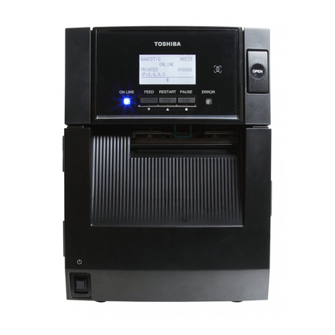
SATO MB 200i User manual

1
1234567890123456789012345678901
1
23456789012345678901234567890
1
1
23456789012345678901234567890
1
1
23456789012345678901234567890
1
1
23456789012345678901234567890
1
1
23456789012345678901234567890
1
1
23456789012345678901234567890
1
1
23456789012345678901234567890
1
1
23456789012345678901234567890
1
1
23456789012345678901234567890
1
1
23456789012345678901234567890
1
1
23456789012345678901234567890
1
1
23456789012345678901234567890
1
1
23456789012345678901234567890
1
1
23456789012345678901234567890
1
1
23456789012345678901234567890
1
1
23456789012345678901234567890
1
1
23456789012345678901234567890
1
1
23456789012345678901234567890
1
1
23456789012345678901234567890
1
1
23456789012345678901234567890
1
1
23456789012345678901234567890
1
1
23456789012345678901234567890
1
1
23456789012345678901234567890
1
1
23456789012345678901234567890
1
1
23456789012345678901234567890
1
1
23456789012345678901234567890
1
1
23456789012345678901234567890
1
1
23456789012345678901234567890
1
1
23456789012345678901234567890
1
1
23456789012345678901234567890
1
1
23456789012345678901234567890
1
1
23456789012345678901234567890
1
1
23456789012345678901234567890
1
1
23456789012345678901234567890
1
1
23456789012345678901234567890
1
1
23456789012345678901234567890
1
1
23456789012345678901234567890
1
1
23456789012345678901234567890
1
1234567890123456789012345678901
Barcode Printer
Quick Guide

32
Introduction
This manual is intended to help you become familiar with the
basic operation of Petit lapin the barcode printer in a short
time.
Please read this manual carefully to make full use of the
functions of Petit lapin.
Notes
1. Reproduction of all or part of this manual is prohibited
without permission of the copyright owner.
2. The information in this manual is subject to change
without notice.
3. If you find any ambiguous or erroneous information in
this manual, please contact your nearest dealer or
service center.
Warning
This is a Class B product based on the standard of the
Voluntary Control Council for Interference by Information
Technology Equipment (VCCI). If this equipment is used in a
domestic environment, radio disturbance may arise. When
such trouble occurs, the user may be required to take
corrective actions.
First Edition October 1, 2004
© 2004 Sato Corporation
Notes on Radio Wave
This product has been approved of adaptability in the
technological standard based on Radio Law. Therefore, use
of this product does not require a license for radio station.
This product is limited for use in Japan only.
The following behavior may result in judicial punishment.
• Disassembling/modifying this product
•Removing the certificate label (serial number seal)
attached on this product
Use of this product in the following place may shorten the
communication distance or disable communication.
Near microwave oven, place where static electricity or radio
failure is caused, or near wireless LAN equipment.
“Bluetooth” is a trademark of
Bluetooth SIG, Inc., USA. We use
the mark with a license by the said
company.
Before using wireless LAN interface, be sure to make all the
settings related to the security of wireless LAN equipment in
accordance with the manual supplied with the equipment.
For Customers Using the Bluetooth or Wireless
Communication Models

54
Table of Contents
1. Safety Precautions ....................................... 6
Markings and Symbols ............................ 6
Precautions in Use ................................ 13
2. Unpacking .................................................. 14
3. Parts Name ................................................ 15
Name and Function of Controls ................. 17
4. Before Starting ........................................... 18
Charging the Battery Pack .................... 18
Installing and removing the Battery Pack .
21
Using AC Adapter .................................. 23
Setting Labels ........................................ 24
• Continuous mode ............................ 24
• Dispense mode ............................... 26
5. Turning Printer On ..................................... 29
6. Test Printing ............................................... 30
7. Using RS-232C Interface ........................... 31
8. Using IrDA Interface ................................... 32
9. Using Bluetooth Interface or Wireless LAN
Interface .................................................. 33
10. Printing ....................................................... 34
11. When in Trouble ......................................... 36
12. Daily Maintenance ..................................... 39
Preparation
Operation
First Aid
Routine
Maintenance
Reference
13. Reference .................................................. 41
Options .................................................. 41
Operation Mode ..................................... 47
Basic Specifications of Petit lapin .......... 56
Before Asking for a Repair .................... 58
After-sale Services ................................ 59

Safety Precautions
1
7
Safety Precautions
1
6
Symbol examples
The triangle ( ) indicates something you should
take absolute care with. The cautions are indicated
concretely within the symbol. The symbol on the left
indicates a risk of electric shock.
A circle with a diagonal line ( ) indicates something
you should not do. The symbol on the left indicates
that you should not try to take the unit apart.
A black circle with a picture inside ( )indicates
something you need to do. The symbol on the left
indicates that you should unplug the unit from the
wall outlet.
Warning
1. Safety Precautions
In this section, safety precautions about printer operation
are explained to ensure proper care and usage. Make sure
to read these carefully before using your printer.
Markings and Symbols
The following symbols or markings are used in this manual
and on the printer so that you can properly use the printer,
and to prevent any damage to property, harm or injury to
yourself and others. Make sure to read their explanations
carefully to familiarize yourself with their meanings.
This symbol indicates information
that, if ignored or applied incorrectly,
creates the danger of death or
serious personal injury.
This symbol indicates information
that, if ignored or applied incorrectly,
creates the possibility of personal
injury or property damage.
Caution

Safety Precautions
1
9
Safety Precautions
1
8
Abnormal Conditions
Continued use of the printer while it is emitting smoke
or strange odors creates the danger of fire or electric
shock. Immediately turn off the power and contact
your nearest dealer or service center. Do not try to
service the printer by yourself.
Disassembly
Never try to take the unit apart or modify it in any
way. Doing so creates the danger of fire or electric
shock. Contact your nearest dealer or service center
for repair.
Battery Pack
• Never try to take apart the battery pack or modify it
in any way such as with a solder iron.
•Never expose the battery to direct flame, throw it
into fire, or take any actions that may lead to
shorting.
•When charging the battery pack, make sure to use
the printer or the specified battery charger.
Warning
Warning
Liquid
Do not place any container with water or chemicals,
such as flower vase or cup, as well as small metallic
objects, near the printer. If any of these should fall
into the printer, immediately turn off the power and
contact your nearest dealer or service center.
Continued use creates a damage of fire or electric
shock.
Foreign Matter
Do not drop or insert metallic or flammable objects
into the openings on the printer (such as outlets for
cables). If any of these should fall into the printer,
immediately turn off the power and contact your
nearest dealer or service center. Continued use
creates a danger of fire or electric shock.
Dropping and Damage
Should the printer ever fall or otherwise become
damaged, immediately turn off the power and contact
your nearest dealer or service center. Continued use
creates a danger of fire or electric shock.

Safety Precautions
1
11
Safety Precautions
1
10
Location
Do not locate the printer in the area subjected to high
humidity or dew. If dew forms inside the printer,
immediately turn off the printer and do not use it until
it has been dried up. Continued use creates the
danger of electric shock or the printer damage.
Power
Do not use wet hands to operate the power switch,
replace the battery pack or unplug the AC adapter or
battery charger. Doing so creates the danger of
electric shock.
Thermal Head and Stepping Motor
• The thermal head gets very hot after printing. Take
care when replacing paper or cleaning the printer
just after printing to avoid burn.
•Touching the end of the thermal head with bare
hands may cause injury. Take care when replacing
paper or cleaning the printer to avoid injury.
•Do not try to replace the thermal head by yourself.
Doing so creates the danger of injury, burn, or
electric shock.
Easy Cutter
This part contains a blade. Take care to avoid cutting
your hands.
Caution
AC Adapter/Battery Charger (Option)
•Use only the specified voltage. Using a different
voltage may create the danger of fire or electric
shock.
•Use only the specified battery charger. Using a
different battery charger may create the danger of
fire or electric shock.
• Never use the battery charger with any other
battery pack except for the specified one. Doing so
can rupture the battery, cause leakage, fire or
electric shock.
•Never cut, damage or modify the power cord. Also,
never place heavy objects on the power cord or
heat or pull the power cord. Doing so may damage
the cord and create the danger or fire or electric
shock.
•Should the power cord ever become seriously
damaged (internal wiring exposed or shorted),
contact your nearest dealer or service center for
repair. Continued use of such a cord creates the
danger of fire or electric shock.
•Never modify, excessively bend, twist, or pull the
power cord. Doing so creates the danger of fire or
electric shock.
Warning

Safety Precautions
1
13
Safety Precautions
1
12
Precautions in Use
Do not place the printer in a hot or cold place.
The operation temperature range is -15°C to 50°C. Do not
place the printer in an area with high humidity or at the
temperature outside the specified range.
Do not drop or give shock to the printer.
The printer is given a protection against vibration possibly
caused during normal transportation. However, do not apply
extreme vibration or shock by dropping to the printer.
Do not disassemble or modify the printer.
The printer has high-precision components inside requiring
fine adjustment. Do not disassemble the printer.
Connect the specified cables to the external
input terminals.
Special cables are required to connect to the external
equipment through the external input terminals. Contact
your nearest dealer or service center if necessary.
Use a specified option.
Do not use a device not specified as option. Otherwise a
fault may occur.
Use the specified paper.
Use the specified paper. Otherwise, broken head or faulty
printing may occur.
Replacing the Battery Pack
• Use only the specified battery pack.
•When replacing the battery pack, make sure to
install the pack with the correct direction. Incorrectly
replacing the battery create the danger of injury or
damage to surrounding areas.
•Replacing a small-size rechargeable battery
(Lithium ion battery) Apply insulation treatment for
the old battery pack by sealing the contact with tape
or the like and ask our sales representative or
service center for the measure to be taken for
effective use of scarce resource. Do not place the
battery pack together with other batteries such as
dry batteries.
Leaving the printer unused for a long time
If you have no plan to use the print for a long time,
remove the battery pack from the printer and unplug
the AC adapter from the wall outlet.
Maintenance and Cleaning
For safe maintenance or cleaning of the printer, make
sure to remove the battery pack and the AC adapter
from the printer.
Caution

Unpacking
2
14
Parts Name
3
15
3. Parts Name
Open cover
Cover open/close lever
Dispenser unit
Belt clip
Easy cutter
Battery cover
Cover for DC input jack
RS-232C
cover
Label guide adjust
dial cover
2. Unpacking
After unpacking, make sure that all the printer components
are present. If any component or part is missing, contact
your nearest dealer or service center.
Warranty card
Quick guide
Printer
Battery pack
*Belt holder has already installed on the printer when shipping (see Page
42).
Shape of cushioning material (protecting bad, etc. for supporting printer)
may partly differ by the lot.
Belt hook Shoulder belt
Label ejection

Parts Name
3
17
Parts Name
3
16
Name and Function of Controls
RS-232C Interface: Connects to
PC or handy terminal.
RS-232C cover: Cover for RS-
232C connector.
Open cover: Opened for setting
labels.
Cover Open/Close lever: Used to
open or close the cover.
Easy cutter: Cuts printed labels.
IrDA filter: Contains IrDA sensor
and emitter.
DIP switch: Sets the operation
mode of the printer. (See page
53.)
Dispenser unit: Moved to select
Dispense mode.
POWER key: Turns on/off the
printer.
Battery cover: Cover for special
battery pack.
Battery indicator (LED): Indicates
the remaining amount of
battery of the printer.
Belt clip: Used when hanging the
printer on your belt.
*Do not hang the printer on to
anything but a belt.
Label guide: Set to meet the size
of the label used.
Label guide adjust dial: Adjusts
the label guide to the width of
the label used.
Label guide adjust dial cover:
Cover for label guide adjust
dial.
Label ejection: Ejects the printed
label.
Label width scale: Indicates the
width of label used.
DC input jack: Connects to AC
adapter.
Cover for DC input jack: Cover
for DC input terminal and DIP
switch.
FEED key: Press to feed label.
PRINT key: Sets the printer online
or offline.
STATUS (LED): Indicates the
status of the printer.
(See pages 36, 37, and 48 to
52.)
234
4
D
1
30
40
50
58
30
40
50
58
*1Operation panel with LCD is built in the wireless LAN interface model
only (for manufacture option). For other option information, see
"Reference" on page 41.
*2Operation panel with LCD for the wireless LAN interface model has
CHARGE LED (for manufacture option) .
Label guide
Label width scale
DIP switch
Label guide
adjust dial
DC input jack
Platen
Battery indicator (LED) *2
IrDA filter
PRINT key
FEED key
POWER key
STATUS (LED)
LCD *1
RS-232C
connector

Before Starting
4
19
Before Starting
4
18
Notice
•If the POWER lamp does not light at the start of charging, check the
power cord connection.
•If the CHARGE lamp does not light at the start of charging, make sure the
battery pack is firmly mounted to the battery charger. Poor mounting of
the battery pack may result in poor charging.
•When the fully charged battery pack is placed on the battery charger, the
CHARGE lamp goes on and then off.
In case of five-socket charger, the CHARGE lamp lights green.
•When charging a battery pack that has not been used for a long time, the
CHARGE lamp may blink for a while. This does not indicate an error. You
can continue charging.
• The battery pack can be recharged by about 300 times (when used in
normal temperature). If the battery is fully charged but runs out very soon,
renew the battery pack.
Charging Time
It takes about 2.5 hours for the battery pack to reach full charge
from a fully discharged state.
3After charging, remove
the battery pack from
the charger.
Slide the battery pack in the
opposite direction of step (2)
to remove the battery back.
the CHARGE lamp lights
green.
4. Before Starting
Charging the Battery Pack
•Using the battery charger (option) to charge the
battery pack
Follow the steps below to charge the battery pack using the
battery charger.
1Plug one end of the
power cord to the
battery charger and the
other to the wall outlet.
(POWER lamp lights red.)
2Put the battery pack on
the battery charger and
then slide it in the
direction of the arrow.
Charging starts and the
CHARGE lamp lights
orange. When charging is
completed (fully charged),
the CHARGE lamp goes off.
In case of five-socket
charger, charging starts and
the CHARGE lamp lights
orange. When charging is
completed (fully charged),
CHARGE
POWER

Before Starting
4
21
Before Starting
4
20
Installing and removing the Battery Pack
1Open the battery cover.
2Insert the battery pack
while pressing and
holding the gray hook
and close the battery
cover.
Insert the battery pack with
the terminal side toward the
printer.
3When removing the
battery, press and hold
the gray hook and then
pull the tape.
Battery pack
Hook
•Using the AC adapter (option) to charge the battery
pack
The battery pack can be charged while it is mounted in the
printer.
1Open the cover for DC
input jack and insert
the DC output terminal.
2Plug the AC adapter to
the wall outlet.
Charging starts and the
battery indicator lights red.
When charging is completed
(fully charged), the battery
indicator goes off.
In the case of the LCD built-
in wireless LAN interface
model, CHARGE LED lights
red when charging starts and
is completed (fully charged),
the CHARGE LED goes off.
Charging Time
It takes about 5 hours for the battery pack to reach full charge from
a fully discharged state.
AC adapter
DC input jack
DC output terminal
Ter m inals

Before Starting
4
23
Before Starting
4
22
Using AC Adapter
Follow the procedure below to use the printer with the AC
adapter (option).
1Open the cover for DC
input jack and insert
the DC output terminal.
2Plug the AC adapter to
the wall outlet.
*Be sure to turn the printer power off when removing
the DC output terminal of AC adapter or disconnecting
the power source.
If you turning off the printer otherwise, the information
stored in the printer may not be updated.
A battery pack is unnecessary when an AC adapter is
used. If a battery pack and an AC adapter are being
used at the same time, the printer starts charging
(when a battery is not fully charged) or the battery
indicator goes off (when a battery is fully charged).
AC adapter
DC input jack DC output terminal
* Make sure to turn the printer power off when
removing or replacing the battery.
When the printer is turned off, the STATUS LED
goes off. Do not remove the battery while the
STATUS LED is on. Remove the battery when
the STATUS LED is off. (See page 29.)
*If you turning off the printer otherwise, the
information stored in the printer may not be
updated.

Before Starting
4
25
Before Starting
4
24
3Open the label guide
adjust dial cover and
turn the dial till the
label guide fits with
label roll.
Turn the label roll lightly by
the hand and confirm that it
rotates smoothly.
If a drags is felt, paper may
not be fed correctly. Return
the dial for adjustment.
When using the paper of the
same width as that used
previously, adjustment of the
label guide is not necessary.
4Close the cover after
confirming that the
leading edge of the
label is outside the
printer.
This completes the label setting in continuous mode.
Label leading edge
Label guide
adjust dial
Setting Labels
The method of setting label may vary depending on the print
mode.
Continuous mode
1Slide the Cover Open/
Close lever in the
direction of arrow to
open the cover.
If you are using the printer in
Dispense mode, lifting the
change lever, slide the
dispenser unit until stops
(see Page 28).
2Place the label to the
printer.
Pay attention to the direction
of the label roll.
Labels Journal
(See figure in page 47.)

Before Starting
4
27
Before Starting
4
26
3Set the label to the
printer.
Pay attention to the direction
of the label roll.
4Open the label guide
adjust dial cover and
turn the dial till the
label guide fits with
label roll.
Turn the label roll lightly by
the hand and confirm that it
rotates smoothly.
If a drags is felt, paper may
not be fed correctly. Return
the dial for adjustment.
When using the paper of the
same width as that used
previously, adjustment of the
label guide is not necessary.
Label guide
adjust dial
Dispense mode
1Slide the Cover Open/
Close lever in the
direction of arrow to
open the cover.
If you are using the printer in
Dispense mode, lifting the
change lever, slide the
dispenser unit until stops.
2Peel the first label on
the top of the label.
This step is unnecessary
when a non-separate label is
used.
Labels Non-separate
labels
(See figure in page 47.)

Before Starting
4
28
Turning Printer On
5
29
5. Turning Printer On
After the procedure mentioned before has been finished, try
to turn the printer power on and off.
1Press and hold the
POWER key. When the
STATUS LED lights
green, release the key.
2Press and hold the
POWER key again.
When he STATUS LED
goes off, release the
key..
POWER
PRINT
FEED
POWER
PRINT
FEED
5Close the cover after
confirming that the
leading edge of the
label is outside the
printer (more than 10
mm).
When using a non-separate
label, press FEED key to
feed a piece of label and pull
the label upward to cut it
along the perforation.
If the label is jammed, retry
label setting procedure.
6Slide the dispenser unit
until it stops.
Label leading edge
10mm
This completes the label setting in the Dispense mode.
•To changing Dispense mode to continuous
mode
Lifting the change lever,
slide the dispenser unit
until stops.

Test Printing
6
30
Using RS-232C Interface
7
31
7. Using RS-232C Interface
Use the following procedure to print by connecting to a PC
or a handy terminal through an RS-232C cable option.
1Open the RS-232C
cover.
2Plug one end of the
RS-232C cable into the
connector firmly.
Be sure that the arrow mark
on the connector of the RS-
232C cable matches with the
arrow mark by the side of the
printer connector.
3Plug the other end of
the RS-232C cable to
the connector of the
PC or handy terminal.
For the information on the
connector of the PC or
handy terminal, refer to the
manual supplied with the PC.
RS-232C
cover
RS-232C cable
6. Test Printing
1Pressing and holding
the FEED key, set the
POWER key . The
printer enters the test
mode. Press the FEED
key again to start test
printing.
2Verify the following
using the output of the
test printing.
•There is no chipped
character.
•Print condition is
good.
In the test printing, the battery residual is indicted by
(
for full charge).
When the battery indicates
, charge the battery.
*If any fault is detected, contact the store you bought the printer, dealer, or
service center.
Before asking for a repair, please read “Before Asking for a Repair” on
page 58.
POWER
PRINT
FEED
1
2
1234567
abcdefg
1234567
abcdefg
1234567
abcdefg

Using Bluetooth Interface or Wireless LAN
Interface
9
33
Using IrDA Interface
8
32
The distance available for IrDA
communication is a maximum of 15 to 20 cm.
*This distance may vary depending on the
environment of use or the party to
communicate with. Especially under direct
sun light or in the environment exposed to
strong illumination, communication may be
disabled. In such a case, block the strong
light not to enter the IrDA filter or make the
PC contact the IrDA filter.
9. Using Bluetooth Interface
or Wireless LAN Interface
Note that when printing with Bluetooth interface or wireless
LAN interface, the distance between the printer and the host
may differ depending on the environment of use and the
performance of the PC or handy terminal used.
8. Using IrDA Interface
Use the following procedure to print through IrDA interface.
1Place the printer within the distance of 20 cm from the
PC or handy terminal to communicate through IrDA.
2Adjust the printer position to let the PC or the handy
terminal in the range of 30˚ from the center of the IrDA
filter (a corn area shown below).
30°
30°

Printing
10
35
Printing
34
10
When next printing is not available
1Press the PRINT key in
the online state to set
the printer off line state
(STATUS LED goes
off).
2Press the FEED key to
feed label.
3When the feeding
stops, cut the label by
pulling the label top
with arrow direction.
4Press the PRINT key
to return to the online
state (STATUS LED
lights green).
FEED key
PRINT key
10. Printing
1Allow data transmission from the PC.
2When printing is
finished, pinch either
right or left corner of
the label top and pull it
with arrow direction.
* The number of sheets you can print in this mode differs with that in the
continuous or peel mode.
*When the non-separate label is cut at a place other than perforation and
next printing is not available, follow the procedure in page 35.
1234567
abcdefg
1234567
abcdefg
1234567
abcdefg
1234567
abcdefg
1234567
abcdefg
1234567
abcdefg

When in Trouble
11
37
When in Trouble
11
36
* Contact your nearest service center or sales representative.
When the indicator shows low battery state, the printer is
automatically turned off before about 30 seconds. After
confirming that the printer is off, remove the battery pack
and recharge the battery.
11. When in Trouble
The printer has indicators (LEDs) to indicate the status of
the printer. When the indicator shows any of the following
conditions, the printer is not in normal state. Follow the
procedure to remove the abnormality.
Low battery
Abnormal module
(Bluetooth, wireless LAN)
Program illegal error
Flash ROM error
Head error
Cover open
Paper end
Sensor error
Buffer near-full
Sleep mode
Head overheat
protecting feature
Light (Red)
Blink (Red) at 2s intervals
Light (Red)
Blink (Green⇔Red) at 2s intervals
Blink (Red) at
0.5s intervals
Blink (Green) at 0.5s
intervals
Blink (Green) at
4s intervals
Blink (Green→off→Red
→off) at 1s intervals
All modes
Online
After Power On
Online
Online
Online (During printing
or receiving data)
All modes
All modes
1
1
1
1
1
2
1
1
2
3
1
1
1
1
2
Battery charge level is low.
Interface module is abnormal.
(Bluetooth, wireless LAN)
Flash ROM read/write error has
occurred.
Head wiring is disconnected.
Cover is not locked.
Sensor for opening and closing
cover is abnormal.
Paper is not present.
Sensor level is not proper.
Sensor type is not proper.
Paper skew
Receive buffer area has little
space.
Not in error.
Low power consumption mode is
active.
Head overheat protecting feature
Not in error. When the head
temperature rises to exceed 70°C,
the head overheat protecting
feature is activated.
1
1
1
2
1
1
2
1
1
2
3
1
1
1
Recharge the battery.
Replace the board.
Replace Flash ROM*.
Retry downloading program*.
Replace the head*.
Lock the cover.
Adjust the sensor*.
Set new paper.
Adjust the sensor level*.
Use the correct type of sensor.
Retry setting paper.
Stop sending data from the host and
wait till the buffer becomes empty.
Resume sending data.
This mode is cleared by pressing
a key, receiving data, opening or
closing the cover.
Cleared when the head
temperature decreases to 50°C.
STATUS (LED) Mode Description Cause Remedy

When in Trouble
11
38
Daily Maintenance
12
39
12. Daily Maintenance
Use the following procedure after turning the printer off and
removing the battery pack.
Cleaning thermal head
1Slide the cover Open/
Close lever and open
the Open cover.
If you are using the printer in
Dispense mode, lifting the
change lever, slide the
dispenser unit until stops
(see Page 28).
2Wipe off the dirt using
cloth wetted (soaked)
in alcohol.
*Never use thinner,
benzene, or kerosene.
Smudged
printing
Vertical streak
Slanted
printing of
character
No printing
1
2
1
2
1
2
1
2
3
4
5
1
2
1
2
1
2
1
2
3
4
5
Head is dirty.
Roller is dirty.
Head is dirty.
Head is faulty.
Paper guide is
positioned improperly.
Roller is dirty.
RS-232C cable is
poorly connected.
IrDA interface is
faulty.
Bluetooth/Wireless
LAN interface is
faulty.
DSW setting is not
properly.
Head is faulty.
Clean the head (see page 39).
Clean the platen and dispense
roller (see page 40).
Clean the head (see page 39).
Replace the head.
Retry label paper (see page 24).
Clean the platen and peel
roller (see page 40).
Check the connection of the
RS-232C cable connector
(see page 31).
Set the distance between PC
and printer within 15 to 20 cm.
Check that PC is located within
30° from the center of the IrDA
filter (corn area) of the printer
(see page 32).
Check the communication
setting.
Check the DSW setting (see
page 53).
Replace the head.
Print fault Cause Measure
* Contact your nearest service center or sales representative.
Other manuals for MB 200i
9
This manual suits for next models
1
Table of contents
Other SATO Barcode Reader manuals
SATO
SATO Argox P4 Series User manual
SATO
SATO iGT400 Series User manual
SATO
SATO PV4 User manual
SATO
SATO ARGOX AS-9400 User manual
SATO
SATO GL 4xxe Series User manual
SATO
SATO CG412DT User manual
SATO
SATO GL408e User manual
SATO
SATO DR300 User manual
SATO
SATO Argox OS-2130D User manual
SATO
SATO Argox AR-3201 User manual
Popular Barcode Reader manuals by other brands
Cognex
Cognex DataMan 8072 Verifier Quick reference guide
KoamTac
KoamTac KDC Series user manual
Hand Held Products
Hand Held Products Quick Check 200 Series user guide

COMPANION
COMPANION Alexandria V1143 installation guide
Cognex
Cognex DataMan 8600 Series Quick reference guide
Godex
Godex RT700i user manual
