manuals.online logo
Brands
  1. Home
  2. •
  3. Brands
  4. •
  5. Sauder
  6. •
  7. Indoor Furnishing
  8. •
  9. Sauder Credenza Soft Modern 414986 User manual

Sauder Credenza Soft Modern 414986 User manual

NOTE: THIS INSTRUCTION
BOOKLET CONTAINS IMPORTANT
SAFETY INFORMATION.
PLEASE READ AND KEEP FOR
FUTURE REFERENCE.
Enlish p 1-21
Français p 22-24
Español p 25-27
Lot # 387321 01/07/16
Purchased: __________________
Be sure to ive us a rin before
makin any returns. 1-800-523-3987
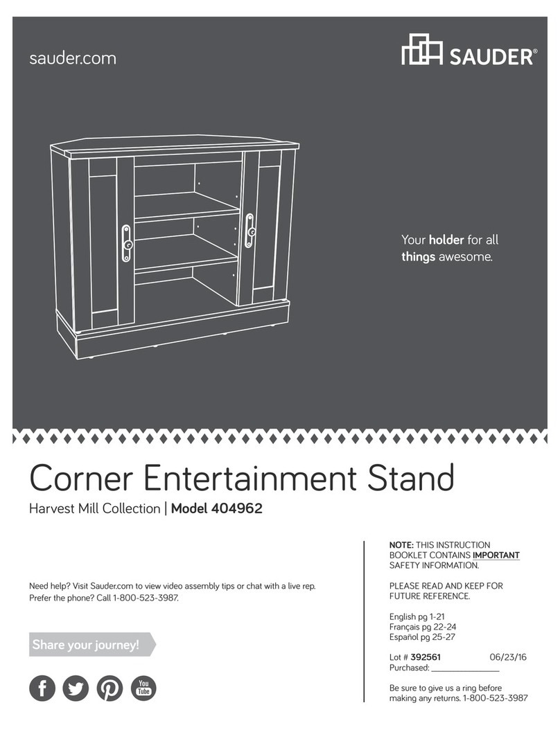
Credenza
Soft Modern Collection | 414986
Need help? Visit Sauder.com to view video assembly tips or chat with a live rep.
Prefer the phone? Call 1-800-523-3987.
Share your journey!
Your holder for all
things awesome.
sauder.com
Part Identification
Hardware Identification
Assembly Steps
Français
Español
Safety
Warranty
Use of a TV that is too heavy or lare is hazardous. A TV that is too heavy will create a risk of a tip-over that can cause severe injury or
death. A TV that is too lare for the available space miht be accidentally pushed or bumped o the furniture, or subject to tip-over.
• Check the size and weiht of your TV. Compare it to the diaram below – before you begin assembly!
• This Sauder unit is desined for use with televisions weihin less than 135 pounds. Never use with a TV that weihs more.
• The size of the television, front-to-back and side-to-side, must fit within the space defined in the diaram.
• Never place the front ede of the TV past the front ede of the TV support shelf (or stop moldin – if equipped)
• Never allow the sides of the TV to extend past the side edes of the TV support surface.
• If the TV has a CRT picture tube, the picture tube cone may extend past the rear of the support shelf.
• Be sure to apply the warnin label as instructed in the last assembly step. The label provides important safety related information.
3
4
5-21
22-24
25-27
28-30
31
Table of Contents
Hammer
Not actual size
No. 2 Phillips Screwdriver
Tip Shown Actual Size
Assembly Tools Required
135 lbs.
135 lbs.
72-1/4"
72-1/4"
19"
19"
WARNING
414986 www.sauder.com/servicesPae 2
Part Identification
åWhile not all parts are labeled, some of the parts will have a label or an inked letter on the ede
to help distinuish similar parts from each other. Use this part identification to help identify similar parts.
K RIGHT DRAWER FRONT (1)
L LEFT DRAWER FRONT (1)
M BASE (1)
N SIDE BASE (2)
O MOLDING (9)
M67 DRAWER BRACE (3)
D12 RIGHT DRAWER SIDE (3)
D13 LEFT DRAWER SIDE (3)
D115 DRAWER BACK (3)
D723 DRAWER BOTTOM (3)
A RIGHT END (1)
B LEFT END (1)
C UPRIGHT (2)
D LOWER UPRIGHT (2)
E TOP (1)
F BOTTOM (1)
G SHELF (1)
H BACK (1)
I BRACE (1)
J DRAWER FRONT (1)
A
B
C
C
D
D
E
F
G
H
I
J
K
L
M
N
N
O
O
O
D115
D723
D13
D12
414986www.sauder.com/services Pae 3
Now you know
our ABCs.
M67
Hardware Identification
åScrews are shown actual size. You may receive extra hardware with your unit.
35GA CABINET RIGHT - 3 35GB CABINET LEFT - 3 35GC DRAWER RIGHT - 3 35GD DRAWER LEFT - 3
1F HIDDEN CAM - 15 2F CAM DOWEL - 15 10F TWIST-LOCK®FASTENER - 8
10A SLIDE CAM - 6
(Refer to the last step for proper location and application)
31G CORNER BRACKET - 4
4G METAL BRACKET - 4 84K PULL - 3
3M ANTI-SKID PAD - 1 1N NAIL - 42 36P CAM COVER - 4
29M BUMPER CARD - 2
3S GOLD 5/16" FLAT HEAD SCREW - 26
2S BLACK 1-7/8" FLAT HEAD SCREW - 8
12S BROWN 1" FLAT HEAD SCREW - 36
1S BLACK 9/16" LARGE HEAD SCREW - 38
4L WARNING LABEL - 1
WARNING
Never use this furniture with a TV that is too
large or too heavy. Severe injury or death
can occur.The TV and furniture will be
unstable and may tip.
-The TV must less than 135 lbs.
-The base of the TV must be able to sit
completely on this shelf.
-Refer to instruction book for complete safety
information.
Note: This is a permanent label. Do not try
to remove. Surface will be damaged.
02/ 02 2 6 9 2 3 2 269232
414986 www.sauder.com/servicesPae 4
30S BLACK 1-9/16" FLAT HEAD SCREW - 15
Step 1
10F
(8 used)
A
B
Do not tihten the TWIST-LOCK® FASTENERS in this step.
å Assemble your unit on a carpeted floor or on the empty
carton to avoid scratchin your unit or the floor.
å To bein assembly, push a SAUDER TWIST-LOCK®
FASTENER (10F) into the lare holes in the ENDS (A
and B). Repeat this step for the SHELF (G).
Look for this icon. It means a
video assembly tip is available at
www.sauder.com/services/tips
414986www.sauder.com/services Pae 5
Some assembly
(and snacks) required.
Scan this QR code or go to this address:
http://qr.sauder.com/?ID=1360
to watch a video on how to assemble your unit.
Step
å Push fifteen HIDDEN CAMS (1F) into the UPRIGHTS (C
and D), BOTTOM (F), and DRAWER BRACES (M67). Then,
insert the metal end of a CAM DOWEL (2F) into each
HIDDEN CAM.
Step 2
Insert the metal end of the CAM
DOWEL into the HIDDEN CAM.
Arrow
Do not tihten the HIDDEN CAMS in this step.
(15 used)
(15 used)
Arrow
1F
2F
Arrow
1F
2F
C
C
D
D
F
414986 www.sauder.com/servicesPae 6
M67
M67
M67
StepStep 3
å Fasten a CABINET RIGHT (35GA) to the RIGHT END (A)
and a CABINET LEFT (35GB) to the LEFT END (B). Use
four GOLD 5/16” FLAT HEAD SCREWS (3S) throuh
holes #1 and #3.
1
2
3
Surface with
TWIST-LOCK
®
FASTENERS
Surface with
TWIST-LOCK
®
FASTENERS
B
A
GOLD 5/16" FLAT HEAD SCREW
(4 used in this step)
3S
Roller end
Roller end
1
2
3
414986www.sauder.com/services Pae 7
Step 4
å Fasten the CABINET RIGHTS (35GA) and CABINET
LEFTS (35GB) to the LOWER UPRIGHTS (D). Use eiht
GOLD 5/16” FLAT HEAD SCREWS (3S) throuh holes #1
and #3.
Finished ede
Finished ede
GOLD 5/16" FLAT HEAD SCREW
(8 used in this step)
3S
Roller end
Roller end
Roller end
Roller end
Surface with
HIDDEN CAMS
Surface without
HIDDEN CAMS
D
D
1
2
3
1
2
3
1
2
3
1
2
3
414986 www.sauder.com/servicesPae 8
Step 5
å Fasten the UPRIGHTS (C) to the TOP (E). Tihten four
HIDDEN CAMS.
Finished ede
Start Tighten
Arrow
Minimum
190 derees
Maximum
210 derees
Arrow
Caution
Risk of damae or
injury. HIDDEN CAMS
must be completely
tihtened. HIDDEN
CAMS that are not
completely tihtened
may loosen, and parts
may separate. To
completely tihten:
Surface with
HIDDEN CAMS
Surface with
HIDDEN CAMS
Lon finished ede
Surface
with holes
C
C
E
Do not stand the unit upriht without the
BACK fastened. The unit may collapse.
Caution
!
414986www.sauder.com/services Pae 9
Step
å Fasten the SHELF (G) to the UPRIGHTS (C). Use four
BLACK 1-7/8” FLAT HEAD SCREWS (2S).
Step 6
BLACK 1-7/8" FLAT HEAD SCREW
(4 used in this step)
2S
Surface with TWIST-LOCK
®
FASTENERS
Finished ede
C
C
G
414986 www.sauder.com/servicesPae 10
Step 7
å Fasten the LOWER UPRIGHTS (D) to the SHELF (G).
Tihten four HIDDEN CAMS.
å Fasten the BOTTOM (F) to the LOWER UPRIGHTS (D).
Use four BLACK 1-7/8” FLAT HEAD SCREWS (2S).
Finished ede
Surface with
HIDDEN CAMS
Surface with
HIDDEN CAMS
D
D
G
Arrow
Minimum
190 derees
Maximum
210 derees
Surface with
HIDDEN CAMS
F
BLACK 1-7/8" FLAT HEAD SCREW
(4 used in this step)
2S
Finished ede
414986www.sauder.com/services Pae 11
Step
å Fasten the ENDS (A and B) to the TOP (E),
BOTTOM (F), and SHELF (G). Tihten eiht
TWIST-LOCK® FASTENERS and four HIDDEN
CAMS.
Step 8
Arrow
Minimum
190 derees
Maximum
210 derees
How to use the SAUDER TWIST-LOCK®FASTENER
1. Insert the dowel end of the FASTENER into the hole of the
adjoinin part.
NOTE: The dowel end of the FASTENER must remain fully
inserted in the hole of the adjoinin part while lockin the
FASTENER.
2. Tihten the FASTENER with a Phillips screwdriver as tiht
as possible.
Dowel end
A
B
E
F
G
Surface with TWIST-LOCK® FASTENERS
Surface with TWIST-LOCK®
FASTENERS
Roller end
Roller end
414986 www.sauder.com/servicesPae 12
StepStep 9
å Fasten four CORNER BRACKETS (31G) to the BRACE (I) and
BASE (M). Use eiht BLACK 9/16” LARGE HEAD SCREWS (1S).
å Fasten four METAL BRACKETS (4G) to the BRACE (I) and
BASE (M). Use four BLACK 9/16” LARGE HEAD SCREWS (1S).
å NOT
E: Be sure the BRACKETS are even with the edes of
the BRACE and BASE.
4G
31G
31G
BLACK 9/16" LARGE HEAD SCREW
(12 used in this step)
1S
I
M
414986www.sauder.com/services Pae 13
Step
å Fasten the BRACE (I) and BASE (M) to the BOTTOM (F).
Use twelve BLACK 9/16” LARGE HEAD SCREWS (1S)
throuh the BRACKETS on the BRACE and BASE and
into the BOTTOM.
å Fasten the SIDE BASES (N) to the CORNER BRACKETS
on the BRACE (I) and BASE (M). Use eiht BLACK 9/16”
LARGE HEAD SCREWS (1S).
Step 10
BLACK 9/16" LARGE HEAD SCREW
(20 used in this step)
1S
N
N
I
F
M
414986 www.sauder.com/servicesPae 14
Hey! It's startin to look
like somethin!
StepStep 11
å Carefully turn your unit over onto its front edes. Lay the
BACK (H) over your unit.
å Make equal marins alon all four edes of the BACK (H).
Push on opposite corners of your unit if needed to make it
“square”.
å Fasten the BACK (H) to your unit usin the NAILS (1N).
å NOTE: Be sure to tap NAILS into the holes that line up over
the LOWER UPRIGHTS (D).
These holes must line up over
the LOWER UPRIGHTS (D).
NAIL
(42 used in this step)
1N
H
Do not stand the unit upriht without the
BACK fastened. The unit may collapse.
Caution
414986www.sauder.com/services Pae 15
Step
å Fasten the RIGHT DRAWER FRONT (K) to three
MOLDINGS (O). Use twelve BROWN 1” FLAT HEAD
SCREWS (12S).
å NOTE: Be sure to position the MOLDINGS exactly as
shown in the enlared diaram.
å Repeat this step for the other DRAWER FRONTS (J and L).
Step 12
Surface with rooves
K
O
O
O
BROWN 1" FLAT HEAD SCREW
(36 used in this step)
12S
Unfinished
surface
414986 www.sauder.com/servicesPae 16
StepStep 13
å Insert the DRAWER SIDES (D12 and D13 ) at an angle
into the slot at each end of the DRAWER FRONT (K ).
å Slide the DRAWER BOTTOM (D723) into the grooves in
the DRAWER SIDES (D12 and D13) and DRAWER FRONT (K).
å Fasten the DRAWER BRACE (M67) to the DRAWER
FRONT (K). Tighten one HIDDEN CAM.
å Fasten the DRAWER BACK (D115) to the DRAWER
SIDES (D12 and D13) and DRAWER BRACE (M67). Use five
BLACK 1-9/16” FLAT HEAD SCREWS (30S). Repeat this
step for the other DRAWERS (J and L).
The tabs should insert freely into the
slots. Gently tilt the DRAWER SIDES side
to side until the tabs slip into the slots.
UNFINISHED
12
34
Be sure the DRAWER
BOTTOM inserts into the
DRAWER FRONT roove.
With the palm of your hand, tap the
DRAWER BOTTOM down into the roove.
K
D12
D723
D115
D13
K
K
D12
D13
D12
D13
Groove
Arrow
Minimum
190 derees
Maximum
210 derees
Surface with
HIDDEN CAM
VIEW THE T-LOCK BOX VIDEO
414986www.sauder.com/services Pae 17
M67
M67
30S
Start each screw a few turns before
completely tihtenin any of them.
BLACK 1-9/16" FLAT HEAD SCREW
(15 used in this step)
Step
å Insert a SLIDE CAM (10A) into the DRAWER SIDES (D12
and D13).
å Fasten a DRAWER RIGHT (35GC) to the DRAWER RIGHT
SIDE (D12) and a DRAWER LEFT (35GD) to the DRAWER
LEFT SIDE (D13). Use four GOLD 5/16” FLAT HEAD
SCREWS (3S) throuh holes #1 and #3.
å NOTE: The screw head in the CAM must be visible
throuh the slotted hole in the SLIDE.
å Repeat this step for the other drawers.
Step 14
D12
D13
10A
10A
Screw head - turn CAM to line up holes
in SLIDES with holes in DRAWER SIDES.
Roller end
Roller end
GOLD 5/16" FLAT HEAD SCREW
(12 used in this step)
3S
1
2
3
1
2
3
414986 www.sauder.com/servicesPae 18
Step 15
å Fasten a PULL (84K) to the RIGHT DRAWER FRONT (K).
Use two BLACK 9/16” LARGE HEAD SCREWS (1S).
å Peel a BUMPER from the BUMPER CARD (29M) and stick
it on the PULL (84K) as shown.
å Repeat this step for the other drawers.
84K
29M
K
BLACK 9/16" LARGE HEAD SCREW
(six used in this step)
1S
414986www.sauder.com/services Pae 19
Step 16
å Carefully stand your unit upriht.
å To insert the drawer into your unit, tip the front of the drawer down and drop the rollers on the drawer behind the rollers on
the unit. Lift the front of the drawer up and slide it into the unit.
å Push a CAM COVER (36P) onto each visible HIDDEN CAM in the UPRIGHTS (C).
å Apply the WARNING LABEL (4L) to the TOP (E). You should be able to read the label when the TV is removed from the
unit. When the TV is in place, it should hide the label. Peel o the backin and apply the label as shown in the diaram.
å NOTE: This is a permanent label intended to last for the life of the product. Once applied, do not try to remove it.
å To help prevent the TV from slidin, place the ANTI-SKID PAD (3M) under the front support of the TV or divide amon the
front supports if more than one.
135 lbs.
C
CE
25 lbs.
25 lbs.
60 lbs. total
25 lbs.
WARNING
Never use this furniture with a TV that is too
lare or too heavy. Severe injury or death can
occur. The TV and furniture will be unstable
and may tip.
- The TV must weih less than 135 lbs.
- The base of the TV must be able to sit
completely on this shelf.
(4 used)
To cover HIDDEN CAMS.
36P
3M
4L
414986 www.sauder.com/servicesPae 20

Other Sauder Indoor Furnishing manuals

Sauder 401323 User manual

Sauder

Sauder 401323 User manual

Sauder Briarbrook 430077 User manual

Sauder

Sauder Briarbrook 430077 User manual

Sauder 402159 User manual

Sauder

Sauder 402159 User manual

Sauder Shoal Creek 409714 User manual

Sauder

Sauder Shoal Creek 409714 User manual

Sauder 416407 User manual

Sauder

Sauder 416407 User manual

Sauder Palladia Highboy 411626 User manual

Sauder

Sauder Palladia Highboy 411626 User manual

Sauder Englewood 426918 User manual

Sauder

Sauder Englewood 426918 User manual
Sauder 414356 User manual

Sauder

Sauder 414356 User manual

Sauder Shoal Creek 411222 User manual

Sauder

Sauder Shoal Creek 411222 User manual

Sauder OFFICE WORKS AFFIRM 427430 User manual

Sauder

Sauder OFFICE WORKS AFFIRM 427430 User manual

Sauder Cannery Bridge 415910 User manual

Sauder

Sauder Cannery Bridge 415910 User manual

Sauder 416519 User manual

Sauder

Sauder 416519 User manual

Sauder 423731 User manual

Sauder

Sauder 423731 User manual

Sauder County Line 417771 User manual

Sauder

Sauder County Line 417771 User manual

Sauder Clifford Place 433360 User manual

Sauder

Sauder Clifford Place 433360 User manual

Sauder 420406 User manual

Sauder

Sauder 420406 User manual

Sauder Anda Norr 427707 User manual

Sauder

Sauder Anda Norr 427707 User manual

Sauder Heritage Hill 109843 User manual

Sauder

Sauder Heritage Hill 109843 User manual

Sauder New Grange 419142 User manual

Sauder

Sauder New Grange 419142 User manual

Sauder Harbor View 415002 User manual

Sauder

Sauder Harbor View 415002 User manual

Sauder 404943 User manual

Sauder

Sauder 404943 User manual

Sauder North Avenue 426016 User manual

Sauder

Sauder North Avenue 426016 User manual

Sauder Shoal Creek 408920 User manual

Sauder

Sauder Shoal Creek 408920 User manual

Sauder August Hill 433851 User manual

Sauder

Sauder August Hill 433851 User manual

Popular Indoor Furnishing manuals by other brands

Home Decorators Collection SK19246E-V-1 Use and care guide

Home Decorators Collection

Home Decorators Collection SK19246E-V-1 Use and care guide

Muckle Mannequins HQ-BOP-1 instruction manual

Muckle Mannequins

Muckle Mannequins HQ-BOP-1 instruction manual

ZillionSource ZillionSense ZS-100 quick guide

ZillionSource

ZillionSource ZillionSense ZS-100 quick guide

Vivo DESK-SHELF24C instruction manual

Vivo

Vivo DESK-SHELF24C instruction manual

dellonda DH47 manual

dellonda

dellonda DH47 manual

Meble Wojcik HOBBY PRO-018-3101 Assembly instructions

Meble Wojcik

Meble Wojcik HOBBY PRO-018-3101 Assembly instructions

Geuther Stone 1148WK Instructions for assembly and use

Geuther

Geuther Stone 1148WK Instructions for assembly and use

fantastic furniture Sonoma Utility 3 Shelf manual

fantastic furniture

fantastic furniture Sonoma Utility 3 Shelf manual

Argos WOW 152/7252 Assembly lnstructions

Argos

Argos WOW 152/7252 Assembly lnstructions

Golden Technologies DeLuna Titan owner's manual

Golden Technologies

Golden Technologies DeLuna Titan owner's manual

KENAY Cube KAN-1375 manual

KENAY

KENAY Cube KAN-1375 manual

VIBO EDS 1150 Assembling instructions

VIBO

VIBO EDS 1150 Assembling instructions

VIV DESK-V201G-CH instruction manual

VIV

VIV DESK-V201G-CH instruction manual

Ostermann REDOCOL e-Desk Pro 90 Extension 90 Assembly & operation manual

Ostermann

Ostermann REDOCOL e-Desk Pro 90 Extension 90 Assembly & operation manual

Furniture of America CM7129Q Assembly instructions

Furniture of America

Furniture of America CM7129Q Assembly instructions

Rauch M2513 Assembly instructions

Rauch

Rauch M2513 Assembly instructions

calligaris SEATTLE CS/6004 manual

calligaris

calligaris SEATTLE CS/6004 manual

Pitarch 1007 Assembly instructions

Pitarch

Pitarch 1007 Assembly instructions

manuals.online logo
manuals.online logoBrands
  • About & Mission
  • Contact us
  • Privacy Policy
  • Terms and Conditions

Copyright 2025 Manuals.Online. All Rights Reserved.