manuals.online logo
Brands
  1. Home
  2. •
  3. Brands
  4. •
  5. Sauder
  6. •
  7. Indoor Furnishing
  8. •
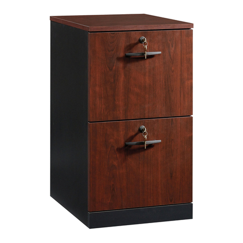
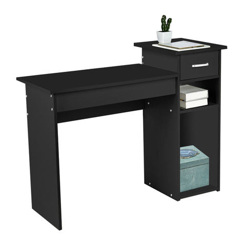
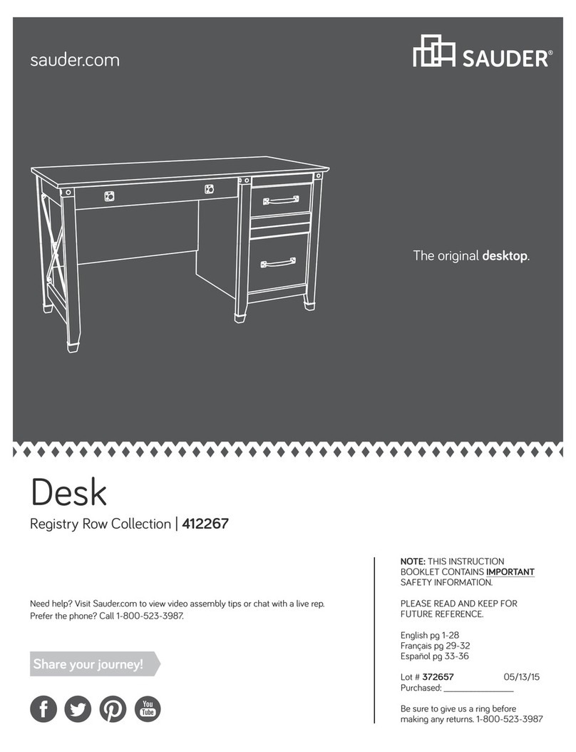
  9. Sauder Steel River Series User manual

Sauder Steel River Series User manual

sauder.com
NOTE: THIS INSTRUCTION
BOOKLET CONTAINS IMPORTANT
SAFETY INFORMATION.
PLEASE READ AND KEEP FOR
FUTURE REFERENCE.
sauder.com
CONTACT US FIRST
BEFORE MAKING ANY RETURNS TO THE STORE.
sauder.com
CONTACT US FIRST
BEFORE MAKING ANY RETURNS TO THE RETAILER.
Visit sauder.com/service to order replacement parts, view video assembly tips, or chat with a live rep.
Prefer the phone? Give us a ring at 1-800-445-1527.
Customer Service is available Monday-Friday - 9 a.m. to 5:30 p.m. EST (except holidays)
Sauder.com
Share your journey!
English pg 1-49
Français pg 50-54
Español pg 55-59
Lot # 551945 09/17/20
Purchased: __________________
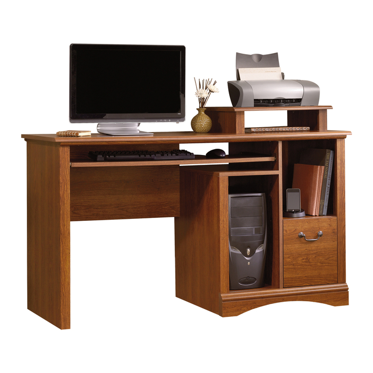
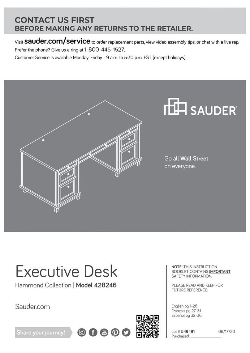
Desk
Steel River Collection | Model 427652
For all your
newfangled gadgetry.
Part Identification
Hardware Identification
Hardware Usage Guide
Assembly Steps
Français
Español
Safety
Warranty
Hammer
Not actual size
No. 2 Phillips Screwdriver
Tip Shown Actual Size
Table of Contents Assembly Tools Required
3
4-5
6
7-45
46-50
51-55
56-58
59
Page 2 www.sauder.com/service 427652
Part Identification
åWhile not all parts are labeled, some of the parts will have a label or an inked letter on the edge
to help distinguish similar parts from each other. Use this part identification to help identify similar parts.
Now you know
our ABCs.
A TOP (1)
B LARGE BACK (1)
C BOTTOM (2)
D SMALL BACK (2)
E LEFT END (1)
F LEFT UPRIGHT (1)
G RIGHT UPRIGHT (1)
H RIGHT END (1)
J RAIL SUPPORT (6)
K LEFT END FRAME (1)
L LEFT UPRIGHT FRAME (1)
N RIGHT UPRIGHT FRAME (1)
O RIGHT END FRAME (1)
P SMALL SKIRT (4)
Q FRONT MOLDING (2)
R FRONT LARGE MOLDING (1)
S BACK LARGE SKIRT (1)
T LARGE DRAWER FRONT (1)
U LEFT LARGE DRAWER SIDE (1)
V RIGHT LARGE DRAWER SIDE (1)
X LARGE DRAWER BACK (1)
Y DRAWER BOTTOM (3)
Z FILE GLIDE HOLDER (1)
AA SMALL DRAWER FRONT (2)
BB SMALL LEFT DRAWER SIDE (2)
CC SMALL RIGHT DRAWER SIDE (2)
DD SMALL DRAWER BACK (2)
A
B
C
C
D
D
E
F
G
H
J
J
J
JJ
J
J
K
L
N
O
Q
Q
R
S
P
P
P
P
T
Y
Y
V
U
X
Z
Y
AA
BB
CC
DD
AA
BB
DD
CC
Page 3www.sauder.com/service427652
Hardware Identification
METAL BRACKET -20
11 APPLIQUE CARD - 4
12 13 FILE GLIDE - 2
(EXTENSION SET SHOWN SEPARATED)
1EXTENSION RAIL - 2 2EXTENSION SLIDE - 2
WOOD DOWEL -4
9KNOB and
BACKPLATE -3
10
CAM SCREW - 24
8
CABINET RIGHT - 2
3CABINET LEFT - 2
4
HIDDEN CAM - 24
7
DRAWER RIGHT - 2
5DRAWER LEFT - 2
6
Page 4 www.sauder.com/service 427652
2" PAN HEAD SCREW - 12
14 1-3/16" PAN HEAD SCREW - 14
15
1" FLAT HEAD SCREW - 12
16 1" MACHINE SCREW - 3
17
1/2" PAN HEAD SCREW - 66
18 1/2" FLAT HEAD SCREW - 24
19
åScrews are shown actual size. You may receive extra hardware with your unit.
Hardware Usage Guide
HOW TO USE A HIDDEN CAM & CAM SCREW OR CAM DOWEL
NOTE: Various CAM SCREWS or a CAM DOWEL may be used.
Cam Screws Cam Dowel
Turn the CAM SCREW or
gently tap the CAM DOWEL
until the shoulder is against
the surface of the part.
1.
Hidden CamHidden Cam
Arrow
Push a HIDDEN CAM into
the part. The arrow in the
HIDDEN CAM must point
toward the hole in the
edge of the board.
Hole
2.
3.
1
2
Insert the CAM SCREW or CAM DOWEL into the
HIDDEN CAM. Tighten the HIDDEN CAM.
Page 5www.sauder.com/service427652
Step 1 Look for this icon. It means a video assembly tip is
available at www.sauder.com/service/tips
Find the numbered video or scan the QR code.
å Assemble your unit on a carpeted floor or on the empty
carton to avoid scratching your unit or the floor.
å Turn two CAM SCREWS (8) into the LEFT END (E).
å Fasten six METAL BRACKETS (11) to the LEFT END (E) and
LEFT END FRAME (K). Use six 1/2" PAN HEAD SCREWS (18).
K
E
11
11
11
8
1
1/2" PAN HEAD SCREW
(6 used in this step)
18
18
18
Page 6 www.sauder.com/service 427652
Step
å Fasten the LEFT END (E) to the LEFT END FRAME (K).
Use two 1/2" PAN HEAD SCREWS (18) through the
METAL BRACKETS and into the LEFT END FRAME.
å Fasten the LEFT END (E) to the LEFT END FRAME (K).
Use two 2" PAN HEAD SCREWS (14).
Step 2
K
E
2" PAN HEAD SCREW
(2 used in this step)
14
1/2" PAN HEAD SCREW
(2 used in this step)
18
Page 7www.sauder.com/service427652
Step
å Fasten a RAIL SUPPORT (J) to the LEFT END (E). Use two
1" FLAT HEAD SCREWS (16).
Step 3
E
J
This hole must be here.
Surface with more holes
1" FLAT HEAD SCREW
(2 used in this step)
16
Page 8 www.sauder.com/service 427652
Step
å Push two HIDDEN CAMS (7) into the LEFT UPRIGHT (F).
å Turn two CAM SCREWS (8) into the LEFT UPRIGHT (F).
å Fasten four METAL BRACKETS (11) to the LEFT UPRIGHT (F) and
LEFT UPRIGHT FRAME (L). Use four 1/2" PAN HEAD SCREWS (18).
Step 4
F
L
1
7
Arrow
11
18
1/2" PAN HEAD SCREW
(4 used in this step)
18
8
11
Page 9www.sauder.com/service427652
Step
å Fasten the LEFT UPRIGHT (F) to the LEFT UPRIGHT FRAME (L).
Use two 1/2" PAN HEAD SCREWS (18) though the METAL
BRACKETS and into the LEFT UPRIGHT FRAME.
å Fasten the LEFT UPRIGHT (F) to the LEFT UPRIGHT FRAME (L).
Use two 2" PAN HEAD SCREWS (14).
Step 5
F
L
2" PAN HEAD SCREW
(2 used in this step)
14
1/2" PAN HEAD SCREW
(2 used in this step)
18
Surface with
HIDDEN CAMS
Page 10 www.sauder.com/service 427652
Step
å Fasten the RAIL SUPPORT (J) to the LEFT UPRIGHT (F).
Use two 1" FLAT HEAD SCREWS (16).
Step 6
1" FLAT HEAD SCREW
(2 used in this step)
16
This hole must be here.
Surface with more holes
F
J
Page 11www.sauder.com/service427652
Step
å Separate the EXTENSION SLIDES (2) from the EXTENSION RAILS (1) as shown in the upper diagram below. Be
prepared, the parts are greasy.
å Fasten the EXTENSION RAILS (1) to the RAIL SUPPORTS (J). Use four 1/2" FLAT HEAD SCREWS (19) through the
holes shown in the enlarged diagram.
å NOTE: For each EXTENSION RAIL, turn a SCREW into the hole shown in the enlarged diagram. Then, slide the inner
cartridge of the EXTENSION RAIL in to find the other hole that lines up with the hole in the END. Turn a SCREW into
this hole.
å NOTE: The EXTENSION SLIDES will be used later for the DRAWERS.
Step 7
K
L
J
J
1
1
12
1
Open end
Open end
Push the black lever in and pull the SLIDE from the RAIL.
Open end
1/2" FLAT HEAD SCREW
(4 used in this step)
19
Page 12 www.sauder.com/service 427652
Step
å Push four HIDDEN CAMS (7) into one of the
SMALL BACKS (D).
å Fasten the SMALL BACK (D) to the LEFT END (E). Tighten
two HIDDEN CAMS.
Step 8
D
K
E
1
Arrow
7
7
Arrow
Surface without
HIDDEN CAMS
Just think. The sooner
you do this, the sooner
you do something else.
Page 13www.sauder.com/service427652
Step
å Fasten the FRONT MOLDING (Q) to the LEFT
END FRAME (K). Use a 1/2" PAN HEAD SCREW (18).
å Fasten the SMALL SKIRTS (P) to the LEFT END FRAME (K).
Use two 1/2" PAN HEAD SCREWS (18) through the METAL
BRACKETS and into the LEFT END FRAME.
Step 9
K
P
P
Page 14 www.sauder.com/service 427652
METAL BRACKET
must be closer to
this edge.
K
Q
18
METAL BRACKET
must be even
with this edge.
1/2" PAN HEAD SCREW
(3 used in this step)
18
Step
Page 15www.sauder.com/service427652
å Fasten the LEFT UPRIGHT (F) to the SMALL BACK (D).
Tighten two HIDDEN CAMS.
å Fasten the LEFT UPRIGHT FRAME (L) to the SMALL
SKIRTS (P) and FRONT MOLDING (Q). Use three 1/2"
PAN HEAD SCREWS (18).
Step 10
D
K
L
P
P
Q
F
1/2" PAN HEAD SCREW
(3 used in this step)
18
1
Step
å Fasten one of BOTTOMS (C) to the LEFT END FRAME (K),
LEFT UPRIGHT FRAME (L), and SMALL SKIRTS (P). Use six
1/2" PAN HEAD SCREWS (18) through the METAL BRACKETS
and into the BOTTOM.
Step 11
K
L
C
P
P
1/2" PAN HEAD SCREW
(6 used in this step)
18
Page 16 www.sauder.com/service 427652
Step
Page 17www.sauder.com/service427652
å Push two HIDDEN CAMS (7) into the RIGHT UPRIGHT (G).
å Turn two CAM SCREWS (8) into the RIGHT UPRIGHT (G).
å Fasten four METAL BRACKETS (11) to the RIGHT UPRIGHT (G). and
RIGHT UPRIGHT FRAME (N). Use four 1/2" PAN HEAD SCREWS (18)
Step 12
G
N
1
7
Arrow
8
11
11
18
1/2" PAN HEAD SCREW
(4 used in this step)
18
Step
å Fasten the RIGHT UPRIGHT (G) to the RIGHT
UPRIGHT FRAME (N). Use two 1/2" PAN HEAD SCREWS (18)
through the METAL BRACKETS and into the RIGHT
UPRIGHT FRAME.
å Fasten the RIGHT UPRIGHT (G) to the RIGHT
UPRIGHT FRAME (N). Use two 2" PAN HEAD SCREWS (14)
Step 13
G
N
2" PAN HEAD SCREW
(2 used in this step)
14
1/2" PAN HEAD SCREW
(2 used in this step)
18
Page 18 www.sauder.com/service 427652
Surface with
HIDDEN CAMS
Step
Page 19www.sauder.com/service427652
å Fasten two RAIL SUPPORTS (J) to the RIGHT UPRIGHT (G).
Use four 1" FLAT HEAD SCREWS (16).
Step 14
G
J
J
1" FLAT HEAD SCREW
(4 used in this step)
16
Surface with more holes
This hole must be here.
16
Step
å Turn two CAM SCREWS (8) into the RIGHT END (H).
å Fasten six METAL BRACKETS (11) to the RIGHT END (H) and
RIGHT END FRAME (O). Use six 1/2" PAN HEAD SCREWS (18).
Step 15
H
O
1
8
1/2" PAN HEAD SCREW
(6 used in this step)
18
11
11
18
11
18
Page 20 www.sauder.com/service 427652

This manual suits for next models

1

Other Sauder Indoor Furnishing manuals

Sauder Dakota Pass 422592 User manual

Sauder

Sauder Dakota Pass 422592 User manual

Sauder Lateral File Boulevard Cafe 427345 User manual

Sauder

Sauder Lateral File Boulevard Cafe 427345 User manual

Sauder 408761 User manual

Sauder

Sauder 408761 User manual

Sauder 419517 User manual

Sauder

Sauder 419517 User manual

Sauder Nova Loft 423720 User manual

Sauder

Sauder Nova Loft 423720 User manual

Sauder Shoal Creek 408920 User manual

Sauder

Sauder Shoal Creek 408920 User manual

Sauder 420566 User manual

Sauder

Sauder 420566 User manual

Sauder Carson Forge 415572 User manual

Sauder

Sauder Carson Forge 415572 User manual

Sauder 410794 User manual

Sauder

Sauder 410794 User manual

Sauder 418269 User manual

Sauder

Sauder 418269 User manual

Sauder Harbor View 158015 User manual

Sauder

Sauder Harbor View 158015 User manual

Sauder Shoal Creek 411201 User manual

Sauder

Sauder Shoal Creek 411201 User manual

Sauder Harbor View 401328 User manual

Sauder

Sauder Harbor View 401328 User manual

Sauder Heritage Hill 109872 User manual

Sauder

Sauder Heritage Hill 109872 User manual

Sauder 430237 User manual

Sauder

Sauder 430237 User manual

Sauder 420612 User manual

Sauder

Sauder 420612 User manual

Sauder Pinwheel 421886 User manual

Sauder

Sauder Pinwheel 421886 User manual

Sauder Boulevard Cafe 421957 User manual

Sauder

Sauder Boulevard Cafe 421957 User manual

Sauder Palladia 411835 User manual

Sauder

Sauder Palladia 411835 User manual

Sauder Harbor View 423661 User manual

Sauder

Sauder Harbor View 423661 User manual

Sauder Shoal Creek 412093 User manual

Sauder

Sauder Shoal Creek 412093 User manual

Sauder Office Port Series User manual

Sauder

Sauder Office Port Series User manual

Sauder 414254 User manual

Sauder

Sauder 414254 User manual

Sauder Edge Water 409047 User manual

Sauder

Sauder Edge Water 409047 User manual

Popular Indoor Furnishing manuals by other brands

Mantua Manufacturing Universal Grab-and-Go Assembly instructions

Mantua Manufacturing

Mantua Manufacturing Universal Grab-and-Go Assembly instructions

VS 910 Series operating instructions

VS

VS 910 Series operating instructions

Ergotron Zido ZGBCG user guide

Ergotron

Ergotron Zido ZGBCG user guide

Suncast BMC3601 Assembly instructions

Suncast

Suncast BMC3601 Assembly instructions

Takara Belmont Legacy 91 operating manual

Takara Belmont

Takara Belmont Legacy 91 operating manual

Safavieh Furniture FOX7006 manual

Safavieh Furniture

Safavieh Furniture FOX7006 manual

Aspace 2022 instructions

Aspace

Aspace 2022 instructions

EKVIP 023760 operating instructions

EKVIP

EKVIP 023760 operating instructions

Furniture of America CM2815 Assembly instructions

Furniture of America

Furniture of America CM2815 Assembly instructions

Pacific Casual Pendleton II 146-054-7DB1 Assembly instructions

Pacific Casual

Pacific Casual Pendleton II 146-054-7DB1 Assembly instructions

Jysk BROBY 3606121 manual

Jysk

Jysk BROBY 3606121 manual

AKANTE DROP CT380 Assembly instructions

AKANTE

AKANTE DROP CT380 Assembly instructions

Amart Furniture KOMBIE MKII 62783 Assembly instruction

Amart Furniture

Amart Furniture KOMBIE MKII 62783 Assembly instruction

Rapidline Deluxe Infinity Profile Leg Single Workstation with... Assembly instructions

Rapidline

Rapidline Deluxe Infinity Profile Leg Single Workstation with... Assembly instructions

Blanco Precision MicroEdge 516202 Specification sheet

Blanco

Blanco Precision MicroEdge 516202 Specification sheet

Coaster Blake 511121 Assembly instructions

Coaster

Coaster Blake 511121 Assembly instructions

Lightolier Brisa FP14LEC specification

Lightolier

Lightolier Brisa FP14LEC specification

JAKO-O Etagenbett Bus Assembly instructions

JAKO-O

JAKO-O Etagenbett Bus Assembly instructions

manuals.online logo
manuals.online logoBrands
  • About & Mission
  • Contact us
  • Privacy Policy
  • Terms and Conditions

Copyright 2025 Manuals.Online. All Rights Reserved.