manuals.online logo
Brands
  1. Home
  2. •
  3. Brands
  4. •
  5. Sauder
  6. •
  7. Indoor Furnishing
  8. •
  9. Sauder Harvest Mill 404962 User manual

Sauder Harvest Mill 404962 User manual

NOTE: THIS INSTRUCTION
BOOKLET CONTAINS IMPORTANT
SAFETY INFORMATION.
PLEASE READ AND KEEP FOR
FUTURE REFERENCE.
English pg 1-21
Français pg 22-24
Español pg 25-27
Lot # 392561 06/23/16
Purchased: __________________
Be sure to give us a ring before
making any returns. 1-800-523-3987
Need help? Visit Sauder.com to view video assembly tips or chat with a live rep.
Prefer the phone? Call 1-800-523-3987.
Share your journey!
sauder.com
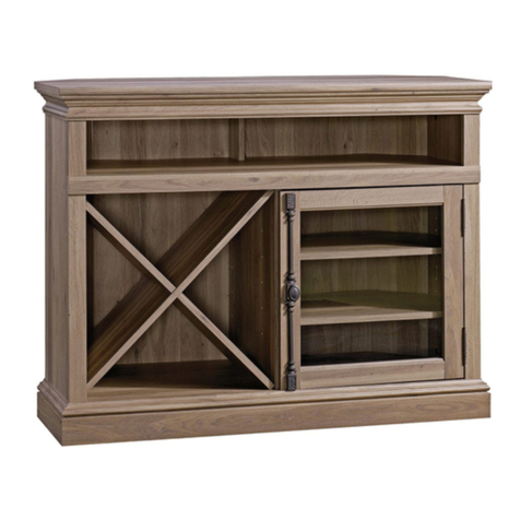
Corner Entertainment Stand
Harvest Mill Collection | Model 404962
Your holder for all
things awesome.
Table of Contents Assembly Tools Required
3
4
5-21
22-24
25-27
28-30
31
Part Identification
Hardware Identification
Assembly Steps
Français
Español
Safety
Warranty
Hammer
Not actual size
No. 2 Phillips Screwdriver
Tip Shown Actual Size
Use of a TV that is too heavy or large is hazardous. A TV that is too heavy will create a risk of a tip-over that can cause severe injury or
death. A TV that is too large for the available space might be accidentally pushed or bumped o the furniture, or subject to tip-over.
• Check the size and weight of your TV. Compare it to the diagram below – before you begin assembly!
• This Sauder unit is designed for use with televisions weighing less than 95 pounds. Never use with a TV that weighs more.
• The size of the television, front-to-back and side-to-side, must fit within the space defined in the diagram.
• Never place the front edge of the TV past the front edge of the TV support shelf (or stop molding – if equipped)
• Never allow the sides of the TV to extend past the side edges of the TV support surface.
• If the TV has a CRT picture tube, the picture tube cone may extend past the rear of the support shelf.
• Be sure to apply the warning label as instructed in the last assembly step. The label provides important safety related information.
WARNING
!
95 lbs.
95 lbs.
15-3/8"
15-3/8"
35-3/8"
35-3/8"
Skip the power trip.
This time.
404962 www.sauder.com/servicesPage 2
Part Identification
åWhile not all parts are labeled, some of the parts will have a label or an inked letter on the edge
to help distinguish similar parts from each other. Use this part identification to help identify similar parts.
A RIGHT END (1)
B LEFT END (1)
C RIGHT UPRIGHT (1)
D LEFT UPRIGHT (1)
E TOP (1)
F BOTTOM (1)
G STOP MOLDING (1)
H BACK (1)
I SMALL BACK (2)
J VALANCE (1)
K FRONT SKIRT (1)
L SIDE SKIRT (2)
M DOOR (2)
O SMALL ADJUSTABLE SHELF (2)
T LARGE ADJUSTABLE SHELF (2)
Now you know
our ABCs.
404962www.sauder.com/services Page 3
A
B
C
D
E
F
G
H
I
J
K
L
M
O
T
I
O
T
L
M
Hardware Identification
åScrews are shown actual size. You may receive extra hardware with your unit.
404962 www.sauder.com/servicesPage 4
FOOT - 2
23E
12E TACK GLIDE - 6 HIDDEN CAM - 12
1F CAM DOWEL - 8
2F CAM SCREW - 4
8F
METAL
BRACKET - 9
4G ANGLE
BRACKET - 2
27G PIVOT HINGE - 4
15H MAGNETIC
CATCH - 2
2I STRIKE
PLATE - 2
6I
WASHER - 2
9I KNOB - 2
13K BACKPLATE - 2
14K
(Refer to the last step for proper
location and application)
WARNING LABEL - 1
3L
WARNING
Never use this furniture with a TV that is too
large or too heavy. Severe injury or death
can occur.The TV and furniture will be
unstable and may tip.
-The TV must less than 95 lbs.
-The base of the TV must be able to sit
completely on this shelf.
-Refer to instruction book for complete
safety information.
Note: This is a permanent label. Do not try
to remove. Surface will be damaged.
02/ 02 269227
METAL PIN - 24
1R RUBBER SLEEVE - 16
2R
NAIL - 10
1N
BLACK 9/16" LARGE HEAD SCREW - 26
1S BLACK 1-7/8" FLAT HEAD SCREW - 8
2S
BLACK 1/2" FLAT HEAD SCREW - 2
11S GOLD 1" MACHINE SCREW - 2
50S
Step 1 Look for this icon. It means a
video assembly tip is available at
www.sauder.com/services/tips
å Assemble your unit on a carpeted floor or on the empty
carton to avoid scratching your unit or the floor.
å Push eight HIDDEN CAMS (1F) into the ENDS (A and B)
and UPRIGHTS (C and D). Then, insert the metal end of a
CAM DOWEL (2F) into each HIDDEN CAM.
404962www.sauder.com/services Page 5
Insert the metal end of the CAM
DOWEL into the HIDDEN CAM.
Arrow
Do not tighten the HIDDEN CAMS in this step.
D
Arrow
1F
2F
(8 used)
A
B
C
Step 2
å Push four HIDDEN CAMS (1F) into the TOP (E).
404962 www.sauder.com/servicesPage 6
Arrow
The arrow in the HIDDEN
CAM must point toward the
hole in the edge of the board.
Hole
E
Arrow
1F
Some assembly
(and snacks) required.
å Turn four CAM SCREWS (8F) into the STOP MOLDING (G).
Step 3
404962www.sauder.com/services Page 7
G
8F
Step 4
å Fasten the STOP MOLDING (G) to the TOP (E). Tighten
four HIDDEN CAMS.
404962 www.sauder.com/servicesPage 8
G
E
1
2
Surface with holes
Surface with HIDDEN CAMS
å Insert eight METAL PINS (1R) into the exact holes shown
in the ENDS (A and B) and UPRIGHTS (C and D).
å Push the MAGNETIC CATCHES (2I) into the holes on
the UPRIGHTS (C and D).
Step 5
404962www.sauder.com/services Page 9
D
C
B
A
2I
2I
1R
1R
1R
Surface without
HIDDEN CAMS
Surface without
HIDDEN CAMS
For adjustment, turn barrel counter-clockwise.
Surface with
HIDDEN CAMS
Step 6
å Fasten the LEFT END (B) to the TOP (E). Tighten two
HIDDEN CAMS.
404962 www.sauder.com/servicesPage 10
B
E
Start Tighten
Arrow
Minimum
190 degrees
Caution
Risk of damage or
injury. HIDDEN CAMS
must be completely
tightened. HIDDEN
CAMS that are not
completely tightened
may loosen, and parts
may separate. To
completely tighten:
Arrow
Maximum
210 degrees
G
Surface
with holes
Edge with METAL PINS
Surface with
HIDDEN CAMS
å Push a SMALL BACK (I) onto the METAL PINS in the
LEFT END (B).
å Fasten the LEFT UPRIGHT (D) to the TOP (E) and SMALL
BACK (I). Tighten two HIDDEN CAMS.
å NOTE: Be sure the METAL PINS in the LEFT UPRIGHT
insert into the holes in the SMALL BACK.
Step 7
404962www.sauder.com/services Page 11
E
I
D
B
Edge with METAL PINS
Arrow
Minimum
190 degrees
Maximum
210 degrees
Surface with
HIDDEN CAMS
Step 8
å Fasten the RIGHT END (A) to the TOP (E). Tighten two
HIDDEN CAMS.
å Push the SMALL BACK (I) onto the METAL PINS in the
RIGHT END (A).
404962 www.sauder.com/servicesPage 12
Arrow
Minimum
190 degrees
Maximum
210 degrees
A
E
Surface
without
HIDDEN
CAMS
I
Edge with METAL PINS
Don't worry. It isn't
Rome. This can be built
in a day.
å Fasten the RIGHT UPRIGHT (C) to the TOP (E) and
SMALL BACK (I). Tighten two HIDDEN CAMS.
å NOTE: Be sure the METAL PINS in the RIGHT UPRIGHT
insert into the holes in the SMALL BACK.
å Fasten the BOTTOM (F) to the ENDS (A and B) and
UPRIGHTS (C and D). Use eight BLACK 1-7/8" FLAT
HEAD SCREWS (2S).
Step 9
404962www.sauder.com/services Page 13
Arrow
Minimum
190 degrees
Maximum
210 degrees
Edge with METAL PINS
A
E
B
D
C
F
BLACK 1-7/8" FLAT HEAD SCREW
(8 used in this step)
2S
Long finished edge
Surface with HIDDEN CAMS
Unfinished
surface
I
Step 10
å Fasten two ANGLE BRACKETS (27G) to the STOP MOLDING (G).
Use two BLACK 9/16" LARGE HEAD SCREWS (1S).
å Fasten the VALANCE (J) to the STOP MOLDING (G). Use two
BLACK 9/16" LARGE HEAD SCREWS (1S).
å NOTE: There are no pre-drilled holes in the VALANCE. The
SCREWS will tighten into the groove.
404962 www.sauder.com/servicesPage 14
BLACK 9/16" LARGE HEAD SCREW
(4 used in this step)
1S
27G
Groove
J
G
å Fasten nine METAL BRACKETS (4G) to the BOTTOM (F)
and both SIDE SKIRTS (L). Use nine BLACK 9/16" LARGE
HEAD SCREWS (1S).
å NOTE: Pay close attention to the position of the METAL
BRACKETS on the SIDE SKIRTS. Be sure the BRACKETS
are even with the edges of the SIDE SKIRTS.
Step 11
404962www.sauder.com/services Page 15
BLACK 9/16" LARGE HEAD SCREW
(9 used in this step)
1S
4G
4G
4G
4G
F
L
L
Finished edge
Step 12
å Fasten the SKIRTS (K and L) to the BOTTOM (F). Use
seven BLACK 9/16" LARGE HEAD SCREWS (1S).
å Fasten the SIDE SKIRTS (L) to the FRONT SKIRT (K). Use
two BLACK 9/16" LARGE HEAD SCREWS (1S).
404962 www.sauder.com/servicesPage 16
BLACK 9/16" LARGE HEAD SCREW
(9 used in this step)
1S
F
K
L
L
Finished edge
Finished edge
å Tap six TACK GLIDES (12E) into the SKIRTS (K and L).
å Insert the FEET (23E) into the large holes on the BOTTOM (F).
Step 13
404962www.sauder.com/services Page 17
23E
23E
F
12E
L
L
K
If you're doing this to
help a friend, don't
leave without a bite.
Step 14
å Carefully turn your unit over onto its front edges. Lay the
BACK (H) over your unit with the unfinished surface facing up.
å Make equal margins along all four edges of the BACK (H). Push
on opposite corners of your unit if needed to make it "square".
å Fasten the BACK (H) to your unit using the NAILS (1N).
å NOTE: Perforations have been provided for access through the
BACK. Carefully cut out the holes needed.
404962 www.sauder.com/servicesPage 18
Do not stand the unit upright without the
BACK fastened. The unit may collapse.
Caution
Unfinished surface
NAIL
(10 used in this step)
1N
H
å Fasten a PIVOT HINGE (15H) to each DOOR (M). Use two
BLACK 9/16" LARGE HEAD SCREWS (1S).
å Fasten a STRIKE PLATE (6I) to each DOOR (M). Use two
BLACK 1/2" FLAT HEAD SCREWS (11S).
Step 15
404962www.sauder.com/services Page 19
15H
15H
M
M
6I
6I
IMPORTANT: Only fasten one hinge to each door in this step.
BLACK 9/16" LARGE HEAD SCREW
(2 used for the PIVOT HINGES)
1S
BLACK 1/2" FLAT HEAD SCREW
(2 used for the STRIKE PLATES)
11S
Step 16
å Carefully stand your unit upright.
å Insert a free PIVOT HINGE (15H) through a WASHER (9I) and into the BOTTOM (F).
å Insert the PIVOT HINGE, which is fastened to the DOOR (M), into the hole in the
STOP MOLDING (G). You will need to tilt your DOOR slightly.
å Now, tip the DOOR in and fasten the free hinge to the DOOR. Use a BLACK 9/16"
LARGE HEAD SCREW (1S).
å Fasten a KNOB (13K) and BACKPLATE (14K) to the DOOR (M). Use a GOLD 1"
MACHINE SCREW (50S).
å NOTE: To make adjustments to the DOOR, loosen the SCREW in the PIVOT HINGE,
make needed adjustments, and tighten the SCREW.
å Repeat this step for the other DOOR.
404962 www.sauder.com/servicesPage 20
GOLD 1" MACHINE SCREW
(2 used in this step)
50S
G
F
M
9I
15H
14K
13K
BLACK 9/16" LARGE HEAD SCREW
(2 used for the PIVOT HINGES)
1S

Other Sauder Indoor Furnishing manuals
Sauder Edge Water Series User manual

Sauder

Sauder Edge Water Series User manual

Sauder 418647 User manual

Sauder

Sauder 418647 User manual

Sauder Office Works Affirm 426274 User manual

Sauder

Sauder Office Works Affirm 426274 User manual

Sauder 417886 User manual

Sauder

Sauder 417886 User manual

Sauder Whitaker Point 429369 User manual

Sauder

Sauder Whitaker Point 429369 User manual

Sauder Soft Modern 415007 User manual

Sauder

Sauder Soft Modern 415007 User manual

Sauder Viabella 420870 User manual

Sauder

Sauder Viabella 420870 User manual

Sauder Boulevard Cafe 420701 User manual

Sauder

Sauder Boulevard Cafe 420701 User manual

Sauder Via 401447 User manual

Sauder

Sauder Via 401447 User manual

Sauder Pogo 414433 User manual

Sauder

Sauder Pogo 414433 User manual

Sauder 410375 User manual

Sauder

Sauder 410375 User manual

Sauder 402905 User manual

Sauder

Sauder 402905 User manual

Sauder 427470 User manual

Sauder

Sauder 427470 User manual

Sauder Shoal Creek 408920 User manual

Sauder

Sauder Shoal Creek 408920 User manual

Sauder August Hill 426133 User manual

Sauder

Sauder August Hill 426133 User manual

Sauder OfficeWorks AFFIRM 426279 User manual

Sauder

Sauder OfficeWorks AFFIRM 426279 User manual

Sauder 402159 User manual

Sauder

Sauder 402159 User manual

Sauder Via 419609 User manual

Sauder

Sauder Via 419609 User manual

Sauder 411885 User manual

Sauder

Sauder 411885 User manual

Sauder 414724 User manual

Sauder

Sauder 414724 User manual

Sauder 409944 User manual

Sauder

Sauder 409944 User manual

Sauder 411802 User manual

Sauder

Sauder 411802 User manual

Sauder Summer Home Pantry 401867 User manual

Sauder

Sauder Summer Home Pantry 401867 User manual

Sauder Via 419708 User manual

Sauder

Sauder Via 419708 User manual

Popular Indoor Furnishing manuals by other brands

Otto MONA 53 Assembly instruction

Otto

Otto MONA 53 Assembly instruction

Next Hartford Flip Bed Assembly instructions

Next

Next Hartford Flip Bed Assembly instructions

Monarch Specialties I 2640T Assembly instructions

Monarch Specialties

Monarch Specialties I 2640T Assembly instructions

NEXERa 223805 Assembly instructions

NEXERa

NEXERa 223805 Assembly instructions

Forte TDHK235 manual

Forte

Forte TDHK235 manual

ATIM 411/78.1105.22E Assembly instructions

ATIM

ATIM 411/78.1105.22E Assembly instructions

Vivo CHAIR-S02M instruction manual

Vivo

Vivo CHAIR-S02M instruction manual

Costway HW63116 manual

Costway

Costway HW63116 manual

Spectrum GG Gaming Desk 37421 Assembly instructions

Spectrum

Spectrum GG Gaming Desk 37421 Assembly instructions

Amart Furniture SPARTACUS 51200 Assembly instruction

Amart Furniture

Amart Furniture SPARTACUS 51200 Assembly instruction

LAUNDREEZY LDS 70200 manual

LAUNDREEZY

LAUNDREEZY LDS 70200 manual

Evan furniture PERUGIA T13 Assembly instruction

Evan furniture

Evan furniture PERUGIA T13 Assembly instruction

Core Products VEGAS COFFEE TABLE VG902 Assembly instructions

Core Products

Core Products VEGAS COFFEE TABLE VG902 Assembly instructions

Steelcase Groupwork Flip-Top Table manual

Steelcase

Steelcase Groupwork Flip-Top Table manual

Hillsdale Furniture Casselberry 103650 Assembly instructions

Hillsdale Furniture

Hillsdale Furniture Casselberry 103650 Assembly instructions

Estate ESM1570SW Assembly/installation instructions

Estate

Estate ESM1570SW Assembly/installation instructions

Steve Silver KT800CC manual

Steve Silver

Steve Silver KT800CC manual

Seville Classics airLIFT OFF65927 manual

Seville Classics

Seville Classics airLIFT OFF65927 manual

manuals.online logo
manuals.online logoBrands
  • About & Mission
  • Contact us
  • Privacy Policy
  • Terms and Conditions

Copyright 2025 Manuals.Online. All Rights Reserved.