manuals.online logo
Brands
  1. Home
  2. •
  3. Brands
  4. •
  5. Sauder
  6. •
  7. Indoor Furnishing
  8. •
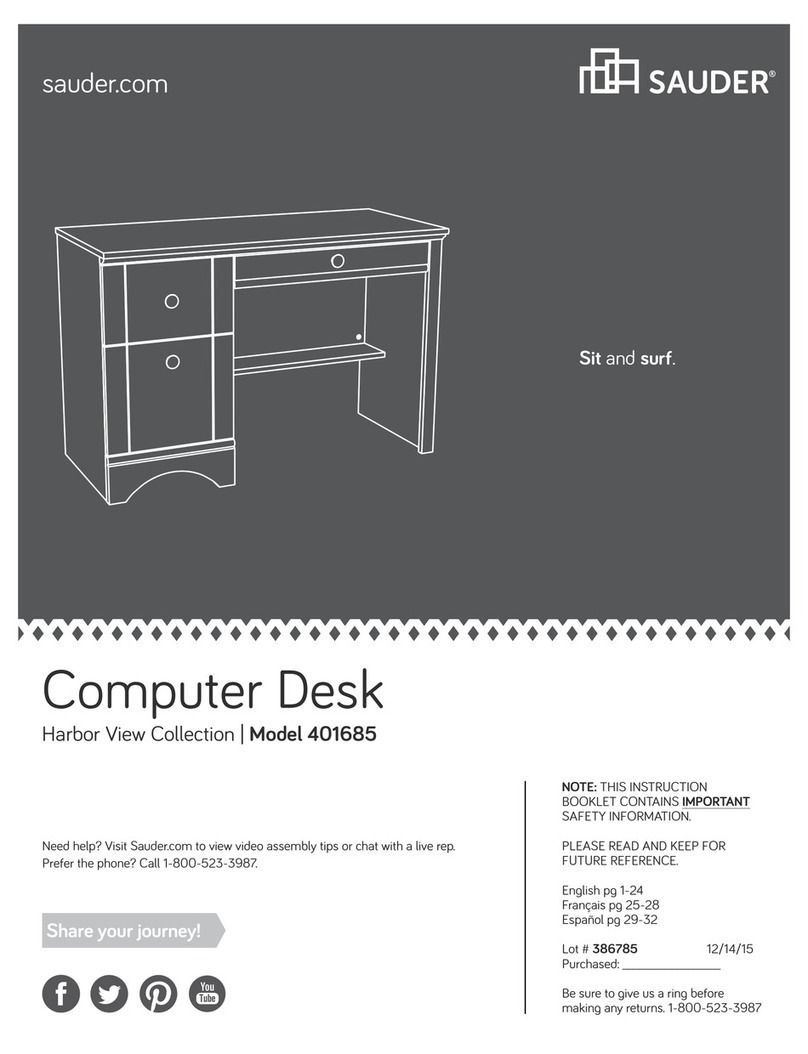
  9. Sauder Tremont Row 427971 User manual

Sauder Tremont Row 427971 User manual

sauder.com
NOTE: THIS INSTRUCTION
BOOKLET CONTAINS IMPORTANT
SAFETY INFORMATION.
PLEASE READ AND KEEP FOR
FUTURE REFERENCE.
sauder.com
CONTACT US FIRST
BEFORE MAKING ANY RETURNS TO THE STORE.
sauder.com
CONTACT US FIRST
BEFORE MAKING ANY RETURNS TO THE RETAILER.
Visit sauder.com/service to order replacement parts, view video assembly tips, or chat with a live rep.
Prefer the phone? Give us a ring at 1-800-445-1527.
Customer Service is available Monday-Friday - 9 a.m. to 5:30 p.m. EST (except holidays)
Sauder.com
Share your journey!
Enlish p 1-22
Français p 23-25
Español p 26-28
Lot # 553606 09/02/20
Purchased: __________________
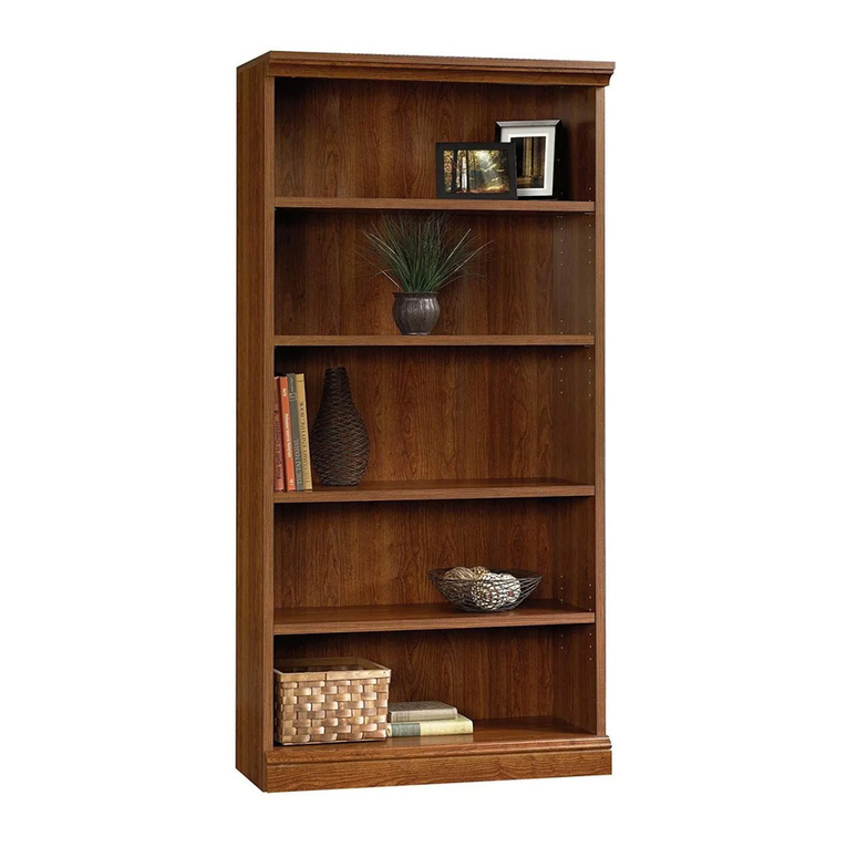
Bookcase
Tremont Row Collection | Model 427971
Deep shelves for
tall tales.
Table of Contents Assembly Tools Required
3
4
5
6-22
23-25
26-28
29-30
31
Part Identification
Hardware Identification
Hardware Usae Guide
Assembly Steps
Français
Español
Safety
Warranty
No. 2 Phillips Screwdriver
Tip Shown Actual Size
Electric drill with
1/8" or 3/8" bit
(ONLY in indicated step)
Pencil
Straiht Ede Screwdriver
Pae 2 www.sauder.com/service 427971
Part Identification
åWhile not all parts are labeled, some of the parts will have a label or an inked letter on the edge
to help distinguish similar parts from each other. Use this part identification to help identify similar parts.
Now you know
our ABCs.
A TOP (1)
B BOTTOM (1)
C LEFT END (1)
D UPRIGHT (1)
E RIGHT END (1)
F BACK (1)
G FIXED SHELF (2)
H MOLDING (2)
J ADJUSTABLE SHELF (2)
K DOOR (1)
L BOTTOM BRACE (2)
M CENTER BRACE (1)
N LOWER FRAME (2)
O UPPER FRAME (2)
A
B
C
D
E
F
G
G
H
H
J
J
K
L
L
M
N
N
O
O
Pae 3www.sauder.com/service427971
Hardware Identification
åScrews are shown actual size. You may receive extra hardware with your unit.
CAM SCREW - 9
2
HIDDEN CAM - 9
1WOOD DOWEL - 12
3PULL - 1
4
METAL PIN - 8
5
L-WRENCH - 1
9
CROSS-SLOTTED
DOWEL - 4
6
1-7/8" HEX HEAD SCREW - 8
12 13 1-3/4" HEX HEAD SCREW - 4
1-9/16" PAN HEAD SCREW - 5
14 1" HEX HEAD SCREW - 6
15
16 1316" MACHINE SCREW  2 1/2" HEX HEAD SCREW - 12
17
1/2" FLAT HEAD SCREW - 8
18 1/2" PAN HEAD SCREW - 14
19
FURNITURE TIPPING
RESTRAINT KIT - 2
96
SMALL APPLIQUE
CARD - 1
7LARGE APPLIQUE
CARD - 1
8
UPPER GUIDE - 2
10 LOWER GUIDE - 2
11
Pae 4 www.sauder.com/service 427971
Hardware Usage Guide
HOW TO USE A HIDDEN CAM & CAM SCREW OR CAM DOWEL
NOTE: Various CAM SCREWS or a CAM DOWEL may be used.
Cam Screws Cam Dowel
Turn the CAM SCREW or
gently tap the CAM DOWEL
until the shoulder is against
the surface of the part.
1.
Hidden Cam
Arrow
Push a HIDDEN CAM into
the part. The arrow in the
HIDDEN CAM must point
toward the hole in the
edge of the board.
Hole
2.
3.
1
2
Insert the CAM SCREW or CAM DOWEL into the
HIDDEN CAM. Tighten the HIDDEN CAM.
Pae 5www.sauder.com/service427971
Step 1
å Assemble your unit on a carpeted floor or on the empty
carton to avoid scratchin your unit or the floor.
å Turn nine CAM SCREWS (2) into the TOP (A) and
LARGE SHELVES (G).
Look for this icon. It means a video assembly tip is
available at www.sauder.com/service/tips
Find the numbered video or scan the QR code.
2
2
A
G
G
1
Pae 6 www.sauder.com/service 427971
StepStep 2
å Insert eiht WOOD DOWELS (3) into the ENDS (C and E)
and UPRIGHT (D).
å Push five HIDDEN CAMS (1) into the ENDS (C and E)
and UPRIGHT (D).
C
D
E
3
1
1
(5 used)
(8 used)
Pae 7www.sauder.com/service427971
Step
å Fasten the ENDS (C and E) and UPRIGHT (D) to
the TOP (A). Tihten five HIDDEN CAMS.
å NOTE: Be sure the WOOD DOWELS in the ENDS and
UPRIGHT insert into the TOP.
Step 3
C
A
D
E
1
Unfinished ede
Surface with HIDDEN CAMS
Surface without HIDDEN CAMS
Do not stand the unit upriht without the
BACK fastened. The unit may collapse.
Caution
Pae 8 www.sauder.com/service 427971
StepStep 4
å Fasten the BOTTOM (B) to the ENDS (C and E) and
UPRIGHT (D). Use five 1-9/16" PAN HEAD SCREWS (14).
å NOTE: Be sure the WOOD DOWELS in the ENDS and
UPRIGHT insert into the BOTTOM.
C
D
E
B
Groove
Unfinished ede
1-9/16" PAN HEAD SCREW
(5 used in this step)
14
14
Pae 9www.sauder.com/service427971
Step
å Fasten the BACK (F) to the TOP (A), BOTTOM (B), and
ENDS (C and E). Use fourteen 1/2" PAN HEAD SCREWS (19).
Step 5
C
A
E
F
B
8
Do not stand the unit upriht without the
BACK fastened. The unit may collapse.
Caution
1/2" PAN HEAD SCREW
(14 used in this step)
19
Pae 10 www.sauder.com/service 427971
StepStep 6
å Fasten the BOTTOM BRACES (L) to the BOTTOM (B).
Tihten four 1/2" HEX HEAD SCREWS (17) usin
the L-WRENCH (9).
å NOTE: Do not completely tihten the SCREWS.
1/2" HEX HEAD SCREW
(4 used in this step)
17
BL
L
9
These tabs should
be facin inward.
Pae 11www.sauder.com/service427971
Step
å Insert two WOOD DOWELS (3) into one of the
MOLDINGS (H).
å Push two HIDDEN CAMS (1) into the MOLDING (H).
å Fasten the MOLDING (H) to one of the FIXED
SHELVES (G). Tihten two HIDDEN CAMS.
å NOTE: Be sure the WOOD DOWELS in the MOLDING
insert into the FIXED SHELF.
å Repeat this step.
Step 7
1
3
G
H
H
Surface with HIDDEN CAMS
1
Pae 12 www.sauder.com/service 427971
StepStep 8
å Fasten one of the LOWER FRAMES (N) to one of the UPPER
FRAMES (O). Tihten four 1/2" HEX HEAD SCREWS (17)
usin the L-WRENCH (9).
å Repeat this step.
N
N
O
O
1/2" HEX HEAD SCREW
(4 used in this step)
17
9
Pae 13www.sauder.com/service427971
Step
å Fasten the FRAMES (N and O) to the FIXED SHELVES (G) and
TOP (A). Tihten eiht 1-7/8" HEX HEAD SCREWS (12) usin
the L-WRENCH (9).
å Fasten the LOWER FRAMES (N) to the BRACES (L and M).
Tihten six 1/2" HEX HEAD SCREWS (17) usin
the L-WRENCH (9).
å NOTE: Do not fully tihten the SCREWS in this step.
Step 9
N
N
O
O
G
G
A
M
L
L
9
1-7/8" HEX HEAD SCREW
(8 used for the SHELVES/TOP)
12
1" HEX HEAD SCREW
(6 used for the BRACES)
15
12
15
Pae 14 www.sauder.com/service 427971
StepStep 10
å Push four CROSS-SLOTTED DOWELS (6) into
the MOLDINGS (H).
å NOTE: The holes in the CROSS-SLOTTED DOWELS
should be pointed towards the holes on the edes
of the MOLDINGS.
å Fasten the UPPER FRAMES (O) to the MOLDINGS (H).
Tihten four 1-3/4" HEX HEAD SCREWS (13) usin
the L-WRENCH (9).
å Fully tihten all of the SCREWS.
6
H
H
1- 3/4" HEX HEAD SCREW
(4 used in this step)
13
13
Pae 15www.sauder.com/service427971
Step
å Open the FURNITURE TIPPING RESTRAINT KITS (96) and fasten
the SAFETY STRAPS to the UPPER FRAMES (O). Use the provided
SHORT SCREW.
å Peel APPLIQUES from the LARGE APPLIQUE CARD (8) and stick
them onto each visible HIDDEN CAM / CROSS-SLOTTED DOWEL.
Step 11
O
O
96
Use the SHORT SCREW
from the RESTRAINT KIT.
Safety strap
8
(2 used)
Pae 16 www.sauder.com/service 427971
StepStep 12
å Fasten the PULL (4) to the DOOR. Use two 13/16"
MACHINE SCREWS (16).
å Fasten the GUIDES (10 and 11) to the DOOR. Use eiht
1/2" FLAT HEAD SCREWS (18).
4
11
10
K
1/2" FLAT HEAD SCREW
(8 used for the GUIDES)
18
18
13/16" MACHINE SCREW
(2 used for the PULL)
16
Pae 17www.sauder.com/service427971
StepStep 13
J
J
D
E
C
å Peel APPLIQUES from the SMALL APPLIQUE CARD (7)
and stick them onto each visible HIDDEN CAM.
å Insert the METAL PINS (5) into the hole locations of your
choice in the ENDS (C and E) and UPRIGHT (D). Set the
ADJUSTABLE SHELVES (J) onto the METAL PINS.
(8 used)
5
5
Pae 18 www.sauder.com/service 427971
Finished ede
7
Step
å Carefully stand your unit upriht in its final location.
å NOTE: The UPPER GUIDE (10) tabs should be down before startin this step.
å Insert the LOWER GUIDES (11) in the DOOR (K) at an anle into the roove in the BOTTOM (B). Then, tilt
the DOOR (K) up vertically. Push the UPPER GUIDE (10) tabs up into the roove in the TOP (A).
å NOTE: The DOOR should slide freely in the track.
å NOTE: The DOOR ap is adjustable. Turn the cam on the LOWER GUIDES (11) with a
STRAIGHT EDGE SCREWDRIVER to adjust the door up or down.
Step 14
The tab should
be down before
you insert it into
the upper track.
The tab should
be up after the
DOOR is in place.
A
A
A
BB
B
KK
K
Turn this
cam to
adjust the
door ap.
11
10
10
Pae 19www.sauder.com/service427971
StepStep 15
å The followin instructions show your unit bein fastened to wall studs. If you are not fastenin your unit to wall studs,
o to the next step now.
å 1st- Locate the center of two studs in your wall near your unit and mark them with a pencil.
å 2nd- Drill a 1/8" hole on each of the marks and into the studs in your wall.
å 3rd-
Fasten the unit to the wall. Use the LONG SCREWS throuh the other end of the SAFETY STRAPS and into
the 1/8" holes.
1st
96
Electric drill with 1/8" bit
3rd
Mark and drill
a 1/8" hole into
the wall stud.
2nd
(2 used)
Pae 20 www.sauder.com/service 427971

Other Sauder Indoor Furnishing manuals

Sauder Shoal Creek 408924 User manual

Sauder

Sauder Shoal Creek 408924 User manual

Sauder Parklane 423107 User manual

Sauder

Sauder Parklane 423107 User manual

Sauder 422290 User manual

Sauder

Sauder 422290 User manual

Sauder Avenue Eight 416513 User manual

Sauder

Sauder Avenue Eight 416513 User manual

Sauder Shoal Creek 409937 User manual

Sauder

Sauder Shoal Creek 409937 User manual

Sauder Pogo 414435 User manual

Sauder

Sauder Pogo 414435 User manual

Sauder Costa 421934 User manual

Sauder

Sauder Costa 421934 User manual

Sauder Palladia Credenza 415025 User manual

Sauder

Sauder Palladia Credenza 415025 User manual

Sauder 420566 User manual

Sauder

Sauder 420566 User manual

Sauder 413854 User manual

Sauder

Sauder 413854 User manual

Sauder Barrister Lane 414723 User manual

Sauder

Sauder Barrister Lane 414723 User manual

Sauder 422294 User manual

Sauder

Sauder 422294 User manual

Sauder 412321 User manual

Sauder

Sauder 412321 User manual

Sauder Primary Street 417932 User manual

Sauder

Sauder Primary Street 417932 User manual

Sauder North Avenue 425190 User manual

Sauder

Sauder North Avenue 425190 User manual

Sauder 415137 User manual

Sauder

Sauder 415137 User manual

Sauder 420612 User manual

Sauder

Sauder 420612 User manual

Sauder 414443 User manual

Sauder

Sauder 414443 User manual

Sauder Lateral File User manual

Sauder

Sauder Lateral File User manual

Sauder Harvey Park Lateral File 426510 User manual

Sauder

Sauder Harvey Park Lateral File 426510 User manual

Sauder Via 419612 User manual

Sauder

Sauder Via 419612 User manual

Sauder Cottage Road 420136 User manual

Sauder

Sauder Cottage Road 420136 User manual

Sauder 418735 User manual

Sauder

Sauder 418735 User manual

Sauder New Grange 422180 User manual

Sauder

Sauder New Grange 422180 User manual

Popular Indoor Furnishing manuals by other brands

Regency LWMS3015 Assembly instructions

Regency

Regency LWMS3015 Assembly instructions

Furniture of America CM7751C Assembly instructions

Furniture of America

Furniture of America CM7751C Assembly instructions

Safavieh Furniture Estella CNS5731 manual

Safavieh Furniture

Safavieh Furniture Estella CNS5731 manual

PLACES OF STYLE Ovalfuss Assembly instruction

PLACES OF STYLE

PLACES OF STYLE Ovalfuss Assembly instruction

Trasman 1138 Bo1 Assembly manual

Trasman

Trasman 1138 Bo1 Assembly manual

Costway JV10856 manual

Costway

Costway JV10856 manual

moss DESIGN Caisson Credenza Assembly instructions

moss DESIGN

moss DESIGN Caisson Credenza Assembly instructions

Aquaglide FULL DECK 15.0 owner's manual

Aquaglide

Aquaglide FULL DECK 15.0 owner's manual

AREBOS AR-HE-SW30 user manual

AREBOS

AREBOS AR-HE-SW30 user manual

Till-Hilft Fulda 87005.330 Assembly instructions

Till-Hilft

Till-Hilft Fulda 87005.330 Assembly instructions

Twoey Outside 2010 quick start guide

Twoey Outside

Twoey Outside 2010 quick start guide

Hettich Easys 200 operating instructions

Hettich

Hettich Easys 200 operating instructions

The bedboss RELAX 404 Series owner's manual

The bedboss

The bedboss RELAX 404 Series owner's manual

Oeseder Möbelindustrie Bern 991 720 Assembly instructions

Oeseder Möbelindustrie

Oeseder Möbelindustrie Bern 991 720 Assembly instructions

Costway HW68469 user manual

Costway

Costway HW68469 user manual

Next ALIX A27743 Assembly instructions

Next

Next ALIX A27743 Assembly instructions

BROSA Hans Assembly guide

BROSA

BROSA Hans Assembly guide

Prodigg MINIKA PBA015T-FUR installation manual

Prodigg

Prodigg MINIKA PBA015T-FUR installation manual

manuals.online logo
manuals.online logoBrands
  • About & Mission
  • Contact us
  • Privacy Policy
  • Terms and Conditions

Copyright 2025 Manuals.Online. All Rights Reserved.