manuals.online logo
Brands
  1. Home
  2. •
  3. Brands
  4. •
  5. Sauder
  6. •
  7. Indoor Furnishing
  8. •
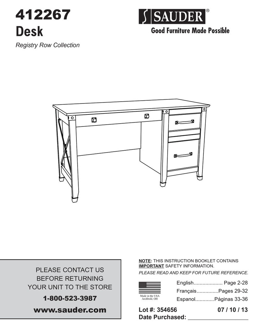
  9. Sauder Avenue Eight 416513 User manual

Sauder Avenue Eight 416513 User manual

NOTE: THIS INSTRUCTION
BOOKLET CONTAINS IMPORTANT
SAFETY INFORMATION.
PLEASE READ AND KEEP FOR
FUTURE REFERENCE.
English pg 1-40
Français pg 41-46
Español pg 47-52
Lot # 398173 11/23/16
Purchased: __________________
Be sure to give us a ring before
making any returns. 1-800-523-3987
Executive Desk
Avenue Eight Collection | Model 416513
Need help? Visit Sauder.com to view video assembly tips or chat with a live rep.
Prefer the phone? Call 1-800-523-3987.
Share your journey!
sauder.com
Get executive
with this decision.
Table of Contents Assembly Tools Required
2-4
5-7
8-40
41-46
47-52
53-54
55
Part Identification
Hardware Identification
Assembly Steps
Français
Español
Safety
Warranty
Hammer
Not actual size
No. 2 Phillips Screwdriver
Tip Shown Actual Size
Skip the power trip.
This time.
416513 www.sauder.com/servicesPage 2
Part Identification
åWhile not all parts are labeled, some of the parts will have a label or an inked letter on the edge
to help distinguish similar parts from each other. Use this part identification to help identify similar parts.
A OUTER END (2)
B3 RIGHT END (1)
C3 LEFT END (1)
D2 RIGHT UPRIGHT (1)
D32 LARGE LEFT DRAWER SIDE (2)
D33 LARGE RIGHT DRAWER SIDE (2)
D34 SMALL RIGHT DRAWER SIDE (2)
D35 SMALL LEFT DRAWER SIDE (2)
D36 RIGHT DRAWER SIDE (2)
D37 LEFT DRAWER SIDE (2)
D74 SMALL DRAWER BACK (2)
D77 DRAWER BACK (2)
D78 LARGE DRAWER BACK (2)
D708 LARGE DRAWER BOTTOM (2)
D716 DRAWER BOTTOM (4)
E2 LEFT UPRIGHT (1)
F2 TOP (1)
G2 BOTTOM (2)
H2 MODESTY PANEL (1)
I BACK (1)
J PEDESTAL BACK (1)
K BRACE (4)
L DOOR (1)
M ADJUSTABLE SHELF (1)
M35 MOLDING (4)
N SKIRT (4)
O KEYBOARD FRONT (1)
P KEYBOARD BACK (1)
Q KEYBOARD SIDE (2)
R KEYBOARD SHELF (1)
S LARGE DRAWER BOX FRONT (2)
T LARGE RIGHT DRAWER FRONT (1)
U LARGE LEFT DRAWER FRONT (1)
Z DRAWER BOX FRONT (2)
AA RIGHT DRAWER FRONT (1)
BB LEFT DRAWER FRONT (1)
DD PLINTH (8)
FF SMALL RIGHT DRAWER FRONT (1)
GG SMALL LEFT DRAWER FRONT (1)
LL TOP REAR MOLDING (1)
MM UPPER BACK MOLDING (1)
NN SIDE MOLDING (2)
OO LOWER MOLDING (1)
PP UPPER MOLDING (1)
RR LEFT BOTTOM MOLDING (2)
TT RIGHT BOTTOM MOLDING (2)
UU TOP FRONT MOLDING (1)
VV HALF DISK (8)
Part Identification Now you know
our ABCs.
416513www.sauder.com/services Page 3
A
B3
C3
D2
E2
F2
G2
H2
I
J
K
L
M
N
DD
LL
MM
NN
OO
M35
RR
UU
A
G2
K
K
K
N
N
N
DD
DD
DD
DD
DD
PP
NN
M35
M35
M35
DD
TT
RR
VV
VV
DD
TT
VV
VV
Part Identification Now you know
our ABCs.
416513 www.sauder.com/servicesPage 4
O
PQ
R
Q
ST
US
Z
AA
BB
Z
FF
GG
D716
D716
D716
D716
D708
D708
D78 D33
D32
D37
D36
D77
D35
D34
D74
D32
D78 D33
D37
D77 D36
D34
D35
D74
Hardware Identification
åScrews are shown actual size. You may receive extra hardware with your unit.
416513www.sauder.com/services Page 5
(EXTENSION SET SHOWN SEPARATED)
NARROW
EXTENSION RAIL - 8
AAA NARROW
EXTENSION SLIDE - 8
BBB
WIDE
EXTENSION SLIDE - 4
DDD
WIDE
EXTENSION RAIL - 4
CCC
ZZ LEFT DRAWER SLIDE - 1
RIGHT CABINET RAIL - 1
WW LEFT CABINET RAIL - 1
XX RIGHT DRAWER SLIDE - 1
YY
FILE GLIDE - 4
6B FILE ROD - 4
8B
HIDDEN CAM - 8
1F CAM DOWEL - 8
2F 7F TWIST-LOCK®FASTENER - 25
Hardware Identification
åScrews are shown actual size. You may receive extra hardware with your unit.
416513 www.sauder.com/servicesPage 6
19G METAL BRACKET - 2
KNOB - 8
42K
SMALL DRAWER
FRONT BRACKET - 2
6G DRAWER FRONT
BRACKET - 2
9G
LARGE DRAWER
FRONT BRACKET - 4
10G ANGLE BRACKET - 40
27G
MOLDING
CONNECTOR - 4
17F
KEYBOARD HINGE - 2
12H
FELT DISC CARD - 1
1M GROMMET CAP - 2
1P CORD CLIP - 1
9P
GROMMET - 3
10P METAL PIN - 12
1R RUBBER SLEEVE - 4
2R
14H HINGE - 2
Hardware Identification
åScrews are shown actual size. You may receive extra hardware with your unit.
416513www.sauder.com/services Page 7
BLACK 7/8" MACHINE SCREW - 4
37S
BLACK 1-1/8" PAN HEAD SCREW - 16
9S
BLACK 9/16" LARGE HEAD SCREW - 106
1S
BLACK 1-1/4" FLAT HEAD SCREW - 46
7S
SILVER 1-1/4" MACHINE SCREW - 4
35S
18S BROWN 1" FLAT HEAD SCREW - 12
3S GOLD 5/16" FLAT HEAD SCREW - 48
SILVER 5/8" FLAT HEAD SCREW - 4
23S
SILVER 9/16" LARGE HEAD SCREW - 2
54S 100S BLACK 2-3/4" FLAT HEAD SCREW - 3
BLACK 1/2" FLAT HEAD SCREW - 4
11S
30S BLACK 1-9/16" FLAT HEAD SCREW - 24
BLACK 1-15/16" FLAT HEAD SCREW - 8
113S
Step 1 Look for this icon. It means a
video assembly tip is available at
www.sauder.com/services/tips
å Assemble your unit on a carpeted floor or on the empty
carton to avoid scratching your unit or the floor.
å To begin assembly, push a SAUDER TWIST-LOCK®
FASTENER (7F) into the large holes in the OUTER ENDS (A).
å Repeat this step for the ENDS (B3 and C3), UPRIGHTS (D2
and E2), BOTTOMS (G2), MODESTY PANEL (H2), and UPPER
BACK MOLDING (MM).
416513 www.sauder.com/servicesPage 8
A
A
(25 used)
Do not tighten the TWIST-LOCK® FASTENERS in this step.
7F
Scan this QR code or go to this address:
http://qr.sauder.com/?ID=1659
to watch a video on how to assemble your unit.
å Push eight HIDDEN CAMS (1F) into the BOTTOMS (G2).
Then, insert the metal end of a CAM DOWEL (2F) into
each HIDDEN CAM.
Step 2
416513www.sauder.com/services Page 9
G2
G2
(8 used)
Arrow
Insert the metal end of the CAM
DOWEL into the HIDDEN CAM.
Arrow
Do not tighten the HIDDEN CAMS in this step.
2F
1F
Step 3
å NOTE: Before beginning this step, separate the NARROW EXTENSION
SETS (AAA and BBB) from the WIDE EXTENSION SETS (CCC and DDD).
Do not confuse these SETS once they are separated.
å Separate the NARROW EXTENSION SLIDES (BBB) from the NARROW EXTENSION
RAILS (AAA) as shown in the upper diagram below. Be prepared, the parts are greasy.
å Fasten the NARROW EXTENSION RAILS (AAA) to the ENDS (B3 and C3) and
UPRIGHTS (D2 and E2). Use sixteen GOLD 5/16" FLAT HEAD SCREWS (3S).
å NOTE: For each EXTENSION RAIL, turn a SCREW into the hole shown in the enlarged
diagram. Then, slide the inner cartridge of the EXTENSION RAIL in to find the other
hole that lines up with the hole in the END and UPRIGHT. Turn a SCREW into this hole.
å NOTE: The EXTENSION SLIDES will be used later for the DRAWERS.
416513 www.sauder.com/servicesPage 10
C3
B3
D2
E2
AAA
AAA
AAA
AAA
AAA
AAA
AAA
AAA
Push the release lever in and pull the SLIDE from the RAIL.
AAABBB
Narrow
Extension
Rails
Open end
Open end
Open end
Open end
Narrow
Extension
Rails
Surface with
TWIST-LOCK®
FASTENERS
Surface with
TWIST-LOCK®
FASTENERS
Surface with
TWIST-LOCK®
FASTENERS
Surface with
TWIST-LOCK®
FASTENERS
GOLD 5/16" FLAT HEAD SCREW
(16 used in this step)
3S
å Separate the WIDE EXTENSION SLIDES (DDD) from the WIDE EXTENSION RAILS (CCC) as shown in the upper diagram
below. Be prepared, the parts are greasy.
å Fasten the WIDE EXTENSION RAILS (CCC) to the ENDS (B3 and C3) and UPRIGHTS (D2 and E2). Use twelve GOLD
5/16" FLAT HEAD SCREWS (3S).
å NOTE: For each EXTENSION RAIL, turn a SCREW into the hole shown in the enlarged diagram. Then, slide the inner
cartridge of the EXTENSION RAIL in to find the other holes that line up with the holes in the ENDS and UPRIGHTS. Turn a
SCREW into this hole.
å NOTE: The EXTENSION SLIDES will be used later for the DRAWERS.
å Fasten four ANGLE BRACKETS (27G) to the RIGHT END (B3) and RIGHT UPRIGHT (D2). Use four BLACK 9/16" LARGE
HEAD SCREWS (1S).
å NOTE: Be sure the edges
of the ANGLE BRACKETS
are even with the edges of
the END and UPRIGHT.
Step 4
416513www.sauder.com/services Page 11
C3
B3
D2
E2
CCC
CCC
CCC
CCC
Push the black lever in and pull the SLIDE from the RAIL.
CCCDDD
Wide
Extension
Rails
Wide
Extension
Rails
Open end
Open end
Open end
Open end
(4 used)
GOLD 5/16" FLAT HEAD SCREW
(12 used in this step)
3S
BLACK 9/16" LARGE HEAD SCREW
(4 used for the ANGLE BRACKETS)
1S
27G
27G
Step 5
å Fasten the CABINET RAILS (WW and XX) to the other
surfaces of the UPRIGHTS (D2 and E2). Use four GOLD
5/16" FLAT HEAD SCREWS (3S).
å NOTE: The CABINET RAILS are marked "CABINET
RIGHT" and "CABINET LEFT" for easy identification.
416513 www.sauder.com/servicesPage 12
D2
E2
WW
XX
Surface without
TWIST-LOCK
®
FASTENERS
Surface without
TWIST-LOCK
®
FASTENERS
Roller end
These holes must be here.
Roller end
GOLD 5/16" FLAT HEAD SCREW
(4 used in this step)
3S
å Tap four MOLDING CONNECTORS (17F) into the notches
in the TOP MOLDINGS (LL and UU) and
SIDE MOLDINGS (NN).
Step 6
416513www.sauder.com/services Page 13
LL
NN
UU
NN
Flat end Flat end
Use your hammer to tap the MOLDING CONNECTORS (17F) into the notches in the MOLDINGS.
17F
17F
Step 7
å Fasten the TOP MOLDINGS (LL and UU) and SIDE
MOLDINGS (NN) to the TOP (F2). Use sixteen BLACK
1-1/4" FLAT HEAD SCREWS (7S).
416513 www.sauder.com/servicesPage 14
LL
NN
UU
NN
F2
Surface with holes
The large holes must be here.
The TOP REAR
MOLDING (LL)
has more holes.
BLACK 1-1/4" FLAT HEAD SCREW
(16 used in this step)
7S
å Fasten the METAL BRACKETS (19G) to the UPPER
BACK MOLDING (MM). Use two BLACK 9/16" LARGE
HEAD SCREWS (1S).
å Fasten the UPPER BACK MOLDING (MM) to the TOP
REAR MOLDING (LL) on the TOP (F2). Tighten three
TWIST-LOCK® FASTENERS.
Step 8
416513www.sauder.com/services Page 15
LL
F2
MM
How to use the SAUDER TWIST-LOCK®FASTENER
1. Insert the dowel end of the FASTENER into the
hole of the adjoining part.
NOTE: The dowel end of the FASTENER must
remain fully inserted in the hole of the adjoining
part while locking the FASTENER.
2. Tighten the FASTENER with a Phillips
screwdriver as tight as possible.
Edge and surface with
TWIST-LOCK® FASTENERS
MM
Dowel end
BLACK 9/16" LARGE HEAD SCREW
(2 used in this step)
1S
19G
19G
Step 9
å Fasten the HALF DISKS (VV) to the PLINTHS (DD). Use
eight BROWN 1" FLAT HEAD SCREWS (18S).
å Fasten twenty ANGLE BRACKETS (27G) to the
OUTER ENDS (A). Use twenty BLACK 9/16" LARGE
HEAD SCREWS (1S).
å NOTE: Be sure the edges of the ANGLE BRACKETS are
even with the edges of the OUTER ENDS.
416513 www.sauder.com/servicesPage 16
DD
VV
A
A
DD
VV
DD
VV
DD
VV
DD
VV
DD
VV
DD
VV
DD
VV
The larger hole
should be facing up.
Surface with
TWIST-LOCK
®
FASTENERS
Surface with
TWIST-LOCK
®
FASTENERS
(20 used)
BLACK 9/16" LARGE HEAD SCREW
(20 used for the ANGLE BRACKETS)
1S
27G
27G
BROWN 1" FLAT HEAD SCREW
(8 used in this step)
18S
å Fasten the OUTER ENDS (A) to the SIDE
MOLDINGS (NN) on the TOP (F2). Tighten four
TWIST-LOCK® FASTENERS.
Step 10
416513www.sauder.com/services Page 17
A
A
NN
F2
NN
Surface with
TWIST-LOCK®
FASTENERS
Surface without
TWIST-LOCK®
FASTENERS
Step 11
å Fasten the PLINTHS (DD) and MOLDINGS (M35) to
the OUTER ENDS (A). Use twenty BLACK 9/16" LARGE
HEAD SCREWS (1S).
416513 www.sauder.com/servicesPage 18
A
A
DD
DD
DD
DD
VV
VV
VV
Use outer holes.
VV
The MOLDING (M35) should be
centered over the HALF DISK (VV).
These holes
must be here.
These holes
must be here.
Use outer holes.
Use outer holes.
Use outer holes.
M35
M35
M35
M35
BLACK 9/16" LARGE HEAD SCREW
(20 used for the ANGLE BRACKETS)
1S
Step 12
416513www.sauder.com/services Page 19
F2
C3
B3
Surface with
TWIST-LOCK®
FASTENERS
Surface without
TWIST-LOCK®
FASTENERS
Open end
Open end
(4 used)
1R
å Insert four METAL PINS (1R) into the ENDS (B3 and C3).
å Fasten the ENDS (B3 and C3) to the TOP (F2). Tighten
four TWIST-LOCK® FASTENERS.
å NOTE: Be sure the METAL PINS in the ENDS insert into
the holes in the TOP.
Step 13
å Fasten the BOTTOMS (G2) to the OUTER ENDS (A). Tighten
four TWIST-LOCK® FASTENERS.
å Fasten the BOTTOMS (G2) to the ENDS (B3 and C3). Use
four BLACK 1-15/16" FLAT HEAD SCREWS (113S).
å Insert four METAL PINS (1R) into the PEDESTAL BACK (J).
å Insert the METAL PINS (1R) in one end of the PEDESTAL
BACK (J) into the holes in the LEFT END (C3).
416513 www.sauder.com/servicesPage 20
Surface with
TWIST-LOCK
®
FASTENERS
Surface with
TWIST-LOCK
®
FASTENERS
A
A
JC3
G2
G2
B3
The large holes must be here.
Unfinished
surface
(4 used)
1R
113S
BLACK 1-15/16" FLAT HEAD SCREW
(4 used in this step)
113S

Other Sauder Indoor Furnishing manuals

Sauder Carson Forge 416969 User manual

Sauder

Sauder Carson Forge 416969 User manual

Sauder Storage Cabinet 419496 User manual

Sauder

Sauder Storage Cabinet 419496 User manual

Sauder 408995 User manual

Sauder

Sauder 408995 User manual

Sauder 422294 User manual

Sauder

Sauder 422294 User manual

Sauder Rollingwood 431407 User manual

Sauder

Sauder Rollingwood 431407 User manual

Sauder Entertainment Credenza 403891 User manual

Sauder

Sauder Entertainment Credenza 403891 User manual

Sauder Lateral File 107302 User manual

Sauder

Sauder Lateral File 107302 User manual

Sauder 535782 User manual

Sauder

Sauder 535782 User manual

Sauder 430083 User manual

Sauder

Sauder 430083 User manual

Sauder Harbor View 420471 User manual

Sauder

Sauder Harbor View 420471 User manual

Sauder Harbor View 417587 User manual

Sauder

Sauder Harbor View 417587 User manual

Sauder Cannery Bridge 429512 User manual

Sauder

Sauder Cannery Bridge 429512 User manual

Sauder Orchard Hills 418650 User manual

Sauder

Sauder Orchard Hills 418650 User manual

Sauder Lateral File 419606 User manual

Sauder

Sauder Lateral File 419606 User manual

Sauder 402375 User manual

Sauder

Sauder 402375 User manual

Sauder Soft Modern 415007 User manual

Sauder

Sauder Soft Modern 415007 User manual

Sauder Worksense MASON PEAK 427827 User manual

Sauder

Sauder Worksense MASON PEAK 427827 User manual

Sauder Harbor View 403680 User manual

Sauder

Sauder Harbor View 403680 User manual

Sauder County Line 415995 User manual

Sauder

Sauder County Line 415995 User manual

Sauder Edge Water 409047 User manual

Sauder

Sauder Edge Water 409047 User manual

Sauder 411802 User manual

Sauder

Sauder 411802 User manual

Sauder Shoal Creek 408750 User manual

Sauder

Sauder Shoal Creek 408750 User manual

Sauder Pogo 417146 User manual

Sauder

Sauder Pogo 417146 User manual
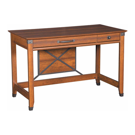
Sauder OFFICE WORKS AFFIRM 426466 User manual

Sauder

Sauder OFFICE WORKS AFFIRM 426466 User manual

Popular Indoor Furnishing manuals by other brands

Lightolier Luminaire Instructions for installation

Lightolier

Lightolier Luminaire Instructions for installation

Opus LIT 140 Assembly instruction

Opus

Opus LIT 140 Assembly instruction

Triarch 32773 Assembly instructions

Triarch

Triarch 32773 Assembly instructions

Grain Montauk MT0520 Assembly instructions

Grain

Grain Montauk MT0520 Assembly instructions

Next 290242 Assembly instructions

Next

Next 290242 Assembly instructions

PALI NOVARA Assembly instructions

PALI

PALI NOVARA Assembly instructions

Intel EVO UA210021-GG installation guide

Intel

Intel EVO UA210021-GG installation guide

Flexsteel home W1347-730 manual

Flexsteel home

Flexsteel home W1347-730 manual

nbf Signature NBF-GTT7230WH Assembly instructions

nbf

nbf Signature NBF-GTT7230WH Assembly instructions

WLIVE ABZ003 quick start guide

WLIVE

WLIVE ABZ003 quick start guide

MAGAZIN SCHRANK P100 manual

MAGAZIN

MAGAZIN SCHRANK P100 manual

&Tradition Column JA1 instructions

&Tradition

&Tradition Column JA1 instructions

JWA CLEMENTINE 70186 Assembly instruction

JWA

JWA CLEMENTINE 70186 Assembly instruction

Kvik MO820 manual

Kvik

Kvik MO820 manual

Kinfine HOMEPOP K6699 Assembly instructions

Kinfine

Kinfine HOMEPOP K6699 Assembly instructions

Core Products Augusta AG902 Assembly instructions

Core Products

Core Products Augusta AG902 Assembly instructions

BRW ROKSANA 2 SZF3D/22/18 Assembly instructions

BRW

BRW ROKSANA 2 SZF3D/22/18 Assembly instructions

Rauch M2106 Assembly instructions

Rauch

Rauch M2106 Assembly instructions

manuals.online logo
manuals.online logoBrands
  • About & Mission
  • Contact us
  • Privacy Policy
  • Terms and Conditions

Copyright 2025 Manuals.Online. All Rights Reserved.