manuals.online logo
Brands
  1. Home
  2. •
  3. Brands
  4. •
  5. Sauder
  6. •
  7. Indoor Furnishing
  8. •
  9. Sauder Shoal Creek 420166 User manual

Sauder Shoal Creek 420166 User manual

NOTE: THIS INSTRUCTION
BOOKLET CONTAINS IMPORTANT
SAFETY INFORMATION.
PLEASE READ AND KEEP FOR
FUTURE REFERENCE.
Enlish p 1-32
Français p 33-36
Español p 37-40
Lot # 516039 03/29/18
Purchased: __________________
Be sure to ive us a rin before
makin any returns. 1-800-523-3987
Need help? Visit Sauder.com to view video assembly tips or chat with a live rep.
Prefer the phone? Call 1-800-523-3987.
Share your journey!
sauder.com
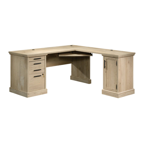
Computer Desk
Shoal Creek Collection | Model 420166
Sit and surf.
Table of Contents Assembly Tools Required
2-3
4-5
6-32
33-36
37-40
41-42
43
Part Identification
Hardware Identification
Assembly Steps
Français
Español
Safety
Warranty
Hammer
Not actual size
No. 2 Phillips Screwdriver
Tip Shown Actual Size
Skip the power trip.
This time.
420166 www.sauder.com/servicesPae 2
Part Identification
åWhile not all parts are labeled, some of the parts will have a label or an inked letter on the ede
to help distinuish similar parts from each other. Use this part identification to help identify similar parts.
A RIGHT END (1)
B LEFT END (1)
C RIGHT UPRIGHT (1)
D LEFT UPRIGHT (1)
D28 LARGE RIGHT DRAWER SIDE (1)
D29 LARGE LEFT DRAWER SIDE (1)
D30 RIGHT DRAWER SIDE (1)
D31 LEFT DRAWER SIDE (1)
D77 DRAWER BACK (1)
D78 LARGE DRAWER BACK (1)
D427 PENCIL RIGHT DRAWER SIDE (1)
D428 PENCIL LEFT DRAWER SIDE (1)
D502 PENCIL DRAWER BACK (1)
D503 PENCIL DRAWER BOX FRONT (1)
D504 PENCIL DRAWER BOTTOM (1)
D707 LARGE DRAWER BOTTOM (1)
D716 DRAWER BOTTOM (1)
E TOP (1)
F RIGHT BOTTOM (1)
G LEFT BOTTOM (1)
H MODESTY PANEL (1)
I DOOR (1)
J ADJUSTABLE SHELF (1)
K RIGHT FRONT/LEFT REAR LEG (2)
L LEFT FRONT/RIGHT REAR LEG (2)
M DRAWER FRONT (1)
M65 PENCIL DRAWER BRACE (1)
N LARGE DRAWER FRONT (1)
O PENCIL DRAWER FRONT (1)
P END MOLDING (2)
Part Identification Now you know
our ABCs.
420166www.sauder.com/services Pae 3
A
B
C
D
E
F
G
H
I
J
K
L
M
N
O
P
P
K
LD77
D31
D716
D30
D78
D29
D707
D28
D502
D428
D504
D427
D503
M65
Hardware Identification
420166 www.sauder.com/servicesPae 4
FILE ROD - 2
8B
40CA CABINET RIGHT - 1 40CB CABINET LEFT - 1 40CC DRAWER RIGHT - 1 40CD DRAWER LEFT - 1
FILE GLIDE - 2
15B
10A SLIDE CAM - 4 22A SPACER - 2
TURNBUCKLE - 1
9A
HIDDEN
CAM - 35
1F
CAM DOWEL - 23
2F 7F TWIST-LOCK®
FASTENER - 8 CAM SCREW - 12
8F WOOD
DOWEL - 8
15F ANCHOR PLATE - 2
66G
LONG SUPPORT ROD - 1
23A
SHORT SUPPORT ROD - 1
28A
(EXTENSION SET SHOWN SEPARATED)
EXTENSION SLIDE - 2
40MC
EXTENSION RAIL - 2
40MA
(EXTENSION SET SHOWN SEPARATED)
EXTENSION SLIDE - 2
40NC
EXTENSION RAIL - 2
40NA
Hardware Identification
åScrews are shown actual size. You may receive extra hardware with your unit.
420166www.sauder.com/services Pae 5
BLACK 9/16" LARGE HEAD SCREW - 8
1S 3S GOLD 5/16" FLAT HEAD SCREW - 24
BLACK 7/8" LARGE HEAD SCREW - 2
17S SILVER 3/4" MACHINE SCREW - 6
20S
SILVER 5/8" FLAT HEAD SCREW - 4
23S 30S BLACK 1-9/16" FLAT HEAD SCREW - 13
BLACK 9/16" FLAT HEAD SCREW - 6
32S SILVER 1-1/2" MACHINE SCREW - 2
95S
14H HINGE - 2
22H
HINGE SPACER - 2 DOOR STOP - 1
4I PULL - 3
7K KNOB - 2
24K
GROMMET CAP - 1
1P GROMMET - 3
10P CAM COVER - 3
13P METAL PIN - 4
1R
Step 1 Look for this icon. It means a
video assembly tip is available at
www.sauder.com/services/tips
å NOTE: You may need someone's help while assemblin this unit.
å Assemble your unit on a carpeted floor or on the empty carton to
avoid scratchin your unit or the floor.
å Push twenty-three HIDDEN CAMS (1F) into the UPRIGHTS (C
and D), BOTTOMS (F and G), MODESTY PANEL (H), and PENCIL
DRAWER BRACE (M65). Then, insert the metal end of a CAM
DOWEL (2F) into each HIDDEN CAM.
420166 www.sauder.com/servicesPae 6
(23 used)
Arrow
1F
2F
Do not tihten the HIDDEN CAMS in this step.
Insert the metal end of the CAM
DOWEL into the HIDDEN CAM.
Arrow
F
G
H
M65
C
D
1F
2F
Arrow
Arrow
1F
2F
å Push twelve HIDDEN CAMS (1F) into the ENDS (A and B).
å Turn twelve CAM SCREWS (8F) into the LEGS (K and L).
å NOTE: Use the exact holes shown.
Step 2
420166www.sauder.com/services Pae 7
Arrow
Arrow
1F
The arrow in the HIDDEN
CAM must point toward the
hole in the ede of the board.
Hole (12 used)
1F
Arrow
B
A
8F
(12 used)
L
L
K
K
Step 3
å Insert four WOOD DOWELS (15F) into two of
the LEGS (K and L).
å Fasten the ENDS (A and B) to the LEGS (K and L). Tihten
six HIDDEN CAMS.
å NOTE: Be sure the WOOD DOWELS in the LEGS insert
into the holes in the ENDS.
420166 www.sauder.com/servicesPae 8
15F
1
2
B
A
These surfaces
should be even.
Surface with HIDDEN CAMS
These lare
holes must
be here.
Surface with HIDDEN CAMS
These lare
holes must
be here.
L
K
15F
These surfaces
should be even.
Anled ede
Anled ede
å Turn six BLACK 9/16" FLAT HEAD SCREWS (32S) into
the ENDS (A and B) until the shoulders of the SCREWS
rest on the surfaces of the ENDS.
å NOTE: Do not overtihten the SCREWS.
å Slide the END MOLDINGS (P) onto the ENDS (A and B).
Line up the rooves in the MOLDINGS over the heads of
the SCREWS in the ENDS.
å NOTE: If the MOLDING comes up o of the SCREWS,
remove it and slide it on aain.
Step 4
420166www.sauder.com/services Pae 9
These edes
should be even.
BLACK 9/16" FLAT HEAD SCREW
(6 used in this step)
32S
B
A
P
P
Shoulder
Shoulder
Apply pressure with your hands
as you uide the MOLDINGS over
the SCREWS and onto the ENDS.
Apply pressure with your hands
as you uide the MOLDINGS over
the SCREWS and onto the ENDS.
These edes
should be even.
32S
Surface without
HIDDEN CAMS
Surface without
HIDDEN CAMS
Step 5
420166 www.sauder.com/servicesPae 10
å Insert four WOOD DOWELS (15F) into the remainin
two LEGS (K and L).
å Fasten the LEGS (K and L) to the ENDS (A and B). Tihten
six HIDDEN CAMS.
å NOTE: Be sure the WOOD DOWELS in the LEGS insert
into the holes in the ENDS.
15F
B
A
These surfaces
should be even.
Surface with HIDDEN CAMS
These lare
holes must
be here.
Surface with HIDDEN CAMS
These lare
holes must
be here.
L
K
15F
These surfaces
should be even.
Anled ede
Anled ede
Some assembly
(and snacks) required.
å Separate the EXTENSION SLIDES (40MC) from the EXTENSION RAILS (40MA) as shown in the upper diaram below. Be
prepared, the parts are reasy.
å Fasten the EXTENSION RAILS (40MA) to the RIGHT END (A) and RIGHT UPRIGHT (C). Use four GOLD 5/16" FLAT HEAD
SCREWS (3S) throuh holes #1 and #4.
å NOTE: For each EXTENSION RAIL, turn a SCREW into the hole shown in the enlared diaram. Then, slide the inner
cartride of the EXTENSION RAIL in to find the other holes that line up with the holes in the END and UPRIGHT. Turn a
SCREW into this hole.
å NOTE: The EXTENSION SLIDES will be used later for the LARGE DRAWER.
Step 6
420166www.sauder.com/services Pae 11
C
A
Open end
Open end
GOLD 5/16" FLAT HEAD SCREW
(4 used in this step)
3S
These lare
holes must
be here.
This lare
hole must
be here.
Surface with
HIDDEN CAMS
Push the black lever in and pull the SLIDE from the RAIL.
40MA40MC
1
2
34
1
2
3
4
Step 7
å Fasten the CABINET RIGHT (40CA) to the RIGHT
END (A) and the CABINET LEFT (40CB) to the RIGHT
UPRIGHT (C). Use four GOLD 5/16" FLAT HEAD
SCREWS (3S) throuh holes #1 and #3.
420166 www.sauder.com/servicesPae 12
GOLD 5/16" FLAT HEAD SCREW
(4 used in this step)
3S
1
2
3
4
1
2
3
4
Roller end
Roller end
C
A
These lare
holes must
be here.
This lare
hole must
be here.
å Separate the EXTENSION SLIDES (40NC) from the EXTENSION RAILS (40NA) as shown in the upper diaram
below. Be prepared, the parts are reasy.
å Fasten the EXTENSION RAILS (40NA) to the UPRIGHTS (C and D). Use four GOLD 5/16" FLAT HEAD SCREWS (3S)
throuh holes #1 and #4.
å NOTE: For each EXTENSION RAIL, turn a SCREW into the hole shown in the enlared diaram. Then, slide the inner
cartride of the EXTENSION RAIL in to find the other holes that line up with the holes in the UPRIGHTS. Turn a
SCREW into this hole.
å NOTE: The EXTENSION SLIDES will be used later for the PENCIL DRAWER.
Step 8
420166www.sauder.com/services Pae 13
Open end
GOLD 5/16" FLAT HEAD SCREW
(4 used in this step)
3S
D
C
Open end
1
2
3
4
1
2
3
4
Surface without
HIDDEN CAMS
Surface without
HIDDEN CAMS
This lare
hole must
be here.
This lare
hole must
be here.
Push the black lever in and pull the SLIDE from the RAIL.
40NA40NC
Step 9
å Fasten the ANCHOR PLATES (66G) to the TOP (E)
exactly as shown. Use eiht BLACK 9/16" LARGE
HEAD SCREWS (1S).
420166 www.sauder.com/servicesPae 14
BLACK 9/16" LARGE HEAD SCREW
(8 used in this step)
1S
Unfinished surface
This lare hole
must be here.
E
66G
66G
å Fasten the UPRIGHTS (C and D) to the TOP (E). Tihten
four HIDDEN CAMS.
Step 10
420166www.sauder.com/services Pae 15
Start Tighten
Arrow
Minimum
190 derees
Caution
Risk of damae or
injury. HIDDEN CAMS
must be completely
tihtened. HIDDEN
CAMS that are not
completely tihtened
may loosen, and parts
may separate. To
completely tihten:
Arrow
Maximum
210 derees
E
Surface without
HIDDEN CAMS
C
Surface with
HIDDEN CAMS
D
Curved ede
W
This lare
hole must
be here.
Now miht be a
ood time to refresh
your drink.
Step 11
å NOTE: You may need someone's help in this step.
å Insert the dowel ends of four SAUDER TWIST-LOCK®
FASTENERS (7F) into the TOP (E).
å Push the MODESTY PANEL (H) onto the four TWIST-LOCK®
FASTENERS in the TOP (E).
å Fasten the MODESTY PANEL (H) to the TOP (E). Tihten four
TWIST-LOCK® FASTENERS.
å Fasten the MODESTY PANEL (H) to the UPRIGHTS (C and D).
Tihten four HIDDEN CAMS.
å Insert two GROMMETS (10P) into the lare holes in the
MODESTY PANEL (H).
420166 www.sauder.com/servicesPae 16
7F
E
E
Surface with
HIDDEN CAMS
Dowel end
D
C
H
Arrow
Minimum
190 derees
Maximum
210 derees
10P
Flat ede
H
How to use the SAUDER TWIST-LOCK®FASTENER
1. Tihten the FASTENER with a Phillips screwdriver
as tiht as possible.
NOTE: The dowel end of the FASTENER must
remain fully inserted in the hole of the adjoinin part
while lockin the FASTENER.
å Fasten the BOTTOMS (F and G) to the UPRIGHTS (C
and D). Tihten four HIDDEN CAMS.
Step 12
420166www.sauder.com/services Pae 17
Arrow
Minimum
190 derees
Maximum
210 derees
D
C
G
F
Surface with
HIDDEN CAMS
Surface
with
HIDDEN
CAMS
Finished ede
Finished ede
Step 13
420166 www.sauder.com/servicesPae 18
Arrow
Minimum
190 derees
Maximum
210 derees
å Insert the dowel ends of four SAUDER TWIST-LOCK®
FASTENERS (7F) into the TOP (E).
å Push the ENDS (A and B) onto the four TWIST-LOCK®
FASTENERS in the TOP (E).
å Fasten the ENDS (A and B) to the TOP (E). Tihten four
TWIST-LOCK® FASTENERS.
å Fasten the ENDS (A and B) to the BOTTOMS (F and G) and
MODESTY PANEL (H). Tihten ten HIDDEN CAMS.
7F
E
Dowel end
D
CH
B
A
G
F
7F
E
Surface
without
holes
Surface with holes
7F
E
å Insert the larer end of the LONG SUPPORT ROD (23A) throuh
the LEFT UPRIGHT (D) and into the ANCHOR PLATE (66G).
å Slide the TURNBUCKLE (9A) over the other end of the LONG
SUPPORT ROD (23A) exactly as shown.
Step 14
420166www.sauder.com/services Pae 19
ED
23A
9A
66G
Larer end
23A
Step 15
å Insert the non-threaded end of the SHORT SUPPORT ROD (28A) throuh the RIGHT
UPRIGHT (C) and into the ANCHOR PLATE (66G).
å Thread the TURNBUCKLE (9A) onto the threaded end of the SHORT SUPPORT ROD (28A).
å Place the SPACERS (22A) under the SUPPORT RODS (23A and 28A) with the RODS
restin in the rooves of the SPACERS.
å Hand tihten the TURNBUCKLE (9A) until it is snu. The SPACERS will be tihtened
between the SUPPORT RODS and the TOP. Now, insert your screwdriver throuh the lare
hole in the middle of the TURNBUCKLE and turn the TURNBUCKLE another half turn.
å NOTE: Tihten the TURNBUCKLE if the TOP ever beins to sa.
420166 www.sauder.com/servicesPae 20
C
E
28A
66G
22A
22A
23A
9A
28A
Threaded end

Other Sauder Indoor Furnishing manuals

Sauder 420545 User manual

Sauder

Sauder 420545 User manual

Sauder Boone Mountain 416561 User manual

Sauder

Sauder Boone Mountain 416561 User manual

Sauder 1034-290 User manual

Sauder

Sauder 1034-290 User manual

Sauder 420203 User manual

Sauder

Sauder 420203 User manual

Sauder Portage Park 427478 User manual

Sauder

Sauder Portage Park 427478 User manual

Sauder Entertainment Credenza User manual

Sauder

Sauder Entertainment Credenza User manual

Sauder Dakota Pass 424120 User manual

Sauder

Sauder Dakota Pass 424120 User manual

Sauder August Hill 426133 User manual

Sauder

Sauder August Hill 426133 User manual
Sauder Steel River 427654 User manual

Sauder

Sauder Steel River 427654 User manual

Sauder 419321 User manual

Sauder

Sauder 419321 User manual

Sauder New Grange 421003 User manual

Sauder

Sauder New Grange 421003 User manual

Sauder 418269 User manual

Sauder

Sauder 418269 User manual

Sauder 430628 User manual

Sauder

Sauder 430628 User manual

Sauder Office Works Affirm 431916 User manual

Sauder

Sauder Office Works Affirm 431916 User manual

Sauder Avenue Eight 416514 User manual

Sauder

Sauder Avenue Eight 416514 User manual

Sauder Worksense BERGEN CIRCLE 426459 User manual

Sauder

Sauder Worksense BERGEN CIRCLE 426459 User manual

Sauder 414764 User manual

Sauder

Sauder 414764 User manual

Sauder HomePlus 411965 User manual

Sauder

Sauder HomePlus 411965 User manual

Sauder Steel River Credenza 427849 User manual

Sauder

Sauder Steel River Credenza 427849 User manual

Sauder 418645 User manual

Sauder

Sauder 418645 User manual

Sauder 419409 User manual

Sauder

Sauder 419409 User manual

Sauder OfficeWorks AFFIRM 427424 User manual

Sauder

Sauder OfficeWorks AFFIRM 427424 User manual

Sauder Hammond 428246 User manual

Sauder

Sauder Hammond 428246 User manual

Sauder Via 419717 User manual

Sauder

Sauder Via 419717 User manual

Popular Indoor Furnishing manuals by other brands

JWA MARTOS 68546 Assembly instruction

JWA

JWA MARTOS 68546 Assembly instruction

Trendteam BLANSHE 2122-422-C9 installation instructions

Trendteam

Trendteam BLANSHE 2122-422-C9 installation instructions

Arthur Berndt Selina 17 Assembly instructions

Arthur Berndt

Arthur Berndt Selina 17 Assembly instructions

Dorel Living WM7891TBB manual

Dorel Living

Dorel Living WM7891TBB manual

ROOMS TO GO 2662-18 Assembly instructions

ROOMS TO GO

ROOMS TO GO 2662-18 Assembly instructions

Multistore MAXI ULTRA-HS CLASSIC Series Assembly instructions

Multistore

Multistore MAXI ULTRA-HS CLASSIC Series Assembly instructions

Office Star Products Designlab ROG25 operating instructions

Office Star Products

Office Star Products Designlab ROG25 operating instructions

Geuther OCTO-PARC 2228 Instructions for assembly and use

Geuther

Geuther OCTO-PARC 2228 Instructions for assembly and use

Die Hausmarke 630512 Assembly instructions

Die Hausmarke

Die Hausmarke 630512 Assembly instructions

Jysk TERPET 3689721 manual

Jysk

Jysk TERPET 3689721 manual

KEUCO Royal Lumos 14304171331 Instructions for use

KEUCO

KEUCO Royal Lumos 14304171331 Instructions for use

HJH office CARLOW PRO Assembly instructions

HJH office

HJH office CARLOW PRO Assembly instructions

FUFU & GAGA Chest Assembly instructions

FUFU & GAGA

FUFU & GAGA Chest Assembly instructions

Furniture of America Lincoln Park CM4702-3PK Assembly instructions

Furniture of America

Furniture of America Lincoln Park CM4702-3PK Assembly instructions

Powell 449H Assembly instructions

Powell

Powell 449H Assembly instructions

Habitat Hachylle 807031 manual

Habitat

Habitat Hachylle 807031 manual

Banner B2036 Operating instructions & parts manual

Banner

Banner B2036 Operating instructions & parts manual

Kvik DSH2810-060-040 Assembly manual

Kvik

Kvik DSH2810-060-040 Assembly manual

manuals.online logo
manuals.online logoBrands
  • About & Mission
  • Contact us
  • Privacy Policy
  • Terms and Conditions

Copyright 2025 Manuals.Online. All Rights Reserved.