manuals.online logo
Brands
  1. Home
  2. •
  3. Brands
  4. •
  5. Sauder
  6. •
  7. Indoor Furnishing
  8. •
  9. Sauder 420850 User manual

Sauder 420850 User manual

sauder.com
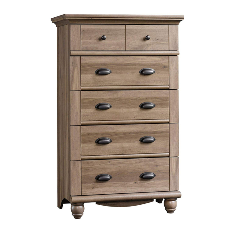
4-Drawer Chest
Model 420850
NOTE: THIS INSTRUCTION
BOOKLET CONTAINS IMPORTANT
SAFETY INFORMATION.
PLEASE READ AND KEEP FOR
FUTURE REFERENCE.
English pg 1-18
Français pg 19-21
Español pg 22-24
Lot # 530890 06/25/19
Purchased: __________________
sauder.com
CONTACT US FIRST
BEFORE MAKING ANY RETURNS TO THE STORE.
Share your journey!
sauder.com
CONTACT US FIRST
BEFORE MAKING ANY RETURNS TO THE STORE.
Visit sauder.com/service to order replacement parts, view video assembly tips, or chat with a live rep.
Prefer the phone? Give us a ring at 1-800-523-3987.
Customer Service is available Monday-Friday - 9 a.m. to 5:30 p.m. EST (except holidays)
WARNING
CHOKING HAZARD - Small Parts
Not for children under 3 years.
Adult assembly required.
No. 2 Phillips Screwdriver
Tip Shown Actual Size
Table of Contents Assembly Tools Required
Hammer
Not actual size
Skip the power trip.
This time.
2-3
4
5-18
19-21
22-24
25-26
27
Part Identification
Hardware Identification
Assembly Steps
Français
Español
Safety
Warranty
420850 www.sauder.com/servicePage 2
A2 RIGHT END (1)
B2 LEFT END (1)
C2 TOP (1)
D BACK (1)
D36 RIGHT DRAWER SIDE (4)
D37
LEFT DRAWER SIDE (4) - 1 with label
D175 DRAWER BACK (4)
D982 DRAWER BOTTOM (4)
E BACK BRACE (1)
F FRONT BRACE (1)
G BRACE (1)
H DRAWER FRONT (4)
I BASE (1)
J TOP MOLDING (1)
M67
DRAWER BRACE (4)
(Hidden part using recycled
material. Color may vary.)
åWhile not all parts are labeled, some of the parts will have a label or an inked letter on the edge
to help distinguish similar parts from each other. Use this part identification to help identify similar parts.
Now you know
our ABCs.
Part Identification
Part Identification
420850www.sauder.com/service Page 3
A2
B2
C2
D
E
F
G
H
I
J
D36
D37
D175
D982
M67
åScrews are shown actual size. You may receive extra hardware with your unit.
420850 www.sauder.com/servicePage 4
BLACK 1-1/8" PAN HEAD SCREW - 4
9S
BLACK 9/16" LARGE HEAD SCREW - 24
1S
SILVER 1-1/8" FLAT HEAD SCREW - 3
10S
BLACK 1-1/4" FLAT HEAD SCREW - 2
7S
3S GOLD 5/16" FLAT HEAD SCREW - 32
METAL PIN - 2
1R
TACK
GLIDE - 6
13E
NAIL - 38
1N
HIDDEN
CAM - 14
1F CAM DOWEL - 14
2F
35AA UNIVERSAL
CABINET RAIL - 8 35AC DRAWER RIGHT - 435AD DRAWER LEFT - 4
DRAWER FRONT
BRACKET - 4
9G
METAL
BRACKET - 4
4G
30S BLACK 1-9/16" FLAT HEAD SCREW - 20
KNOB - 4
137K FURNITURE TIPPING RESTRAINT KIT - 1
97
Hardware Identification
å Assemble your unit on a carpeted floor or on the empty carton
to avoid scratching your unit or the floor.
å Push fourteen HIDDEN CAMS (1F) into the ENDS (A2 and B2)
and BRACES (E, F, and M67). Then, insert the metal end of a
CAM DOWEL (2F) into each HIDDEN CAM.
420850www.sauder.com/service Page 5
(14 used)
Arrow
1F
2F
Insert the metal end of the CAM
DOWEL into the HIDDEN CAM.
Arrow
Do not tighten the HIDDEN CAMS in this step.
A2
B2
E
F
M67
M67
M67
M67
Step 1 Look for this icon. It means a
video assembly tip is available at
www.sauder.com/service/tips
Step 2
420850 www.sauder.com/servicePage 6
GOLD 5/16" FLAT HEAD SCREW
(16 used in this step)
3S
A2
B2
1
2
3
Surface with
HIDDEN CAMS
Surface with
HIDDEN CAMS
Finished edge
2
3
1
Finished edge
å Fasten the UNIVERSAL CABINET RAILS* (35AA) to the
ENDS (A2 and B2 ). Use sixteen GOLD 5/16" FLAT HEAD
SCREWS (3S) through holes #1 and #3.
å *patent pending glide system
Glide end
Glide end
1
2
3
1
2
3
1
2
3
2
3
1
2
3
1
2
3
1
VIEW THE DRAWER GLIDE VIDEO
Step 3
420850www.sauder.com/service Page 7
Remember:
Righty tighty.
Lefty loosey.
å Fasten four METAL BRACKETS (4G) to the BASE (I). Use
four BLACK 9/16" LARGE HEAD SCREWS (1S).
BLACK 9/16" LARGE HEAD SCREW
(4 used in this step)
1S
4G
4G
I
Step 4
420850 www.sauder.com/servicePage 8
å Fasten the LEFT END (B2) to the TOP (C2). Tighten two
HIDDEN CAMS.
å Fasten the BACK BRACE (E) to the LEFT END (B2).
Tighten two HIDDEN CAMS.
Start Tighten
Arrow
Minimum
190 degrees
Caution
Risk of damage or
injury. HIDDEN CAMS
must be completely
tightened. HIDDEN
CAMS that are not
completely tightened
may loosen, and parts
may separate. To
completely tighten:
Arrow
Maximum
210 degrees
B2
Finished edge
E
C2
Surface with HIDDEN CAMS
Surface
with
HIDDEN
CAMS
Rounded edge
Surface with holes
These edges must be even.
Do not stand the unit upright without the
BACK fastened. The unit may collapse.
Caution
Step 5
420850www.sauder.com/service Page 9
Arrow
Minimum
190 degrees
Maximum
210 degrees
B2
E
C2
F
A2
1R
å Insert two METAL PINS (1R) into the FRONT BRACE (F).
å Fasten the FRONT BRACE (F) to the LEFT END (B2).
Tighten the HIDDEN CAM.
å NOTE: Be sure the METAL PIN in the FRONT BRACE
inserts into the hole in the LEFT END.
å Fasten the RIGHT END (A2) to the TOP (C2) and
BRACES (E and F). Tighten five HIDDEN CAMS.
å NOTE: Be sure the METAL PIN in the FRONT BRACE
inserts into the hole in the RIGHT END.
Surface without
HIDDEN CAMS
Finished edge
Surface with HIDDEN CAMS
Finished edge
Step 6
420850 www.sauder.com/servicePage 10
å Fasten the TOP MOLDING (J) to the TOP (C2). Use three
SILVER 1-1/8" FLAT HEAD SCREWS (10S).
å NOTE: Do not overtighten the SCREWS into the TOP.
å Fasten the BASE (I) to the ENDS (A2 and B2). Use four
BLACK 9/16" LARGE HEAD SCREWS (1S) through the
METAL BRACKETS on the BASE and into the ENDS.
B2
C2
A2
J
I
SILVER 1-1/8" FLAT HEAD SCREW
(3 used for the TOP MOLDING)
10S
Curved edge
BLACK 9/16" LARGE HEAD SCREW
(4 used for the BASE)
1S
Curved edge
Step 7
420850www.sauder.com/service Page 11
å Fasten the BRACE (G) to the BACK BRACE (E). Use two
BLACK 1-1/4" FLAT HEAD SCREWS (7S). Now might be a
good time to refresh
your drink.
E
G
BLACK 1-1/4" FLAT HEAD SCREW
(2 used in this step)
7S
Step 8
420850 www.sauder.com/servicePage 12
å Carefully turn your unit over onto its front edges. Unfold
the BACK (D) and lay it over your unit.
å Make equal margins along all four edges of the BACK (D).
Push on opposite corners of your unit if needed to make
it "square".
å Fasten the BACK (D) to your unit using the NAILS (1N).
å Using your hammer, gently tap six TACK GLIDES (13E)
into the ENDS (A2 and B2) and BASE (I).
NAIL
(38 used in this step)
1N
D
B2
A2
I
13E
13E
Do not stand the unit upright without the
BACK fastened. The unit may collapse.
Caution
This hole must be here.
These two TACK GLIDES
should be flush with the
front surface of the BASE.
13E
Step 9
420850www.sauder.com/service Page 13
å Pull the DRAWER FRONT BRACKETS (9G) apart and slide them into the
grooves in the DRAWER SIDES (D36 and D37). You may need to gently tap
them in with a hammer.
å NOTE: The DRAWER FRONT BRACKETS are marked “RH” and “LH” for
easy identification.
å Fasten the DRAWER FRONT (H) to the DRAWER FRONT BRACKETS (9G).
Use four BLACK 9/16" LARGE HEAD SCREWS (1S).
å Repeat this step for the other drawers.
VIEW THE T-SLOT BOX VIDEO
Push down
BLACK 9/16" LARGE HEAD SCREW
(16 used in this step)
1S
D36
D37
H
9G
9G
Step 10
420850 www.sauder.com/servicePage 14
å Slide the DRAWER BOTTOM (D982) into the grooves in the
DRAWER SIDES (D36 and D37) and DRAWER FRONT (H).
å Fasten the DRAWER BRACE (M67) to the DRAWER FRONT (H).
Tighten one HIDDEN CAM.
å Repeat this step for the other drawers.
Arrow
Minimum
190 degrees
Maximum
210 degrees
Be sure the DRAWER
BOTTOM inserts into the
DRAWER FRONT groove.
With the palm of
your hand, tap
the DRAWER
BOTTOM down
into the groove.
D36
M67
D982
D37
H
H
Surface with HIDDEN CAM
VIEW THE T-SLOT BOX VIDEO
Unfinished surface
Hidden part using
recycled material.
Color may vary.
Step 11
420850www.sauder.com/service Page 15
å Fasten the DRAWER BACK (D175) to the DRAWER SIDES (D36
and D37) and DRAWER BRACE (M67). Use five BLACK 1-9/16"
FLAT HEAD SCREWS (30S).
å Repeat this step for the other drawers.
D175
Be sure the DRAWER
BOTTOM inserts into the
DRAWER BACK groove.
30S
Start each screw a few turns before
completely tightening any of them.
BLACK 1-9/16" FLAT HEAD SCREW
(20 used in this step)
M67
D36
D37
VIEW THE T-SLOT BOX VIDEO
Step 12
420850 www.sauder.com/servicePage 16
å Fasten a DRAWER RIGHT (35AC) to the RIGHT DRAWER SIDE (D36) and a DRAWER LEFT (35AD) to the LEFT DRAWER
SIDE (D37). Use four GOLD 5/16" FLAT HEAD SCREWS (3S) through holes #1 and #2.
å NOTE: The glides are not intended to rotate.
å Now, fasten the KNOB (137K) to the DRAWER FRONT (H). Use a BLACK 1-1/8" PAN HEAD SCREW (9S).
å Repeat this step for the other drawers.
1
2
1
2
D36
D37
H
BLACK 1-1/8" PAN HEAD SCREW
(4 used for the KNOBS)
9S
Glide end
Glide end
GOLD 5/16" FLAT HEAD SCREW
(16 used in this step)
3S
(4 screws per drawer)
137K
VIEW THE DRAWER GLIDE VIDEO
Step 13
420850www.sauder.com/service Page 17
å Carefully stand your unit upright in its final location. We recommend using the SAFETY STRAP for added stability.
å Open the FURNITURE TIPPING RESTRAINT KIT (97).
å NOTE: Do not turn the SAFETY DRYWALL ANCHOR into a wall stud. If you prefer to fasten the SAFETY
STRAP to a wall stud, go to your local hardware store for proper hardware.
å INSTALLATION INSTRUCTIONS:
1. Insert the SAFETY DRYWALL ANCHOR through the WASHER and one end of the SAFETY STRAP.
2. Using a Phillips screwdriver or a hand drill, press the screw slightly onto the drywall.
3. Apply pressure; turn the screw until a pilot hole is made and the nylon sheath slips through.
4. Turn the screw until it is flush against the wall and you feel a firm resistance.
5. Continue to turn until the screw starts spinning freely.
å Carefully cut out the perforated hole in the BACK (D). Insert the other end of the SAFETY STRAP through this hole, then
use the BLACK 9/16" LARGE HEAD SCREW through the SAFETY STRAP and into the pre-drilled hole in the underside of
the TOP (C2).
å NOTE: Before moving your unit to a dierent location, unscrew the SAFETY DRYWALL ANCHOR from your wall. The
nylon sheath will remain behind your wall.
D
BLACK 9/16" LARGE HEAD SCREW
(1 used in this step)
97
Safety
drywall
anchor
Safety strap
Washer
C2
WARNING AVERTISSEMENT ADVERTENCIA
occurfromfurnituretip-over. To help
preventtip-over:
•Installtip-overrestraintprov ided.
•Placeheaviestitemsin thelower
drawers.
•Do not set TV’s or other heavy objects on
topof this product, unless the product is
drawers,d oors, orshelves.
•Neveropenmorethanone drawer
atatime.
Useoftip-overrestraintsmayonly
reduce,butnot eliminate, therisk
oftip-over.
This is a permanent label. Donot remove!
écrasementpeuventsurvenir si le mobilier
bascule.Pourprévenir le basculement :
•Installerledispositif anti-basculement fourni.
•Placerlesarticlespluslourdsdansles
tiroirsinférieurs.
•Nepasmettredetéléviseuroud’autre objets
lourdssurle dessusdecemeuble, s auf si le
•Nejamaisouvrir plusd’untiroir à la fois.
L’utilisationdedispositifsanti-basculement
peutréduirele risquedebasculement, m ais
pasl’éliminer.
Cette étiquette est permanente. Nepas
l’enlever!
puedenocurrirporel volcardelosmuebles.
Paraayudar a prevenir quesevolqué:
•Instalarlacontenciónbrindadaparaevitar
quesevolqué.
•Coloquelosartículosmáspesadosenlos
cajonesinferiores.
•Nocoloquetelevisoresuotrosobjetos
pesadosenlaparte superiordeeste producto,
diseñadoparaacomodarlos.
•Nuncapermitaquelosniñossesubano se
•Nuncaabramásdeuncajóna la vez.
Elusodela contenciónpuedesolamente
Esta esunaetiqueta permanente. ¡Noremover!
Step 14
30 lbs.
50 lbs.
30 lbs. each
420850 www.sauder.com/servicePage 18
å To insert the drawers into your unit, tip the front of the drawers down and drop the glides on the drawers behind the glides
on the unit. Lift the front of the drawers up and slide them into the unit.
å NOTE: Be sure the label on the LEFT DRAWER SIDE is in the UPPER drawer.
å To make adjustments to the drawers, loosen the SCREWS in the DRAWER FRONT BRACKETS, make needed
adjustments, and tighten the SCREWS.
å NOTE: Please read the back pages of the instruction booklet for important safety information.
å This completes assembly. Clean with a damp cloth. Wipe dry.
To make adjustments
to the drawers, loosen
the SCREWS in the
DRAWER FRONT
BRACKETS and the
SCREWS in holes
#3, make needed
adjustments, and
tighten the SCREWS.
WARNING
Children have died from
furniture tipover. To reduce
the risk of furniture tipover:
• ALWAYS install tipover
restraint provided.
• NEVER put a TV on this
product.
• NEVER allow children to
stand, climb, or hang on
drawers, doors, or shelves.
• NEVER open more than one
drawer at a time.
• Place heaviest items in the
lowest drawers.
This is a permanent label.
Do not remove!
1/19 526119
And to celebrate, why not share your success story at Walmart.com or
A l’usage exclusif du
Canada Noter la date
d’achat de cet élément
et conserver le livret
pour future référence.
Pour contacter Sauder
en ce qui concerne cet
élément, faire référence
au numéro de lot et
numéro de modèle en
appelant notre numéro
sans frais.
Lot nº : ____________
Date de
l’achat: ____________
LISTE DE PIÈCES
REFERENCE DESCRIPTION QUANTITÉ
LISTE DE PIÈCES
REFERENCE DESCRIPTION QUANTITÉ
NOUS SOMMES LA POUR VOUS AIDER!
Nous faisons de notre mieux pour nous assurer que votre meuble
arrive dans d’excellentes conditions. Nos représentants du service
Clientèle sont aimables et prêts à vous aider au cas où une pièce
aurait été endommagée ou manquerait (ou si vous aviez besoin
d’aide pour l’assemblage). NE RAMENEZ PAS LE MEUBLE AU
MAGASIN. Au Canada, composez ce numéro d’appel gratuit:
1-800-523-3987
Du lundi au vendredi, de 9 heures du matin à
5:30 heures du soir (horaire Côte Est)
(sauf jours fériés)
Si une pièce a besoin d’être remplacée, la pièce de remplacement
sera envoyée dans les 48 heures. (Sauf week-ends et jours fériés)
Utilisez les instructions d’assemblage en français avec les
schémas étape par étape du manuel d’instruction en anglais.
Chaque étape en français correspond à la même étape
en anglais. La pièce devant être attachée à l’élément est
représentée en gris sur les schémas de chaque étape pour plus
de précision. Comparer la “Liste de pièces” ci-dessous avec
la “PART IDENTIFICATION” du manuel en anglais pour vous
familiariser avec les pièces avant l’assemblage.
REMARQUE : CE MANUEL D’INSTRUCTIONS CONTIENT
D’IMPORTANTES INFORMATIONS RELATIVES À LA SÉCURITÉ.
À LIRE ET CONSERVER POUR TOUTE RÉFÉRENCE FUTURE.
Commode 4 TiroirsModèle 420850
35AA
GLISSIÈRE D'ÉLÉMENT UNIVERSELLE.....8
35AC
TIROIR DROIT................................................................4
35AD
TIROIR GAUCHE..........................................................4
13E PATIN.....................................................................................6
1F EXCENTRIQUE ESCAMOTABLE...................14
2F CHEVILLE D'EXCENTRIQUE ............................14
4G CONSOLE EN MÉTAL.............................................4
9G CONSOLE DE DEVANT DE TIROIR..............4
137K BOUTON............................................................................4
1N CLOU ................................................................................38
1R GOUPILLE EN MÉTAL.............................................2
1S VIS TÊTE LARGE 14 mm NOIRE..................24
3S VIS TÊTE PLATE 8 mm DORÉE ..................32
7S VIS TÊTE PLATE 32 mm NOIRE.....................2
9S VIS TÊTE GOUTTE DE
SUIF 28 mm NOIRE..................................................4
10S VIS TÊTE PLATE 28 mm ARGENTÉE.........3
30S VIS TÊTE PLATE 40 mm NOIRE ................20
97 KIT DE RETENUE ANTI-BASCULEMENT
POUR MOBILIER...........................................................1
A2 EXTRÉMITÉ DROITE..................................................1
B2 EXTRÉMITÉ GAUCHE...............................................1
C2 DESSUS...............................................................................1
D ARRIÈRE ..............................................................................1
D36 CÔTÉ DROIT DE TIROIR.......................................4
D37 CÔTÉ GAUCHE DE TIROIR.................................4
1 avec étiquette
D175 ARRIÈRE DE TIROIR..................................................4
D982
FOND DE TIROIR.........................................................4
E ENTRETOISE ARRIÈRE............................................1
F ENTRETOISE FRONTALE......................................1
G ENTRETOISE....................................................................1
H DEVANT DE TIROIR...................................................4
I SOCLE..................................................................................1
J MOULURE DE DESSUS..........................................1
M67 ENTRETOISE DE TIROIR
(Pièce cachée utilisant des matériaux
recyclés. La couleur peut varier.)......................4
420850www.sauder.com/service Page 19
ÉTAPE 1
Ne pas serrer les EXCENTRIQUES ESCAMOTABLES dans
cette étape.
Assembler l'élément sur un sol à moquette ou sur le carton vide
pour éviter d'endommager l'élément ou le sol.
Enfoncer quatorze EXCENTRIQUES ESCAMOTABLES (1F) dans les
EXTRÉMITÉS (A2 et B2) et les ENTRETOISES (E, F et M67). Ensuite,
insérer l'extrémité en métal de la CHEVILLE D'EXCENTRIQUE (2F)
dans chaque EXCENTRIQUE ESCAMOTABLE.
ÉTAPE 2
Fixer les GLISSIÈRES D'ÉLÉMENT UNIVERSELLES* (35AA) aux
EXTRÉMITÉS (A2 et B2). Utiliser seize VIS TÊTE PLATE 8 mm
DORÉES (3S) à travers les trous nº 1 et nº 3.
*système de coulisse en instance de brevet
ÉTAPE 6
Fixer la MOULURE DE DESSUS (J) au DESSUS (C2). Utiliser trois
VIS TÊTE PLATE 28 mm ARGENTÉES (10S).
Fixer le SOCLE (I) aux EXTRÉMITÉS (A2 et B2). Utiliser quatre VIS
TÊTE LARGE 14 mm NOIRES (1S) à travers les CONSOLES EN
MÉTAL sur le SOCLE et dans les EXTRÉMITÉS.
REMARQUE : Ne pas trop serrer les VIS dans le DESSUS.
ÉTAPE 7
Fixer l'ENTRETOISE (G) à l’ENTRETOISE ARRIÈRE (E). Utiliser
deux VIS TÊTE PLATE 32 mm NOIRES (7S).
ÉTAPE 3
Fixer quatre CONSOLES EN MÉTAL (4G) au SOCLE (I). Utiliser
quatre VIS TÊTE LARGE 14 mm NOIRES (1S).
ÉTAPE 8
Attention: Ne pas relever l'élément dans sa position verticale
avant d'avoir fixé l’ARRIÈRE. L'élément risque de s'eondrer.
Avec précaution, retourner l'élément sur ses chants avant. Déplier
l'ARRIÈRE (D) et le placer sur l'élément.
Veiller à avoir des marges égales le long des quatre chants de
l'ARRIÈRE (D). Si besoin est, enfoncer sur les coins opposés de
l'élément pour s'assurer d'être « d'équerre ».
Fixer l'ARRIÈRE (D) à l'élément à l'aide des CLOUS (1N).
À l'aide d'un marteau, enfoncer légèrement six PATINS (13E) dans
les EXTRÉMITÉS (A2 et B2) et le SOCLE (I).
ÉTAPE 4
Attention: Ne pas relever l'élément dans sa position verticale
avant d'avoir fixé l’ARRIÈRE. L'élément risque de s'eondrer.
Fixer l'EXTRÉMITÉ GAUCHE (B2) au DESSUS (C2). Serrer deux
EXCENTRIQUES ESCAMOTABLES.
Fixer l'ENTRETOISE ARRIÈRE (E) à l'EXTRÉMITÉ GAUCHE (B2).
Serrer deux EXCENTRIQUES ESCAMOTABLES.
Attention: Risque des dégâts ou blessures. Les Excentriques
Escamotables doivent être serrés à bloc. Les Excentriques
Escamotables que ne sont pas serrées à bloc peuvent desserrer
et les pièces peuvent séparer. Pour serrer à bloc, faire tourner
l'excentrique escamotable de 210 degrés.
ÉTAPE 9
Séparer les CONSOLES DE DEVANT DE TIROIR (9G) et les
enfiler dans les rainures des CÔTÉS DE TIROIR (D36 et D37). Il
est peut-être nécessaire de les enfoncer délicatement à l'aide d'un
marteau.
REMARQUE : Les CONSOLES DE DEVANT DE TIROIR ont
l'inscription "RH" (Droite) et l'inscription "LH" (Gauche) pour
faciliter leur identification.
Fixer un DEVANT DE TIROIR (H) aux CONSOLES DE DEVANT DE
TIROIR (9G). Utiliser quatre VIS TÊTE LARGE 14 mm NOIRES (1S).
Répéter cette étape pour les autres tiroirs.
ÉTAPE 5
Insérer deux GOUPILLES EN MÉTAL (1R) dans
l'ENTRETOISE AVANT (F).
Fixer l’ENTRETOISE AVANT (F) à l'EXTRÉMITÉ
GAUCHE (B2). Serrer un EXCENTRIQUE ESCAMOTABLE.
REMARQUE : S'assurer de bien insérer la GOUPILLE EN MÉTAL située
sur l’ENTRETOISE AVANT dans le trou dans l'EXTRÉMITÉ GAUCHE.
Fixer l'EXTRÉMITÉ DROITE (A2) au DESSUS (C2) et aux
ENTRETOISES (E et F). Serrer cinq EXCENTRIQUES ESCAMOTABLES.
REMARQUE : S'assurer de bien insérer la GOUPILLE EN MÉTAL située
sur l’ENTRETOISE AVANT dans le trou dans l'EXTRÉMITÉ DROITE.
ÉTAPE 10
Enfiler le FOND DE TIROIR (D982) dans les rainures des CÔTÉS
DE TIROIR (D36 et D37) et du DEVANT DE TIROIR (H).
Fixer l'ENTRETOISE DE TIROIR (M67) au DEVANT DE TIROIR (H).
Serrer un EXCENTRIQUE ESCAMOTABLE.
Répéter cette étape pour les autres tiroirs.
420850 www.sauder.com/servicePage 20

Other Sauder Indoor Furnishing manuals

Sauder Lateral File 107302 User manual

Sauder

Sauder Lateral File 107302 User manual

Sauder Worksense BERGEN CIRCLE 426459 User manual

Sauder

Sauder Worksense BERGEN CIRCLE 426459 User manual

Sauder Harbor View 403794 User manual

Sauder

Sauder Harbor View 403794 User manual

Sauder 420612 User manual

Sauder

Sauder 420612 User manual

Sauder 411614 User manual

Sauder

Sauder 411614 User manual

Sauder Manhattan Gate 429254 User manual

Sauder

Sauder Manhattan Gate 429254 User manual

Sauder OfficeWorks AFFIRM 427444 User manual

Sauder

Sauder OfficeWorks AFFIRM 427444 User manual

Sauder 420456 User manual

Sauder

Sauder 420456 User manual

Sauder 414356 User manual

Sauder

Sauder 414356 User manual

Sauder Harbor View 158002 User manual

Sauder

Sauder Harbor View 158002 User manual

Sauder 414817 User manual

Sauder

Sauder 414817 User manual

Sauder International Lux 417828 User manual

Sauder

Sauder International Lux 417828 User manual

Sauder Palladia Hutch 412308 User manual

Sauder

Sauder Palladia Hutch 412308 User manual

Sauder North Avenue 425190 User manual

Sauder

Sauder North Avenue 425190 User manual

Sauder Cannery Bridge 415910 User manual

Sauder

Sauder Cannery Bridge 415910 User manual

Sauder Harvey Park 420288 User manual

Sauder

Sauder Harvey Park 420288 User manual

Sauder 420566 User manual

Sauder

Sauder 420566 User manual

Sauder HomePlus Series User manual

Sauder

Sauder HomePlus Series User manual

Sauder Cottage Road 420136 User manual

Sauder

Sauder Cottage Road 420136 User manual

Sauder Storage Cabinet 419496 User manual

Sauder

Sauder Storage Cabinet 419496 User manual

Sauder 411606 User manual

Sauder

Sauder 411606 User manual

Sauder Shoal Creek 408920 User manual

Sauder

Sauder Shoal Creek 408920 User manual

Sauder 414289 User manual

Sauder

Sauder 414289 User manual

Sauder 408726 User manual

Sauder

Sauder 408726 User manual

Popular Indoor Furnishing manuals by other brands

Regency LWMS3015 Assembly instructions

Regency

Regency LWMS3015 Assembly instructions

Furniture of America CM7751C Assembly instructions

Furniture of America

Furniture of America CM7751C Assembly instructions

Safavieh Furniture Estella CNS5731 manual

Safavieh Furniture

Safavieh Furniture Estella CNS5731 manual

PLACES OF STYLE Ovalfuss Assembly instruction

PLACES OF STYLE

PLACES OF STYLE Ovalfuss Assembly instruction

Trasman 1138 Bo1 Assembly manual

Trasman

Trasman 1138 Bo1 Assembly manual

Costway JV10856 manual

Costway

Costway JV10856 manual
moss DESIGN Caisson Credenza Assembly instructions

moss DESIGN

moss DESIGN Caisson Credenza Assembly instructions

Aquaglide FULL DECK 15.0 owner's manual

Aquaglide

Aquaglide FULL DECK 15.0 owner's manual

AREBOS AR-HE-SW30 user manual

AREBOS

AREBOS AR-HE-SW30 user manual

Till-Hilft Fulda 87005.330 Assembly instructions

Till-Hilft

Till-Hilft Fulda 87005.330 Assembly instructions

Twoey Outside 2010 quick start guide

Twoey Outside

Twoey Outside 2010 quick start guide

Hettich Easys 200 operating instructions

Hettich

Hettich Easys 200 operating instructions

The bedboss RELAX 404 Series owner's manual

The bedboss

The bedboss RELAX 404 Series owner's manual

Oeseder Möbelindustrie Bern 991 720 Assembly instructions

Oeseder Möbelindustrie

Oeseder Möbelindustrie Bern 991 720 Assembly instructions

Costway HW68469 user manual

Costway

Costway HW68469 user manual

Next ALIX A27743 Assembly instructions

Next

Next ALIX A27743 Assembly instructions

BROSA Hans Assembly guide

BROSA

BROSA Hans Assembly guide

Prodigg MINIKA PBA015T-FUR installation manual

Prodigg

Prodigg MINIKA PBA015T-FUR installation manual

manuals.online logo
manuals.online logoBrands
  • About & Mission
  • Contact us
  • Privacy Policy
  • Terms and Conditions

Copyright 2025 Manuals.Online. All Rights Reserved.