Savaria ES-125 User manual

OWNER’S MANUAL
(To Be Retained by Owner After Installation
by Authorized Savaria Dealer)
Part No. 000703
04-m07-2011
ES-125
Inclined Platform Lift

2
ES-125 Owner’s Manual Part No. 000703, 04-m07-2011
IMPORTANT
Ensure that only an authorized Savaria Dealer installs and services the Savaria™
ES-125 Inclined Platform Lift. Under no circumstances is anyone other than a
dealer with Savaria training and authorization to install, adjust, service or
modify any mechanical or electrical device on this equipment. Failure to follow
this warning can result in safety system compromises or defeat; this can result
in serious injury or death. Savaria accepts no liability for property damage,
warranty claims or personal injury, including death, in this circumstance.
Passenger safety is the result of countless details in the equipment’s design,
manufacture, and installation. After installation, reliable operation and
continual safe operation requires regular service and inspection at least twice
per year, or more frequently where usage, environment, or local jurisdiction
requires. As the Owner, you are responsible for ensuring that regular service
and inspections occur in a timely manner.
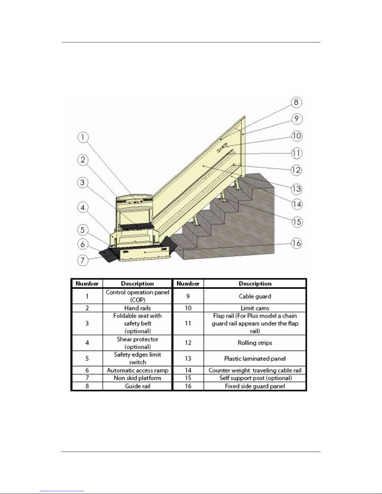
Refer to this manual for specifications, operating instructions and maintenance
of the Savaria™ ES-125 Inclined Platform Lift.
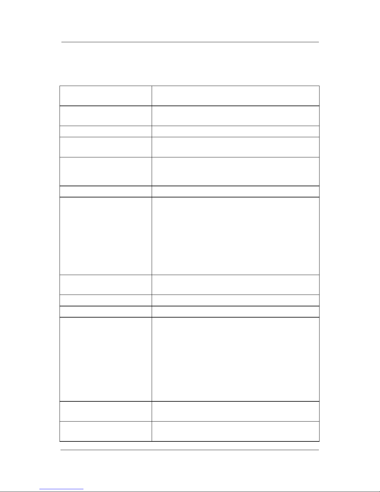
Upon completion of installation, the dealer must provide you with the
following information and ensure it is recorded in this manual. In addition,
either the dealer or you must keep any service and/or maintenance records in
the Maintenance Record section of this manual.
WARRANTY
Ensure your Savaria Dealer provides you with a copy of the manufacturer’s
limited parts warranty and documentation relating to any Dealer labour
warranty.
-------------------------------------------------------------------------------------------------
FOR OWNER’S RECORDS
Customer Name: _________________________________________
Installing Dealer: _________________________________________
Dealer’s Telephone Number: _______________________________
Date Installed: ___________________________________________
Serial/Job Number: _______________________________________

3
Part No. 000703, 04-m07-2011 ES-125 Owner’s Manual
Table of Contents
TO ENSURE SAFE OPERATION . . . . . . . . . . . . . . . . . . . . . . . . . . . . . . . . . . . . . . . . . . . . . .4
1. DESCRIPTION . . . . . . . . . . . . . . . . . . . . . . . . . . . . . . . . . . . . . . . . . . . . . . . . . . . . . . . . . . .5
2. GENERAL SPECIFICATIONS . . . . . . . . . . . . . . . . . . . . . . . . . . . . . . . . . . . . . . . . . . . . . .6
3. OPERATION . . . . . . . . . . . . . . . . . . . . . . . . . . . . . . . . . . . . . . . . . . . . . . . . . . . . . . . . . . . . .8
Operating from the COP Controls . . . . . . . . . . . . . . . . . . . . . . . . . . . . . . . . .8
Operating from the Landing Station Controls . . . . . . . . . . . . . . . . . . . . .9
4. SAFETY FEATURES . . . . . . . . . . . . . . . . . . . . . . . . . . . . . . . . . . . . . . . . . . . . . . . . . . . . .10
Underpan Sensors (Optional) . . . . . . . . . . . . . . . . . . . . . . . . . . . . . . . . . . . .10
Flap Sensitive Switches (Optional) . . . . . . . . . . . . . . . . . . . . . . . . . . . . . . .10
Arm Position Switches (Optional) . . . . . . . . . . . . . . . . . . . . . . . . . . . . . . . .10
Seat Position Switch (Optional) . . . . . . . . . . . . . . . . . . . . . . . . . . . . . . . . . .10
Platform Position Switch (Optional) . . . . . . . . . . . . . . . . . . . . . . . . . . . . . .10
Emergency Stop Buttons (Optional) . . . . . . . . . . . . . . . . . . . . . . . . . . . . . .10
Manual Lowering Device . . . . . . . . . . . . . . . . . . . . . . . . . . . . . . . . . . . . . . . .11
5. MAINTENANCE . . . . . . . . . . . . . . . . . . . . . . . . . . . . . . . . . . . . . . . . . . . . . . . . . . . . . . . .12
Maintenance Schedule . . . . . . . . . . . . . . . . . . . . . . . . . . . . . . . . . . . . . . . . . .12
Maintenance Record . . . . . . . . . . . . . . . . . . . . . . . . . . . . . . . . . . . . . . . . . . . .13
Operator Troubleshooting . . . . . . . . . . . . . . . . . . . . . . . . . . . . . . . . . . . . . . .14

4
ES-125 Owner’s Manual Part No. 000703, 04-m07-2011
TO ENSURE SAFE OPERATION
To ensure safe operation of this equipment, pay careful attention to the
important notes below.
• Read this manual carefully before using the ES-125 Inclined Platform
Lift.
• To prevent accidents, adhere strictly to the instructions and keep clear
of moving parts at all times.
• Follow instructions on all equipment labels at all times. Replace any
damaged labels immediately.
• Ensure that only qualified personnel perform maintenance.

5
Part No. 000703, 04-m07-2011 ES-125 Owner’s Manual
1. DESCRIPTION
Figure 1 shows the exterior components of the ES-125.
Figure 1

6
ES-125 Owner’s Manual Part No. 000703, 04-m07-2011
2. GENERAL SPECIFICATIONS
ES-125 Specifications
Applications Indoor residential or public
Outdoor package is optional
Configurations Standard model: under the stairway machine room
Plus model: top of the stairway drive cabinet
Load capacity 450 lb (204 kg)
Maximum travel Standard model: 23 ft (7000 mm)
Plus model: 15 ft (4572 mm)
Travel speed
Standard model (residential): 16 ft/min (0.08 m/s)
Standard model (public): 18 ft/min (0.09 m/s)
Plus model: 21 ft/min (0.11 m/s)
Rail Heavy gauge steel composite
Platform sizes
(with non-skid surface)
27.5” x 36” (700 mm x 914 mm)
28.5” x 44” (724 mm x 1118 mm)
30” x 48” (762 mm x 1219 mm)
30” x 44” (762 mm x 1118 mm)
Platform can be folded manually or there is an
optional power-fold platform.
Unit folds up to within 11” (279 mm) of the wall
(residential).
Access ramps Two positive-action access ramps for incline or 90
degree entry
Power supply 110 VAC, 15A, 60 Hz, single phase
Motor assembly 110 VAC, 1/2 hp (373 W), 1750 rpm / gear reducer 50:1
Drive unit
Standard model: Steel aircraft cable 3/16” (5 mm)
with breaking load of 4200 lb (1950 kg). The deviator
pulley, controller and winding drum are in a machine
room.
Plus model: Roller chain #50 and steel aircraft cable
with breaking load of 6100 lb (2767 kg). The electric
motor gear reducer and controller are self-enclosed
at the top landing in a drive cabinet. No machine
room is required.
Controller ETL certified to CSA and ASME standards
24 VAC or 12 VDC operating controls
Platform operating controls Continuous-pressure directional buttons with a key
switch for increased safety

7
Part No. 000703, 04-m07-2011 ES-125 Owner’s Manual
Call stations Continuous-pressure directional buttons at each
landing
Finish Electrostatic powder coat paint on steel surfaces and
ABS vacuum -formed plastics
Safety features
Automatic dual access ramps
Underpan sensors
Obstruction sensors on access ramps
Mechanical emergency brake
Slack cable switch
Non-skid surface on platform and ramps
Keyed continuous-pressure directional buttons
Upper and lower limit switches
Two handles on car
Options
Three-position manual safety arms
Two-position motorized safety arms
Power-fold platform
Flush cabinet at front or back of rail (Plus model)
Manual lowering device
Motor with electromechanical brake
Manually-raised side flap
Automatically-raised side flap
Safety edge on ramp
Fold-up seat with seat belt
Post for call/send station
Self-support posts
Outdoor package
12-volt battery operation
Audio visual alarm
Zero clearance at top landing to avoid landing door
(n/a on Plus model)
Fire service function
Hand-held pendant control on platform
Pre-drilled guide rail for masonry walls
Formica colors available on back sides of rail
Custom color

8
ES-125 Owner’s Manual Part No. 000703, 04-m07-2011
3. OPERATION
Operating from the COP Controls
Figure 2 shows the ES-125 car operating panel (COP). Note that the controls on
your unit may differ from those shown here.
Figure 2
To operate the ES-125 from the COP controls:
1Insert the key into the key switch and turn it to the ON position to activate
the operating buttons.
2Apply constant pressure on the UP/DOWN switch (as required) to move the
platform to the desired landing.
3When the lift reaches the landing, release the UP/DOWN switch.
4To prevent unauthorized use of the lift, take the key out when the unit is not
in operation.
5Pressing the Emergency Stop button (optional) during travel will stop the
lift immediately. The Emergency Stop overrides the landing station controls.
Pull the Emergency Stop out to return the lift to normal operation.

9
Part No. 000703, 04-m07-2011 ES-125 Owner’s Manual
Operating from the Landing Station Controls
Figure 3 shows the landing station (hall call) controls. Note that your landing
station controls may differ from those shown here.
Figure 3
To operate the ES-125 from the landing (call/send) station controls:
1Insert the key into the key switch and turn it to the ON position to activate
the operating buttons.
2Apply constant pressure on the appropriate button to call the platform to
the desired landing.
3When the lift reaches the landing, release the switch.
4To prevent unauthorized use of the lift, take the key out when the unit is not
in operation.
5Pressing the Emergency Stop button (optional) during travel will stop the
lift immediately. The Emergency Stop overrides the landing station controls.
Pull the Emergency Stop out to return the lift to normal operation.

10
ES-125 Owner’s Manual Part No. 000703, 04-m07-2011
4. SAFETY FEATURES
Underpan Sensors (Optional)
The underpan sensors (if equipped) are located under the platform. These
sensors detect any obstacles and stop the platform if something obstructs it.
Flap Sensitive Switches (Optional)
The flap sensitive switches (if equipped) are located under the platform. These
switches detect any obstacles and stop the platform if something obstructs it.
Arm Position Switches (Optional)
The arm position switches (if equipped) are located at the inside ends of the
arms. These switches stop the platform if the arms are in an intermediate
position (any position other than horizontal or vertical).
Seat Position Switch (Optional)
The seat position switch (if equipped) is located under the seat. This switch
ensures that the power-fold platform does not fold up when the seat is down.
Platform Position Switch (Optional)
The platform position switches are located on the lower part of the frame.
These switches prevent the platform from moving unless it is entirely folded or
unfolded.
Emergency Stop Buttons (Optional)
Pressing a red Emergency Stop button during travel will stop the lift
immediately and activate the alarm. The Emergency Stop overrides the landing
(call/send) stations. Pull the Emergency Stop out to return the lift to normal
operation.

11
Part No. 000703, 04-m07-2011 ES-125 Owner’s Manual
Manual Lowering Device
In case of an emergency, you can lower the platform manually using the
manual lowering device.
NOTE
The manual lowering mechanism is for emergency use only.
ES-125 (unit pulled by a steel cable, residential model)
The residential ES-125 does not come
standard with the manual lowering device; the
crank must be ordered separately if you want
this feature. The device functions the same as
for the public unit described below.
Figure 4
ES-125 P (unit pulled by a steel cable, public
model)
In an emergency, you can move the ES-125 P
manually with a crank. See Figure 4. Insert the
crank and turn it to move the unit toward the
desired position at the landing. Always be sure
to remove the crank when you’re done.
ES-125 Plus (chain-driven unit)
Figure 5
In an emergency, you can move the ES-125 Plus
manually with the plastic wheel located at the
top of the motor in the cabinet. See Figure 5.
Release the brake lever by lifting it and then turn
the wheel to move the unit toward the desired
position at the landing.

12
ES-125 Owner’s Manual Part No. 000703, 04-m07-2011
5. MAINTENANCE
The owner can perform the 2-month inspections, but the 6-month
inspections must be performed by a Qualified Technician. Contact your
Authorized Dealer.
Maintenance Schedule
Verification by owner Frequency
Verify general operation of the lift. Every 2 months
Verify correct operation of the safety devices:
• Underpan sensor switches (optional)
• Flap sensitive switches (optional)
• Emergency stop buttons (optional)
• Platform position switch (folded/unfolded)
• Arm position switches (optional)
• Seat position switch (optional)
Every 2 months
Clean bus lines (if equipped) with grit #400 sandpaper. Every 2 months
Verification by technician ONLY Frequency
Verify the entire suspension system:
• Chain or steel cable
• Steel cable on brake assembly
• Connecting links or cable clips
• Fastening of motor and deflecting pulleys (optional)
Every 6 months
Perform a safety brake test. Every 6 months
Verify the following:
• Rail anchors (to wall)
• Slack cable switch (test)
• Final limit switches
• Rollers (lubricate if noisy)
• Up and down relays (make sure the relays are not stuck in
the activated position by reading continuity through a
normally open (N.O.) contact)
Every 6 months
NOTE

13
Part No. 000703, 04-m07-2011 ES-125 Owner’s Manual
Maintenance Record
Date Time Reason for Call Comments Dealer

14
ES-125 Owner’s Manual Part No. 000703, 04-m07-2011
Operator Troubleshooting
The following table lists potential problems and their possible solutions.
If the problem persists, contact your Authorized Dealer.
Potential Problem Possible Solution
Platform travels up but not
down
Check the underpan sensor. Pull down on the
underpan to ensure the pan is not stuck in the
activated position.
Check the flap on the lower part of the lift. Move
it to ensure the switch (if equipped) is not stuck
in the activated position.
Platform travels down but not
up
Check the flap on the upper part of the lift. Move
it to ensure the switch (if equipped) is not stuck
in the activated position.
Platform does not move in
either direction
Check the power supply (breaker, cord, etc.).
Check that the key is ON (if applicable).
Check to see if the Emergency Stop is pushed in;
it should be pulled out for normal operation.
If the platform is at the top landing, check the
underpan sensor and the flap on the lower part
of the lift as described above.
If the platform is at the bottom landing, check
the flap on the upper part of the lift as explained
above.
Check that the arms are not in an intermediate
position. They should be in a horizontal or
vertical position.
Platform does not fold or unfold
(power-fold option only)
Check that the lift is stopped at one of the
landings.
Check that the seat is folded up.
Platform moves intermittently
Check to see if the bus lines (if equipped) are
dirty. If necessary, clean with grit #400
sandpaper.


ES-125 Inclined Platform Lift
OWNER’S MANUAL
Part No. 000703
Copyright © 2011
Savaria Corporation
Elevators and Lifts
www.savaria.com
Sales
107 Alfred Kuehne Blvd.
Brampton, Ontario, L6T 4K3, Canada
Tel: (905) 791-5555
Fax: (905) 791-2222
Toll Free: 1-800-661-5112
Other manuals for ES-125
1
Table of contents
Other Savaria Stairlift manuals