SEA FULL TANK 100 User manual

FULL TANK
SEA S.r.l.
Zona Ind. S.Atto 64020 TERAMO Italy
Tel. +39.0861.588341 - Fax+39.0861.588344
e-mail: [email protected]
WEB SITE : www.seateam.com
EnglishEnglish
INSTALLATION MANUAL
and Securit y I nformation
HY DRAU LIC OPERATOR FOR SWING GATE
Cod. 67410845 REV 02 - 06/2009
Sistemi Elettronici
di Apertura Porte e Cancelli
International registered trademark n. 804888
®
16
FULL TANK 100 FULL TANK 200
1 A
40 bar 30 bar
130°C
230 V (±5%) 50/60 Hz
220 W
270 mm 390 mm
70
-20°C +55°C
640da N
12,5uF
12,8 Kg 15,2 Kg
Ip55
6 mt 7 mt
90° / 125°
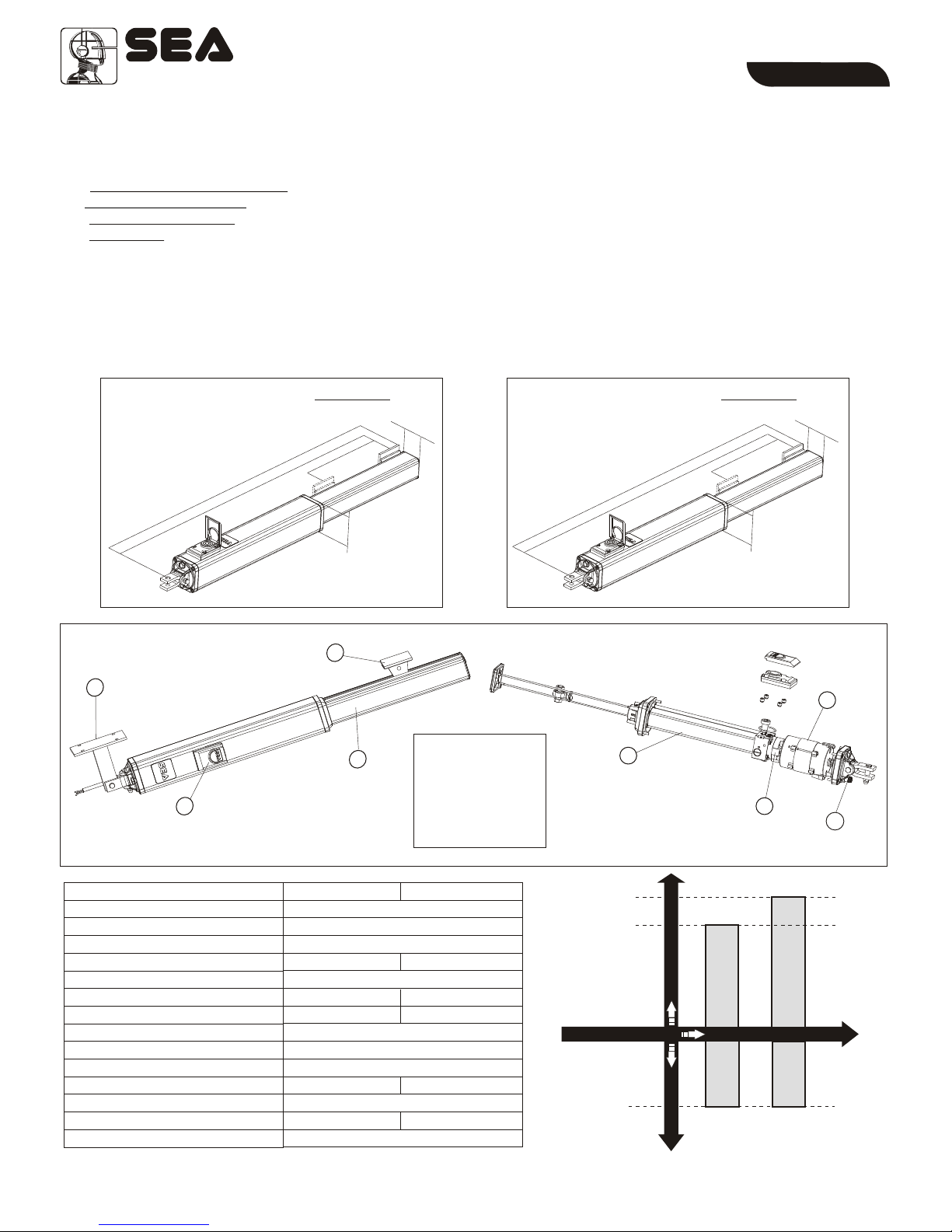
FEATURES AND SPECIFICATIONS
The FULL TANK is a high quality hydraulic operator for condominium use for gates with leaf lengths up to max. 7 m.
SA (with lock only in opening)
The lock is guaranteed for leaf lengths up to 180 m with the 100 version and up to 2,20 m with the 200 version. For leaf lengths
exceeding 2,20 m it is necessery, in all versions, to install an electric lock.
Available in the following versions:
AC (with lock in opening and closing)
SC (with lock only in closing)
SB (without lock)
The Full Tank is supplied with by-pass valves for the power regulation in both opening and closing. Electronic adjustable slow down
in opening and closing with control board GATE 2. For the European laws and directives actually in force it is strongly recommended
to use the Safety Gate (device for the reading of the gate position), for reverse in case of obstacle.
USING GRAPHIC
FULL TANK OPERATOR
FULL TANK 100
7 mt
70
FULL
TANK 100
1. Shaft cover
2. Release
3. Front bracket
4. Rear bracket
5. Cylinder
6. Electric motor
7. Hydraulic pump
8. Exit electric cables
FULL TAN K
Dimensions (mm)
EnglishEnglish
Dimensions (mm)
FULL
TANK 200 FULL TANK 200
6 mt
TECHNICAL FEATURES
Operating temperatures
Thermal protection
M
P
Power supply
Power
Absorbed current
Stroke
Cycles hour (at a temp. of 20°C)
Max working pressure
ax Thrust
Capacitor
Weight
rotection class
Max leaf lenght
Opening degree of the leaf
CICLES/HOUR
OPERATORS
Max. leaf length
17
Cod. 67410845
Sistemi Elettronici
di Apertura Porte e Cancelli
International registered trademark n. 804888
®
REV 02 - 06/2009
11
33
44
22
Fig. 3
Fig. 1
FULL TANK 100 FULL TANK 200
Fig. 2
5
6
7
8
01 52
09 8
02 7
90
56
1270
211 5
390
90
65

FU LL TANK
Release
By-pass valves
EnglishEnglish
Clevis Attachment
Rear attachment
Breather screw
Pin rear
attachment
(short)
Brass Pin (long)
Front bracket
Shaft Cover
End cover
Cod. 67410845
Sistemi Elettronici
di Apertura Porte e Cancelli
International registered trademark n. 804888
®
REV 02 - 06/2009
18
Fig. 4
11
33
44
1010
1010
11
77
1212
1212
55
99
88
22
66
22
11
52x1,
2x1
3x1 SCH.
3 1 Hx SC .
3x1,5
2x1
RG 58
3x1,5
3x1,5
2x1
13 x
FULL TAN K
EnglishEnglish
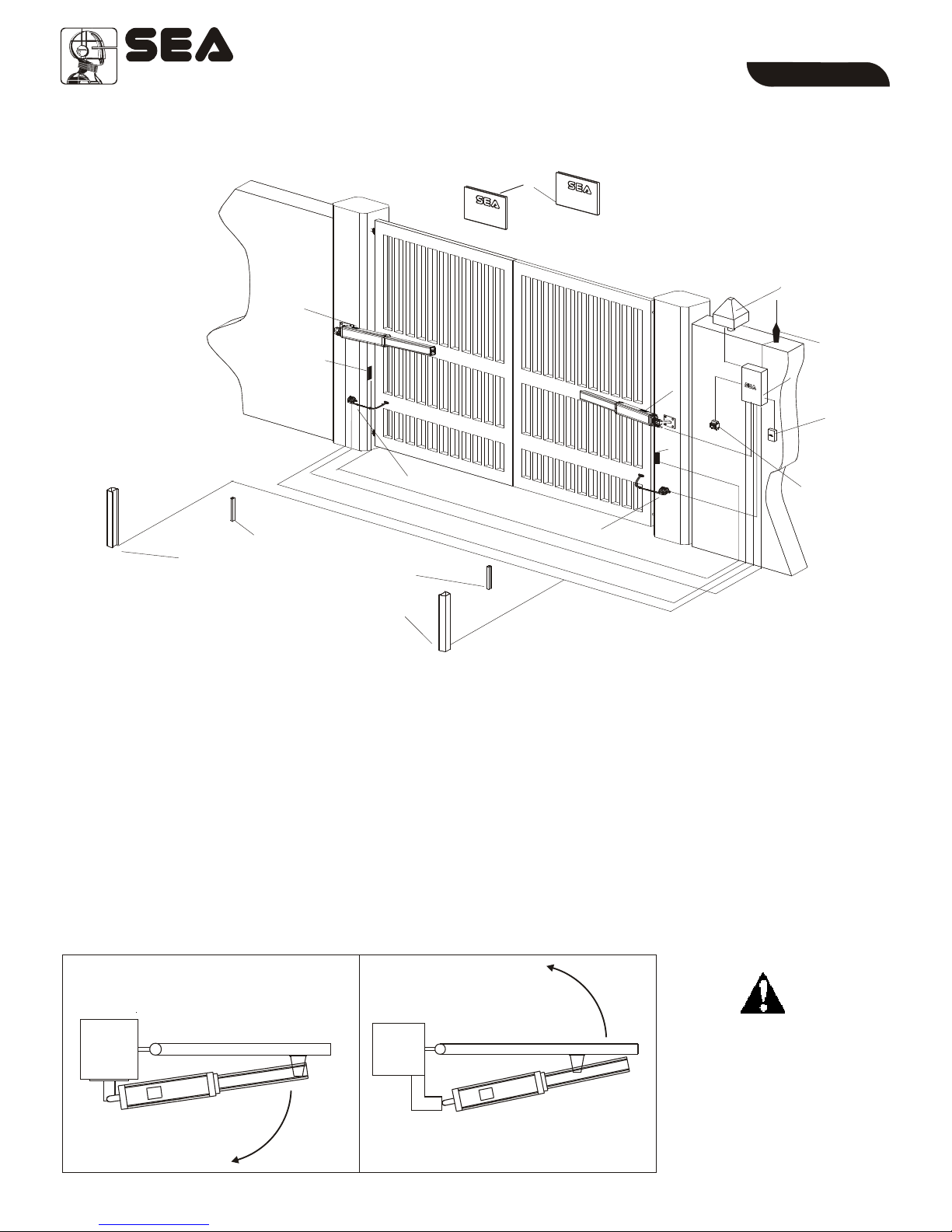
TYPICAL INSTALLATION
INSIDE
OUTSIDE
1. Full Tank operator
2. Mechanical stop
3. Gate 2 control board
4. Warning lamp
5. Photocell tx
6. Differential switch 16A-0,03A
7. Photocell rx
8. Key switch start-stop
9. Antenna
10. Column for photocells
11. Warning notice
12. Safety Gate
TYPE OF INSTALLATION
It is possible to install the Full Tank with opening inside (Fig.5) or opening outside (Fig.6).
Install the operator always
inside the property
inside inside
Outside
Outside
Inward installation Outward installation
Cod. 67410845
Sistemi Elettronici
di Apertura Porte e Cancelli
International registered trademark n. 804888
®
REV 02 - 06/2009
Fig. 5 Fig. 6
19
a
d
b
c
Fig. 7
a
d
b
c
Fig. 7 encore
FULL TAN K
EnglishEnglish
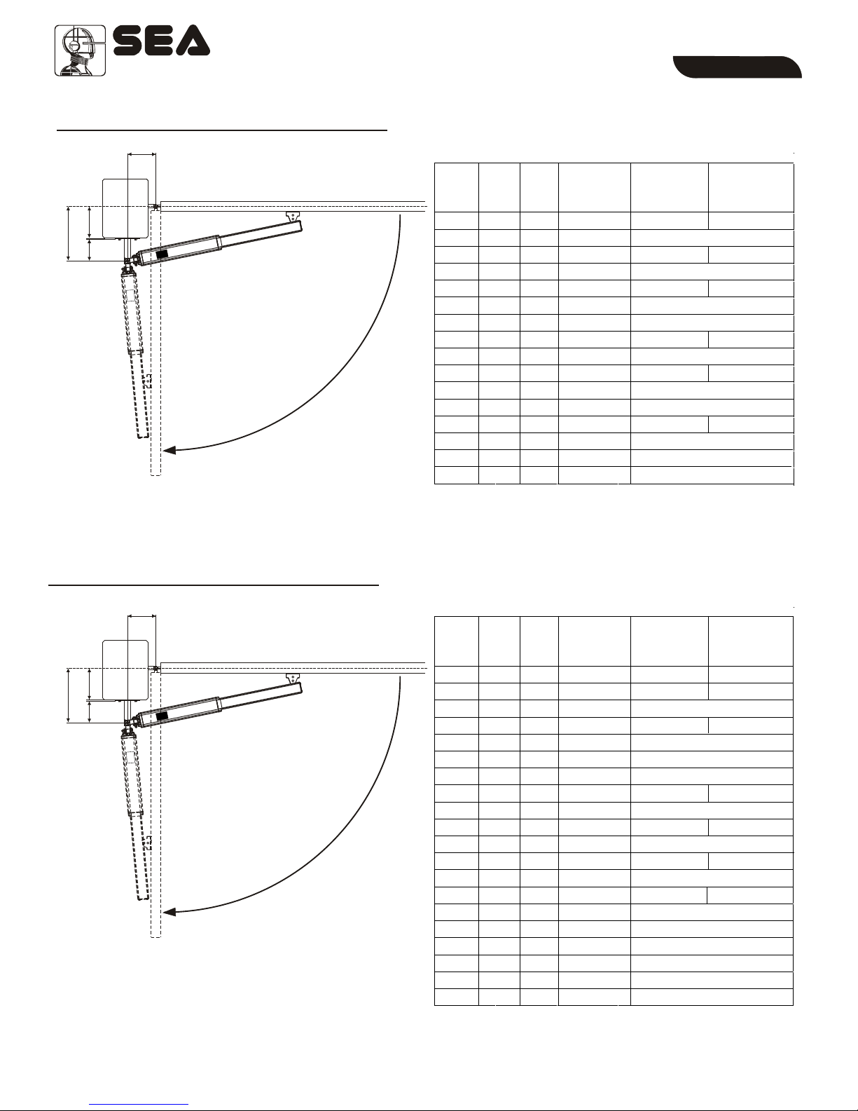
INSIDE OPENING INSTALLATION
To obtain 110° with d > 55 mm it is necessary to make a niche in the gate.
INSIDE OPENING INSTALLATION
To obtain 125° with d > 55 mm it is necessary to make a niche in the gate.
Outside
Outside
Inside
Inside
Total stroke 270 mm - max. recommended stroke 250 mm
a b d
max Max.
Opening
Angle
(mm) (mm) (mm)
250 215
250
250
215
250 225
250 235
255 242
250 242
250
250
100
100
105
105
120
120
125
140
140
145
145
150
155
160
170
180
115
150
110
145
105
130
125
95
110
95
105
100
85
90
75
65
50
50
55
55
70
70
75
90
90
95
95
100
105
110
120
130
110°
90°
110°
90°
106°
90°
90°
100°
90°
100°
90°
90°
96°
90°
92°
92°
250
250
250
250
250
253
245
Max. Stroke
(mm)
Stroke
for 90°(mm)
Total stroke 390 mm - max. recommended stroke 370 mm
a b d
max Max.
Opening
Angle
(mm) (mm) (mm)
368 295
372 300
372
370
370
310
370 330
370
371
355
355
370
370
360
365
369
370
370
125
130
140
145
145
160
175
185
185
195
195
240
240
250
250
260
260
270
280
295
170
170
235
165
230
210
195
145
190
140
175
110
125
105
115
95
100
90
80
65
75
80
90
95
95
110
120
130
130
140
140
185
185
195
195
205
205
215
230
245
125°
125°
90°
120°
90°
90°
90°
110°
90°
110°
90°
100°
90°
95°
90°
95°
90°
90°
90°
90°
370
370
370
370
370
370
369
Stroke
max (mm)
Stroke
for 90°(mm)
Cod. 67410845
Sistemi Elettronici
di Apertura Porte e Cancelli
International registered trademark n. 804888
®
REV 02 - 06/2009
20

a
d
b
c
Fig. 8
a
d
b
c
Fig. 8 encore
FULL TAN K
EnglishEnglish
OUTSIDE OPENING INSTALLATION
OUTSIDE OPENING INSTALLATION
Inside
Outside
Inside
Outside
a b Max.
Opening
Angle
(mm) (mm)
250 240
250
250
243
241
150
160
165
175
180
180
90
90
80
80
70
65
95°
90°
95°
90°
90°
90°
250
249
Stroke
max (mm)
Stroke
for 90°(mm)
Total stroke 270 mm - max. recommended stroke 250 mm
a b Max.
Opening
angle
(mm) (mm)
356 342
345 336
330
335
319
250
255
265
270
275
275
100
95
95
90
90
90
100°
95°
95°
90°
90°
90°
325
342
Max. Stroke
(mm)
Stroke for
90°(mm)
Stroke 390 mm - max. recommended stroke 370 mm
Cod. 67410845
Sistemi Elettronici
di Apertura Porte e Cancelli
International registered trademark n. 804888
®
REV 02 - 06/2009 21
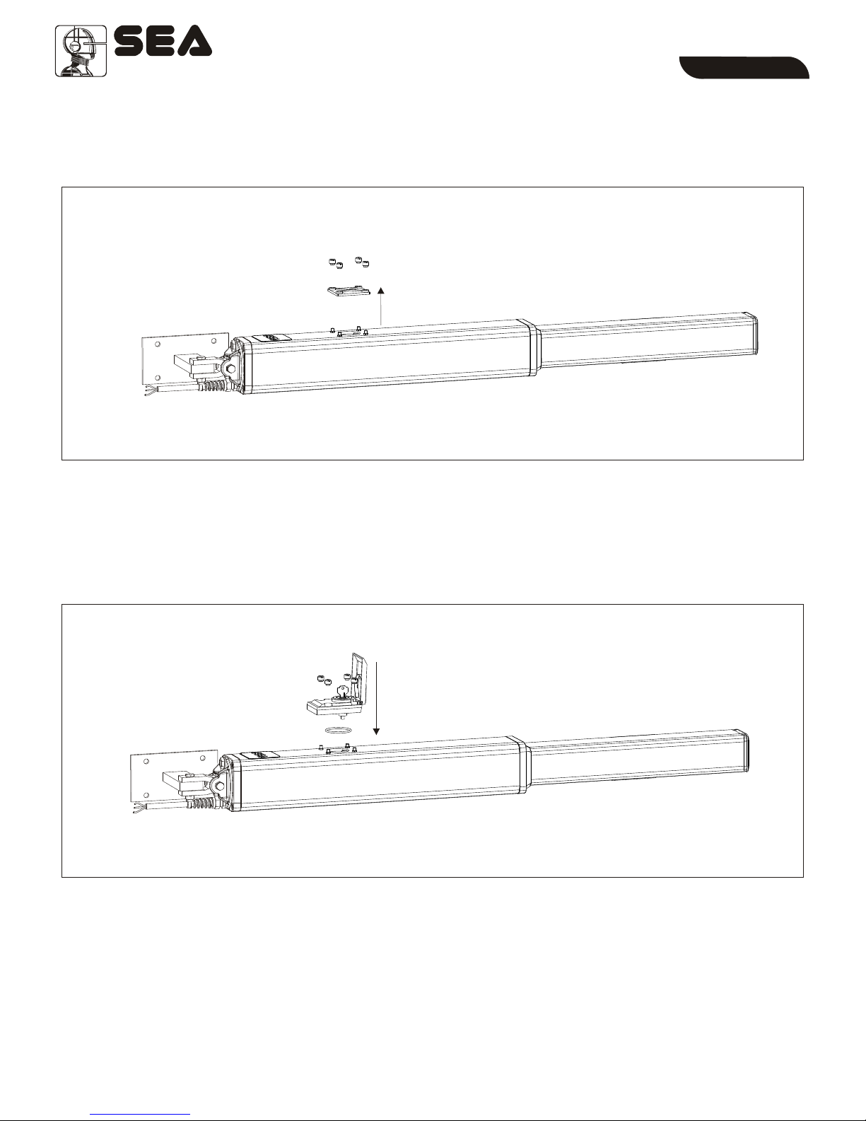
RELEASE MOUNTING
Remove the transporting plate as shown in Fig. 9.
Mount the release as shown in Fig. 10.
FULL TAN K
EnglishEnglish
Cod. 67410845
Sistemi Elettronici
di Apertura Porte e Cancelli
International registered trademark n. 804888
®
REV 02 - 06/2009
Fig. 9
Fig. 10
22

Fig. 13
Fig. 14
98 mm
8 m5 m
55 mm
65 mm
FULL TAN K
EnglishEnglish
ØOpen carefully the package, making sure
not to loose parts which are listed in fig. 4
ØAttach the rear oscillating bracket as shown
in fig. 12
Attention: Do not use a hammer for the
insertion of the short brass pin; its fitting into
the bracket and clevis attachment must be
done by the simple pressure of the hands.
Attention: Do not incline the hydraulic
operator further than the allowed angle of the
oscillating bracket (1), risks the possible
braking of it.
INSTALLATION OF THE OSCILLATING REAR BRACKET
Adjustable rear bracket (with screws)
(Accessory on demand)
INSTALLATION OF REAR BRACKET
According to the type of opening that you have chosen
(inside or outside) and to the chosen leaf rotation (see
pag. 20-21), the rear bracket must first be cut respecting
the quote “a” on pag. 20-21 and then welded as in fig. 13.
The support must be positioned so that the operator is
perfectly levelled (Fig. 13, Fig. 15)
Cod. 67410845
Sistemi Elettronici
di Apertura Porte e Cancelli
International registered trademark n. 804888
®
REV 02 - 06/2009
Fig. 11
Fig. 12
(1)
23

Fig. 17 Fig. 18
70 mm 70 mm
6m
3,5 m
46 mm
POSITIONING OF THE FRONT BRACKET
Once the operator is attached to the post and the leaf set in the closed position execute the following
operations:
1. Release the operator (as in fig. 24 pag.12)
2. Pull-out completely the chromate shaft and push it back in 1cm
3. Attach the shaft to the front bracket (Fig. 16)
4. Set the operator perfectly levelled and mark the position of the front bracket (Fig.15)
Attention: avoid the welding of the front bracket to the shaft of the hydraulic operator already attached;
the welding scraps (daps) could ruin the chromium plating of the shaft.
Front bracket welded
Front bracket screwed
WELDING OF THE FRONT BRACKET TO THE GATE
The front bracket must be positioned so that the operator is perfectly levelled
According to the nature of the gate the front bracket (wood, steal, Aluminium) can be:
FULL TAN K
EnglishEnglish
Cod. 67410845
Sistemi Elettronici
di Apertura Porte e Cancelli
International registered trademark n. 804888
®
REV 02 - 06/2009
Fig. 16
Fig. 15
24
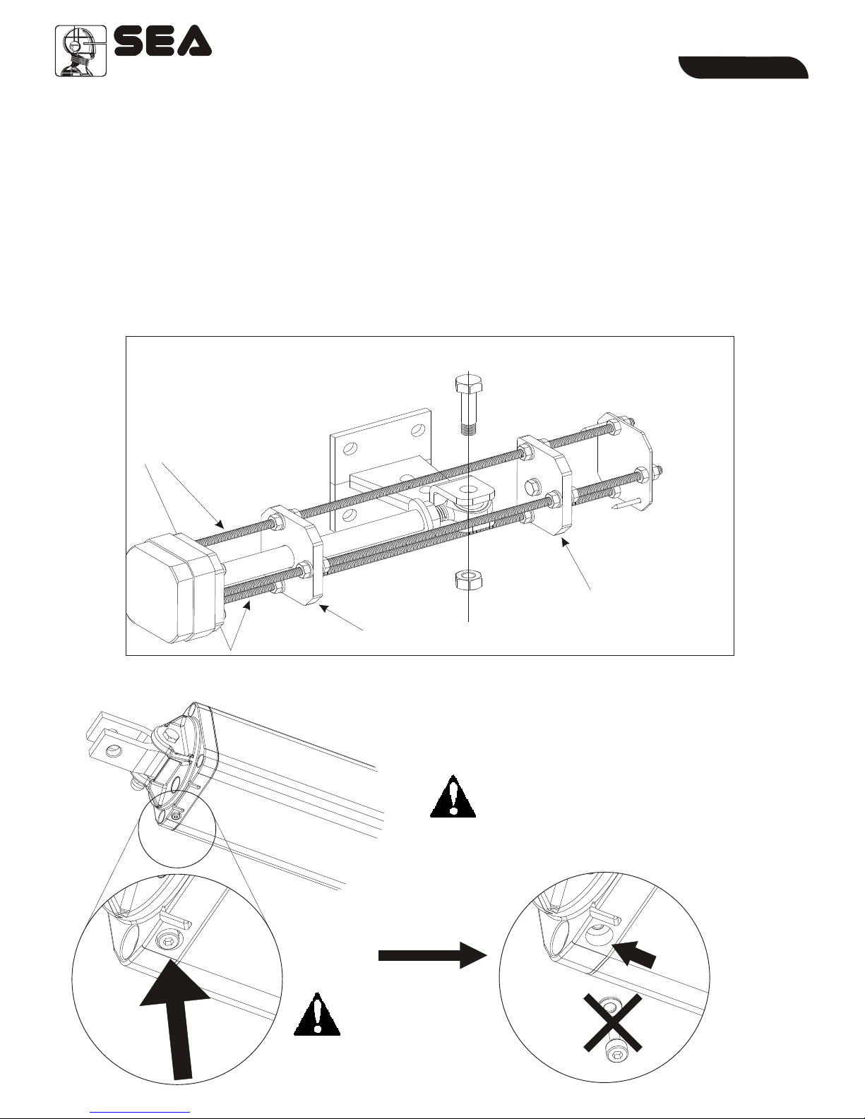
Fig. 19
Disc 1
Disc 2
INSTALLATION OF POSITIVE STOPS
ØRelease the unit (as in fig. 24 of page 27)
ØMake the shaft come out for ¾ of its stroke
ØPut the positive stops into the front flange of the unit with the two tie rods (of the three present on the stops)
which are parallel to the gate (Fig.19)
ØFix the positive stops with the provided screws
Ø
ØAt this point couple the shaft to the front bracket
ØTo adjust the positive stops in opening act on disk 1 and in closing act on disk 2.
Attention: The mounting of the mechanical positive stops does not cause the reduction of the shaft
stroke.
Insert the ball joint after having installed the stops.
rods parallel to the gate
BREATHER SCREW
Up
down
Unscrew and
remove at the
end of installation
ATTENTION
It is obligatory to remove the breather
screw at the end of the installation.
FULL TAN K
EnglishEnglish
Sistemi Elettronici
di Apertura Porte e Cancelli
International registered trademark n. 804888
®
Fig. 20
Fig. 21
OK
Cod. 67410845 REV 02 - 06/2009 25

+-
+-
Fig. 22
TORQUE ADJUSTMENT (by pass valves)
By-Pass Valves
s
u
s
e
r
r
e
p
i
n
g
n
o
i
t
p
a
e
r
n
e
i
n
p
g
O
u
s
s
e
r
r
e
p
i
g
n
n
i
c
t
l
o
a
r
s
e
i
n
p
g
O
Grey
Yellow
Grey Yellow
Adjust the opening and closing forces of the gate so that the diagram of the force is respected (present in the
regulation EN 12453); Anyway the max. thrust force should never be superior of 15 KgF.
INSTALLATION OF THE CHROME PLATED SHAFT COVER
FULL TAN K
EnglishEnglish
Cod. 67410845
Sistemi Elettronici
di Apertura Porte e Cancelli
International registered trademark n. 804888
®
REV 02 - 06/2009
Fig. 23
26
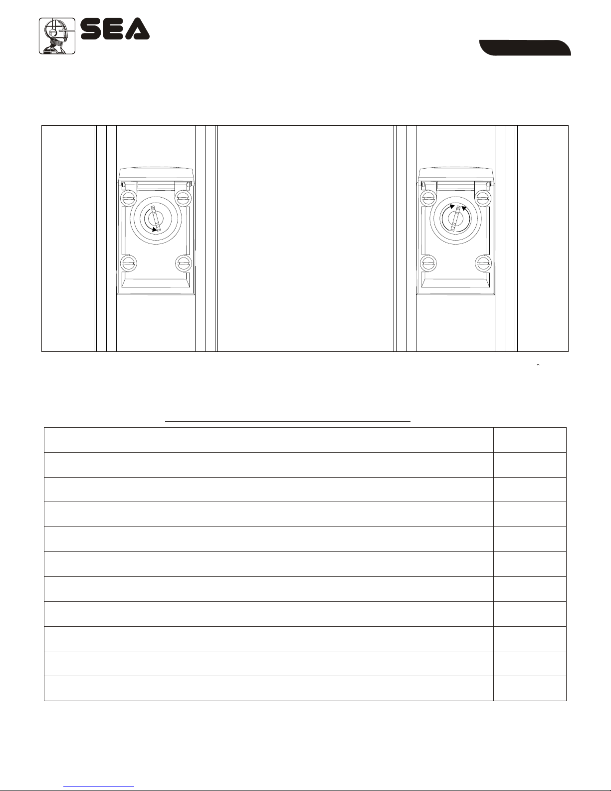
Fig. 25
To release, open the lid, insert the
key, rotate starting from the stop of
departure from ½ turn to a
maximum of 1 turn (360°) in anti-
clockwise direction (see fig.24).
Attention: Turning the key over 1
turn (360°) could damage the
release .
To re-lock, turn the key into
clockwise direction to the
maximum, afterwards bring back
the key into the position 0, turn it
again in anti-clockwise direction
(see fig. 25), remove the key and
close the little door again.
Fig. 24
0
WARNING: SEA recommends to the end user to release the operator only after having switched off the electric power.
Always contact a professional installer in case of not correct working of the operator.
MANUAL RELEASE SYSTEM
WARNING: Always switch off the main power (110V or 230V) before servicing the operator.
All the above described operations MUST be made exclusively by an authorized installer.
1) Check the solidity and the stability of the gate, especially the points of support and/or rotation of
the gate (pivots).
2) Check the oil level of the hydraulic/in oil bath operators (cap on rear cover of the Full Tank)
3) Change the hydraulic oil with the one recommended from the head company
4) Check the release function
5) Check the by-pass valves function
6) Check and lubricate the fixing pins
7) Check the integrity of the connection cables
8) Check the function and the positive stops condition in opening and closing (where there is
present a mechanical positive stop accessory)
9) Check the good status of all parts which are forced (rear bracket, oscillating bracket and front
bracket).
10) Check the operating of all accessories, especially the function of all safety devices and of the
Safety Gate.
11) After having executed the periodical maintenance operations it is necessary to repeat the
test and the putting in service of the automation
PERIODI CAL MAI NTENANCE
Annual
Annual
4 years
Annual
Annual
Annual
Annual
Annual
Annual
Annual
Annual
FULL TAN K
EnglishEnglish
Cod. 67410845
Sistemi Elettronici
di Apertura Porte e Cancelli
International registered trademark n. 804888
®
REV 02 - 06/2009 27

Fig.26
RISK EXAMINATION
The points pointed by arrows are potentially dangerous. The installer must take a thorough risk examination
to prevent crushing, conveying, cutting, grappling, trapping so as to guarantee a safe installation for people, things
and animals.
(
)
As for misunderstandings that may arise refer to your
area distributor or call our help desk. These instructions
are part of the device and must be kept in a well known
place.The installer shall follow the provided intructions
thoroughly. products must only be used to automise
doors, gates and lwings. Any initiative taken without
explicit authorization will preserve the manufacturer
from whatsoever responsibility. The installer shall
provide warning notices on not assessable further risks.
in its relentless aim to improve the products, is
allowed to make whatsoever adjustment without giving
notice. This doesn’t oblige to up-grade the past
production. can not be deemed responsible for any damage or accident caused by product breaking, being
damages or accidents due to a failure to comply with the instructions herein. The guarantee will be void and the
manufacturer responsibility will be nullified if original spare parts are not being used.
Packaging materials such as plastic bags, foam polystyrene, nails etc must be kept out of children’s reach as dangers
may arise.
in fig. 26
Re. Laws in force in the country where installation has
been made.
SEA
SEA
SEA
SEA
SEA
SEA The electrical installation
shall be carried out by a professional technician who will release documentation as requested by the laws in force.
INITIAL TESTAND STARTING OF THE AUTOMATION
After having completed the necessary operations for a correct installation of the Full Tank product, as
described in this manual, and after having valuated all resting risks which could arise in any installation, it is
necessary to test the automation to guaranty the maximum security and, in particular way, to guaranty
that the laws and norms of this sector are fully respected. Especially the test must be executed following
the norm EN 12445 which establishes the methods of tests for checking the gate automations respecting the
limits established by the rule EN 12453.
SAFETY GATE
For a correct and safe installation it is
strongly recommended to install a
Safety Gate, which allows the
fulfilment of the force diagram
included in the norm EN 12453 and
consequently the test and start of the
whole installation.
FULL TAN K
EnglishEnglish
Cod. 67410845
Sistemi Elettronici
di Apertura Porte e Cancelli
International registered trademark n. 804888
®
REV 02 - 06/2009
28

SELF INSTALL - NEED TECHNICAL
ASSISTANCE?
OPTION 1: DIRECT WITH THE SERVICE DESK – QUICKEST AND MOST EFFECTIVE METHOD
Submit your enquiry direct with the service desk at – service@automaticsolutions.com.au
The service desk has the most experienced staff in Australia to help with your problem but they need your help.
Describe your problem in detail and as clearly as possible. Don’t forget to include a telephone number.
Be certain to detail which model or models of you are working with.
Send photos of the installation – they love photos. The people at the service desk are good but they are
even better when they can see the installation. Send photos of the overall scene so they can see the
entire installation. Also send photos of the wiring to the control board and any other part of the
installation you think is relevant.
Send video if appropriate. Smartphone’s these days take remarkably good video in small file sizes which
can be emailed in a moment. If your problem needs a video to show the issue please feel free to send it.
NOTE: THIS IS BY FAR THE FASTEST AND MOST SUCCESFUL WAY TO SOLVE YOUR PROBLEM
PHOTOS AND VIDEOS ARE THE NEXT BEST THING TO BEING THERE
OPTION 2: LODGE YOUR ENQUIRY LOCALLY - SLOWER BUT CAN STILL BE EFFECTIVE
Make contact with the store of purchase. Branch staffs are typically not technicians and dependent on their length
of service will have varying degrees of technical knowledge. If they cannot help however they will certainly either
source help locally from their technicians or make contact with the service technicians on your behalf.
OPTION 3: SERVICE CALL WITH AUTOMATIC SOLUTIONS TECHNICIAN – SLOWEST METHOD
If you fall within the local branch service area it may be possible to book a local technician to look at your
installation. Wait times will vary dependent on local workloads. The cost is a service fee which includes the first
half hour and the hourly rate thereafter. If any Automatic Solutions provided parts are found to be defective and
within warranty these will be provided free of charge.
(NOTE: If you suspect that any parts are defective and within warranty you may wish to consider option 4)
A note on this option: If you decide on this option you will be asked to sign an “authorisation to proceed” which
will provide legal authority and payment security. This form has three options available of which only the first two
are available to you. The third option is for warranty repairs only for full install customers. Self install customers
requiring warranty only service need to refer to option four below.
IMPORTANT: IN SHORT THIS OPTION WILL INCUR CHARGES
OPTION 4: RETURN THE PRODUCT IF BELIEVED TO BE FAULTY
As a self install customer who has purchased product if you believe the product to be faulty rather than an
installation or site problem you have the option of returning the product for evaluation and to exercise your right
to a replacement, repair or refund as applicable. All returned product is forwarded immediately to the service
technicians for evaluation and response. There are two main methods available to return product –
Direct to the service centre – this is the quickest method as it cuts out the branch delay
Via the branch of purchase – slower because of the delay at the branch
When choosing this option you need to complete a product return form. This form gives you all the information
on procedure involved and where to send to. These are available at the branch of purchase, can be emailed to
you (contact your branch), or available here - http://automaticsolutions.com.au/page/warranty.php
This manual suits for next models
1
Table of contents
Other SEA Gate Opener manuals

SEA
SEA SURF 350 Reversible User manual

SEA
SEA FLIPPER User manual

SEA
SEA EASY 20 User manual

SEA
SEA COMPACT Series Original instructions

SEA
SEA HALF TANK User manual

SEA
SEA MINI TANK User manual

SEA
SEA JOINT Original instructions

SEA
SEA LIBRA Series Original instructions

SEA
SEA SURF User manual

SEA
SEA MARK TANK E 270 User manual

SEA
SEA SCUTI User manual

SEA
SEA TAURUS BOX 1000 User manual

SEA
SEA ORION BOX 24V User manual

SEA
SEA LYRA Instruction manual

SEA
SEA JOINT Original instructions

SEA
SEA SUPER FULL TANK Series Original instructions

SEA
SEA LEPUS Series User manual

SEA
SEA FLIPPER 110V User manual

SEA
SEA ERG User guide

SEA
SEA 1110 User manual


