SEA FLIPPER 110V User manual

ELECTROMECHANICAL OPERATOR FOR SWING GATES
FLIPPER 110V
REV 00 - 03/2009
FITTING INSTRUCTIONS
and security advices
International registered trademark n. 2.777.971
SEA USA Inc.
10850 N.W. 21st unit 160 DORAL MIAMI
Florida (FL) 33172
Phone:++1-305.594.1151 Fax: ++1-305.594.7325
Toll Free: 800.689.4716

Flipper is an irreversible electromechanical swing gate operator for medium sized piers, maximum leaf length 2 m or 200Kg
weight (see drawing in Fig 4-A)
FLIPPER
110V (±5%) 50/60 Hz
24V
80 W
-20°C +55°C
18 pound
441 pound
6,5 feet
110°
6,5
10
,97
Fig. 1
1-Operator 1
2-Operator 2
3-Stop in opening (where
possible)
4-Electronic unit included
5-Flashing lamp +
antenna
6-Photocell Ghost 40
7-Key switch Key Plus
8-Column for photocell
Pilar + Ghost40
9-Warning plate
9
1
6
5
6
3
2
4
8
8
7
3
Fig. 2
TECHNICAL DATA
Power Supply
Motor
Power
Working temperature
Weight
Max weight of the gate
Max. weight of the leaf
Opening degrees
DIMENSIONS (inches)
STANDARD INSTALLATION
International registered trademark n. 2.777.971
REV 00 - 03/2009 2

Fig. 3
1. Carter
2. Anchrage plate
3. Fuse
4. Transformator
5. Electronic control unit
6. Battery/card support (battery optional)
7. Mech./electr. Stop (electronical optional)
8. Streight articulated arm
9. Curved articulated arm
10. Back fixation
11. Portection cover
1
2
6
8
10
11
4
5
3
7
9
International registered trademark n. 2.777.971
REV 00 - 03/2009 3

CARTER OFF MOUNTING
Open the little release door and take off the screw on the inside (Fig 4).
Fig. 4
Fig. 5
Fig. 6
Limit switch
opening
Limit switch
closing
Common
Motor
Motor
Fig. 6-A
CONNECTOR
FLIPPER WITH CONTROL UNIT
FLIPPER WITHOUT CONTROL UNIT
0 Kg
264,5 p
309 p
353 p
397 p
441 p
3,2 f 4,1 f 4,9 f 5,7 f 6,5 f
•
•
DRAWING LEAVES DIMENSIONS Fig. 4-A
USING
FIELD
Stop
International registered trademark n. 2.777.971
REV 00 - 03/2009 4

GATE ARRANGEMENT
It is necessary to make controls on the gate to make sure the application of FLIPPER automation can be possible.
Make sure that: Fig. 7
A. The gate fixed and moving parts have a strong and crush-
proof structure;;
B. The weight of each leaf is not over 441 pound (see drawing
pag. 4, Fig 4-A);
C. The length of each leaf is not over 6,5 feet (see drawing
pag. 4, Fig 4-A);
D. The hinges are strongly anchored and are able to support
the torque of the operator; they do not have irregular
movements and/or any friction during the whole movement of
the leaf;
The FLIPPER operator comes with limit switch stop in opening
and closing, nevertheless it is recommended to install
mechanical limit switch stops to be fixed on the ground in
closing and opening (Fig. 7).
B
A
C4 i h
e/5 nc s
MAX 10 inches
Fig. 8
105°/110°105°/110°
100°/105°100°/105°
90°/100°90°/100°
1212
1111
1010
9.49.4
99
88
77
66
5.55.5
55
44
001122334455667788991010
BB
AA
Limit Switch stop
in opening
Limit Switch stop
in closing
DIMENSIONS FOR THE INSTALLATION
International registered trademark n. 2.777.971
REV 00 - 03/2009 5

Fig. 9
Fig. 11
Fig. 12
Fig. 10
A
B
0m8 m
42 mm
MOUNTING PLATE ATTACHMENT AND MOUNTING OF THE MOTOR
- Attach the mounting plate to the pilaster with 4 screws and 4
washers not included (Fig. 9).
- Make sure that the plate is in horizontal position (with level).
- Mount the motor on the plate using the 2 furnished screws.
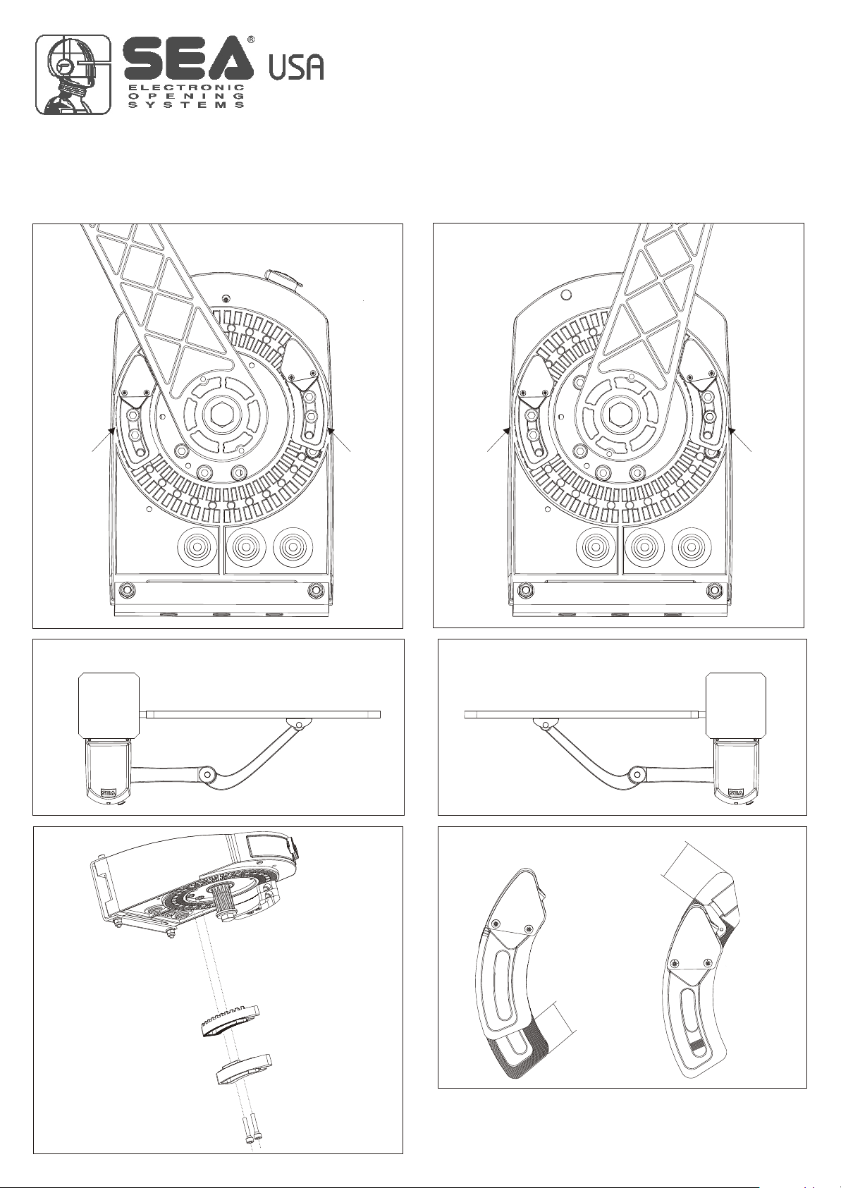
- The two articulated arms must be assembled differently, distinguishing the right arm from the left one.
See Fig. 11 and 12.
Note: Before inserting the pivots lubricate them with water repellent grease
ASSEMBLING OF THE ARTICULATED ARM
RIGHT HAND MOUNTING
LEFT HAND MOUNTING
PIVOTS
PIVOTS
International registered trademark n. 2.777.971
REV 00 - 03/2009 6

- Fit the articulated arm into the motor shaft and lock it with the special screws (Fig. 13).
- The protection cover must be mounted on the end of all adjustments.
Fig. 13
For further information see point “External release”.
EXTERNAL RELEASE MOUNTING
ATTACHMENT OF THE ARTICULATED ARM TO THE MOTOR
International registered trademark n. 2.777.971
REV 00 - 03/2009 7
Fig.14
Return spring

Fig. 17Fig. 16
Fig. 15
FIXING OF THE FRONT BRACKET
- Close the leaf completely
- Release the motor (see Fig. 18 e 19)
- Extend the articulated arm (Fig. 8), lean the adjustable front bracket on the gate and make two marks on the center of the two
holes (Fig. 15) respecting the measures in Fig. 8.
- Perforate the leaf and fix the front bracket with the screws (Fig. 16)
- Before tightening the screws move the front bracket to the right or to the left for a good positioning of the arm on the gate (Fig.
17) respecting the measure D in Fig. 8.
International registered trademark n. 2.777.971
REV 00 - 03/2009 8

Fig. 18 Fig. 19
To release operate as follows:
- Take off the protection cap of the lock.
- Insert the key and turn about 90° into clockwise direction (Fig. 18).
- Pull the door until its complete opening (Fig. 19).
- Open manually the leaf
To block again operate as follows:
- close the door again.
- Turn the key about 90° into anti-clockwise direction.
- Extract the key.
- Close the lock again with the protection cap.
90°
Operator locked Operator released
RELEASE SYSTEM
International registered trademark n. 2.777.971
REV 00 - 03/2009 9
- Release the operator.
- Open the leaf completely or up to the desired opening point.
- Position the stop as in Fig. 24 on the stop of the arm and lock the screws as in Fig. 25.
N.B: The delivered screws are selfthreading and have to be locked at 10 Nm.
RIGHT MOTOR
LEFT MOTOR
Closing OpeningOpening Closing
STOP STOP STOP STOP
Fig. 20 Fig. 21
Fig. 25
.0,4 inc
max
LEFTHAND MOUNTING RIGHTHAND MOUNTING
Fig. 22 Fig. 23
4 c0, in .
max
Fig. 24
MECHANICAL POSITIVE STOP ADJUSTMENT IN OPENING
International registered trademark n. 2.777.971
REV 00 - 03/2009 10

Fig. 26
PERIODICAL MAINTENANCE
Grease the moving parts
(Articulated arm, release, etc..)
Check the functioning of the release
Check the lock of the screws
Check the wear of the devices in movement
Check the integrity of the connected cables
Annual
Annual
Annual
Annual
Annual
RISK EXAMINATION
The points pointed by arrows in Fig. 26 are potentially
dangerous. The installer must take a close risk examination to
prevent crushing, conveying, cutting, grappling, trapping so to
guarantee a safe installation for people, things and animals
(
).
Re. Laws in force in the country where the installation has been
made
International registered trademark n. 2.777.971
REV 00 - 03/2009 11

RADIO RECEIVER
PHOTOCELLS
KEY SWITCH
FLIPPER ACCESSORIES
ELECTRIC LOCK
EXTERNAL
LOOP DETECTOR
FLASHING LAMP
TRANSMITTER KIT EXTERNAL LOCK
FLIPPER
SUPPORTS
FOR PHOTOCELLS
KIT LIMIT SWITCH
International registered trademark n. 2.777.971
REV 00 - 03/2009 12

International registered trademark n. 2.777.971
REV 00 - 03/2009
SAFETY PRECAUTIONS
Every change on trimmers and on dip switch must be done with the gate closed, or without
power supply.
All electrical installation work should conform to the current edition of the LEE Regulations
and all electrical work should only be carried out by a competent electrician. A 16A - 0,03A
differential switch must be incorporated into the mains electrical supply of the gates. Earth
bonding of the entire gate system must be correctly carried out.
To prevent mains interference all low voltage cabling (Push button, Photocell, Radio etc.)
should be run in separate cable ducts from main carrying cables.
Note: Use “cable clips” and/or “duct/box pipes” fitting close to the control panel box so to
protect the interconnection cables against pulling efforts.
SPARE PARTS
To obtain spare parts contact:
SEA USA Inc. 10850 N.W. 21st unit 160 DORAL MIAMI Florida (FL) 33172
Phone:++1-305.594.1151 Fax: ++1-305.594.7325 Toll Free: 800.689.4716
INTENDED USE
The USER 2 24V electronic control unit has been designed to be solely used as control unit
for the automation of swing gates.
LIMIT OF GUARANTEE
The USER 2 24V electronic control unit is guaranteed for a period of 24 months. The
guarantee period starts from the date stamp printed on the unit. The USER 2 24V guarantee
will be void if the unit has been incorrectly installed, not used for the intended purpose,
tampered with or modified in any way. The validity of this guarantee only extends to the
original purchaser of the unit.
NOTE: THE MANUFACTURER CAN NOT BE DEEMED RESPONSIBLE FOR ANY
DAMAGE OR INJURY CAUSED BY IMPROPER USE OF THIS PRODUCT.
13

MECHANICAL /
ELECTRONIC
LIMIT SWITCH
3131
3737
6262
7070
99
1313
6060
2323
6868
4343
3434
4949
2727
1212
1111
6565
6464
2828
1919
7474
3636
3939
7373
2121
2424
7575
1414
5252
5353
3030
4646
5959
33
11
1010
88
7979
3232
4040
4747
44
4545
22
4848
5757
6969
6666
6767
3838
2929
5050
2626
6363
77
1717
8383
5858
5454
7171
1515
8181
8282
7878
1818
4444
4242
7272
2222
2525
6161
7676
7777
2020
66
8080
3535
4141
3333
1616
1515
5656
5555
5151
55
2929 6680121166801211 SCREW TCCR M3X10 SEZ.TRILOB. ZNSCREW TCCR M3X10 SEZ.TRILOB. ZN
3030 6630161566301615 BATTERY CARD SUPPORTBATTERY CARD SUPPORT
3131 2302401523024015 USER 2 24V W/BOXUSER 2 24V W/BOX
3232 6630165566301655 COVER FOR ELECTR. CARD FLIPPERCOVER FOR ELECTR. CARD FLIPPER
3333 6680106766801067 SCREW AUT.TCCR 3,5X8 ZN UNI9707SCREW AUT.TCCR 3,5X8 ZN UNI9707
3434 6530237565302375 PIVOT FLIPPERPIVOT FLIPPER
3535 6680154266801542 ELAST. FIXING W./CALOTTE D.5ELAST. FIXING W./CALOTTE D.5
3636 6600131566001315 PIN RELEASE FLIPPERPIN RELEASE FLIPPER
3737 5470110554701105
CONNECTOR 3 WAYS+FUSE SUPPORTCONNECTOR 3 WAYS+FUSE SUPPORT
3838 6680113466801134 SCREW TCCR 2.9X19 ZINC. UNI6954SCREW TCCR 2.9X19 ZINC. UNI6954
3939 6600132066001320 PIN BALL RELEASE FLIPPERPIN BALL RELEASE FLIPPER
4040 6640103566401035 SPRING D.8 L.46 F.1,1 SP.15 ORSPRING D.8 L.46 F.1,1 SP.15 OR
4141 6680154166801541 ELASTIC. FIXING W/CALOTTE D.4ELASTIC. FIXING W/CALOTTE D.4
4242 6680603966806039 PIN CyLIND. 5X32 UNI6364-APIN CyLIND. 5X32 UNI6364-A
4343 6530237065302370
ROD FLIPPERROD FLIPPER
4444 6680602166806021 PIN CYL. 4X28 UNI6364-APIN CYL. 4X28 UNI6364-A
4545 6640119066401190 SPRING FLIPPERSPRING FLIPPER
4646 6630162066301620 EXTERNAL RELEASE FLIPPEREXTERNAL RELEASE FLIPPER
4747 6640118066401180
SPRING EXTERNAL RELEASE FLIPPERSPRING EXTERNAL RELEASE FLIPPER
4848 6650101466501014 BEARING 16003 2ZBEARING 16003 2Z
4949 6530238065302380 FRAME CAP FLIPPERFRAME CAP FLIPPER
5050 6680126166801261 SCREW TCEI M6X95 8.8 ZINCATASCREW TCEI M6X95 8.8 ZINCATA
5151 5420010054200100 TRANSFOR.110VTRANSFOR.110V
5252 6630111166301111 LOGO SEA FOR FLIPPER (ABS)LOGO SEA FOR FLIPPER (ABS)
5353 6630161066301610 CARTER FLIPPERCARTER FLIPPER
5454 6680103766801037 SCREW AUT.TCCR3X10 ZINC.UNI9707SCREW AUT.TCCR3X10 ZINC.UNI9707
5555 6680156366801563 SCREW TCCR M5X20 ZN UNI8112SCREW TCCR M5X20 ZN UNI8112
5656 -------------- --------------
5757 6650106566501065 BEARING 6205 2ZBEARING 6205 2Z
5858 6680137366801373 V.TSPCR M4X10NIC SZ.TR.UNI8113V.TSPCR M4X10NIC SZ.TR.UNI8113
5959 6630162566301625 EXTERNAL RELEASE PLATEEXTERNAL RELEASE PLATE
6060 6530235565302355 BASE FLIPPERBASE FLIPPER
6161 6700122567001225 SEAL.PARAOIL 25X35X5 TYPE GPSEAL.PARAOIL 25X35X5 TYPE GP
6262 5470111554701115 CABLE PRESS SR 2M-1 NYLONCABLE PRESS SR 2M-1 NYLON
6363 6680124166801241 SCREW TCEI M6X20 ZN SEC.TRILOB.SCREW TCEI M6X20 ZN SEC.TRILOB.
6464 6530240565302405
STOP HANDLE SX FLIPPERSTOP HANDLE SX FLIPPER
6565 6530240065302400 STOP HANDLE B SX FLIPPERSTOP HANDLE B SX FLIPPER
6666 6670011066700110 LOCK D.15 RELEASE PLUSLOCK D.15 RELEASE PLUS
6767 6670012166700121 TCAP LOCK COVER RELEASE PLUSTCAP LOCK COVER RELEASE PLUS
6868 6530236565302365 RELEASE LEVER FLIPPERRELEASE LEVER FLIPPER
6969 6670001566700015
TONGUE WITH HOLE FOR LOCK LEPUSTONGUE WITH HOLE FOR LOCK LEPUS
7070 5471015054710150
MICRO OMRON V-163-1A6/LONG. LEVERMICRO OMRON V-163-1A6/LONG. LEVER
7171 6680154966801549 SCREW TCCR AUT3X18 UNI9707 ZNSCREW TCCR AUT3X18 UNI9707 ZN
7272 6681000066810000 PIN 2X12 UNI1336PIN 2X12 UNI1336
7373 6600132566001325 PIN D.6X50 X RELEASE LEVERPIN D.6X50 X RELEASE LEVER
7474 6600131066001310 PIVOT ARM FLIPPERPIVOT ARM FLIPPER
7575 6620096066200960 BRACKET ARM/GATEBRACKET ARM/GATE
7676 65302345L65302345L
CURVED ARM FLIPPER LAV.CURVED ARM FLIPPER LAV.
7777 65302350L65302350L STRAIGHT ARM FLIPPER LAV.STRAIGHT ARM FLIPPER LAV.
7878 6680500566805005 SEEGER EST.D.12 GALV.SEEGER EST.D.12 GALV.
7979 6630165066301650 COVER ARTICULATED ARM FLIPPERCOVER ARTICULATED ARM FLIPPER
8080 6680153766801537 SCREW TCCR M4X10 ZN SEC.TRILOB.SCREW TCCR M4X10 ZN SEC.TRILOB.
8181 6680401966804019 WASHER P.10,5X30X2,5 UNI6593 ZNWASHER P.10,5X30X2,5 UNI6593 ZN
8282 6680415066804150
ELAST. WASHER M10 TIPOA UNI8840 ZNELAST. WASHER M10 TIPOA UNI8840 ZN
8383 6680129566801295 SCREW TE TE M 10 X20 GALV.SCREW TE TE M 10 X20 GALV.
11
6630163566301635 CAP FLIPPERCAP FLIPPER
226640119566401195 SPRING CAP FLIPPERSPRING CAP FLIPPER
336630163066301630 PUSHBUTTON MICRO INTERRUPTERPUSHBUTTON MICRO INTERRUPTER
446640118566401185
SPRING PUSHBUTTON MICRO FLIPPERSPRING PUSHBUTTON MICRO FLIPPER
556680123866801238
SCREW TCEI M6X30 ZN SEZ.THREELOB.SCREW TCEI M6X30 ZN SEZ.THREELOB.
666680105566801055
SELFCUT. SCREW TC CR. 2,2X13 NICH.SELFCUT. SCREW TC CR. 2,2X13 NICH.
776620163566201635 PLATE MICRO STOP FLIPP.PLATE MICRO STOP FLIPP.
886630164566301645 SEMISHELL INF. MICRO FLIPPERSEMISHELL INF. MICRO FLIPPER
995471015854710158 MICROINT. AH1662 X FLIPPERMICROINT. AH1662 X FLIPPER
1010 6630164066301640 SEMISHELL UP. MICRO FLIPPERSEMISHELL UP. MICRO FLIPPER
1111 6530239565302395 STOP ROD B DX FLIPPERSTOP ROD B DX FLIPPER
1212 6530239065302390 STOP ROD FLIPPER DXSTOP ROD FLIPPER DX
1313 5471018054710180 CABLE PASSAGE IN PVC D. 20CABLE PASSAGE IN PVC D. 20
1414 6620153566201535 FIXING PLATE FLIPPERFIXING PLATE FLIPPER
1515 6680300666803006 SELFLOCKING NUT HIGH M6 GALV.SELFLOCKING NUT HIGH M6 GALV.
1616 6680403566804035 WASHER P.6,4X12,5X1,6 UNI6592 ZNWASHER P.6,4X12,5X1,6 UNI6592 ZN
1717 6680124966801249 SCREW TCEI M6X100 GALV.SCREW TCEI M6X100 GALV.
1818 6680502566805025 SEEGER EST.D.25 ZNSEEGER EST.D.25 ZN
1919 6600122666001226 SLOW SHAFT FLIPPERSLOW SHAFT FLIPPER
2020 6680412566804125 CUTTING RING 34,5X25,15X0,3CUTTING RING 34,5X25,15X0,3
2121 6610237566102375 WHEEL Z40 ARM PROWHEEL Z40 ARM PRO
2222 6681003666810036 BALL DIAMETER 10 UNI100 Cr6BALL DIAMETER 10 UNI100 Cr6
2323 6530236065302360 FRAME FLIPPERFRAME FLIPPER
2424 6610238066102380 ENDLESS SCREW M1,5 FLIPPERENDLESS SCREW M1,5 FLIPPER
2525 6700016567000165 SEAL OR 2125(31,47X1,78)VITONSEAL OR 2125(31,47X1,78)VITON
2626 6680124066801240 SCREW TCEI M6X20 8.8 GALV.SCREW TCEI M6X20 8.8 GALV.
2727 6530238565302385 MOTOR FLANGE FLIPPERMOTOR FLANGE FLIPPER
2828 6580224665802246 MOTOREDUCER FLIPPER 11NMMOTOREDUCER FLIPPER 11NM
14


SEA USA Inc.
10850 N.W. 21st unit 160 DORAL MIAMI
Florida (FL) 33172
Phone:++1-305.594.1151 Fax: ++1-305.594.7325
Toll Free: 800.689.4716
International registered trademark n. 2.777.971
Table of contents
Other SEA Gate Opener manuals


SEA
SEA full tank User manual

SEA
SEA EASY 20 User manual

SEA
SEA COMPACT 200 CP Instruction manual

SEA
SEA 1110 User manual

SEA
SEA ORION BOX 24V User manual

SEA
SEA TAURUS BOX 1000 User manual

SEA
SEA SUPER FULL TANK 20 G6 380V User manual

SEA
SEA JOINT Original instructions

SEA
SEA TORG Instruction manual

SEA
SEA ARM Instruction manual


Popular Gate Opener manuals by other brands

On Automation
On Automation Crono SL600.24 instruction manual

Palfinger
Palfinger Minifix K1Plus Series troubleshooting guide

JOYTECH
JOYTECH PY500AC user manual

Viking
Viking X-390 installation instructions

Centurion
Centurion D5-EVO REPAIR Programming manual

Pujol
Pujol Radius Installation and adjustment instructions


