SEA TAURUS BOX 1000 User manual


IMPORTANT SAFETY INFORMATION
All the above described operations must be made exclusively by an authorized installer
Clean and grease parts in movement (wheels,
counter-connecting rod, release, etc.)
Check for corroded parts and replace if
necessary
Check if the screws and all mounting
hardwares are properly tighten
Annual
Annual
Annual
Check the conditions of wear and tear of the
devices in movement
Check the correct drain of the rainwater
Check the integrity of the connection cables
Annual
Annual
Annual
Inspect the track for any signs of cracking or
separation
Ensure that the gate moves freely
Annual
Annual
Check and confirm the proper operation of all
safety devices (photocells, edge sensors etc)
Check and confirm the operation of all
installed accessories
Check and confirm the operation of the
manual release
Annual
Annual
Annual
TURNING ON THE POWER
Check the battery conditions and be sure that
connections are free of corrosion
Verify the functionally of the battery backup,
or power failure option
BY MAIN POWER SOURCE TURNED OFF
Annual
TURNING OFF THE POWER
CCCC
GENERAL SAFETY PRECAUTIONS
The following precautions are an integral and essential part of the product and must be supplied to the user Read
them carefully as they contain important indications for the safe installation, use and maintenance.
1. These instruction must be kept and forwarded to all possible future users of the system.
2. This product must be used only for that which it has been expressly designed.
3. Any other use is to be considered improper and therefore dangerous.
4. The manufacturer cannot be held responsible for possible damage caused by improper, erroneous or
unreasonable use.
5. Avoid operating in the proximity of the hinges or moving mechanical parts.
6. Do not enter the path of the moving gate while in motion.
7. Do not obstruct the motion of the gate as this may cause a situation of danger.
8. Do not allow children to play or stay within the path of the moving gate.
9. Keep remote control or any other control devices out of the reach of children, in order to avoid possible involuntary
activation of the gate operator.
10. In case of break down or malfunctioning of the product, disconnect from the main power source.
Do not attempt to repair or intervene directly, contact only qualified personnel for repair.
11. Failure to comply with the above may create a situation of danger.
12. All cleaning, maintenance or repair work must be carried out by qualified personnel.
13. In order to guarantee that the system works efficiently and correctly it is important to have the manufacturer's
instructions on maintenance of the gate and operator carried out by qualified personnel.
14. In particular, regular checks are recommended in order to verify that the safety devices are operating correctly.
All installation, maintenance and repair work must be documented and made available to the user.
IMPORTANT SAFETY INSTRUCTIONS
WARNING – To reduce the risk of injury or death:
1. READ AND FOLLOW ALL INSTRUCTIONS.
2. Never let children operate or play with gate controls. Keep the remote control away from children.
3. Always keep people and objects away from the gate. NO ONE SHOULD CROSS THE PATH OF THE MOVING GATE.
4.Test the gate operator monthly. The gate MUST reverse on contact with a rigid object or stop when an object
activates the non-contact sensors. After adjusting the force or the limit of travel, retest the gate operator. Failure to
adjust and retest the gate operator properly can increase the risk of injury or death.
5. Use the emergency release only when the gate is not moving
6. KEEP GATES PROPERLY MAINTAINED. Read the owner’s manual. Have a qualified service person make
repairs to gate hardware.
7. The entrance is for vehicles only. Pedestrians must use separate entrance.
8. Every gate operator installation MUST have secondary protection devices agains entrapments, such as edge
sensors and photo beams more in particulary in places where the risk of entrapments is more likely to occur
9. SAVE THESE INSTRUCTIONS
!
PERIODICAL MAINTENANCE

GENERAL SAFETY INFORMATION
An appliance shall be provided with an instruction manual. The instruction manual shall give instructions for the
installation, operation, and user maintenance of the appliance.
The installation instructions shall specify the need for a grounding-type receptacle for connection to the supply and
shall stress the importance of proper grounding.
The installation instructions shall inform the installer that permanent wiring is to be employed as required by local
codes, and instructions for conversion to permanent wiring shall be supplied.
Information shall be supplied with a gate operator for:
a) The required installation and adjustment of all devices and systems to effect the primary and secondary protection
against entrapment (where included with the operator).
b) The intended connections for all devices and systems to effect the primary and secondary protection against
entrapment. The information shall be supplied in the instruction manual, wiring diagrams, separate instructions, or the
equivalent.
Vehicular gate operators (or systems)
A vehicular gate operator shall be provided with the information in the instruction manual that defines the different
vehicular gate operator Class categories and give examples of each usage. The manual shall also indicate the use for
which the particular unit is intended as defined in Glossary, Section 3. The installation instructions for vehicular gate
operators shall include information on the Types of gate for which the gate operator is intended.
A gate operator shall be provided with the specific instructions describing all user adjustments required for proper
operation of the gate. Detailed instructions shall be provided regarding user adjustment of any clutch or pressure relief
adjustments provided. The instructions shall also indicate the need for periodic checking and adjustment by a qualified
technician of the control mechanism for force, speed, and sensitivity.
Instructions for the installation, adjustment, and wiring of external controls and devices serving as required protection
against entrapment shall be provided with the operator when such controls are shipped with the operator.
Instructions regarding intended installation of the gate operator shall be supplied as part of the installation instructions
or as a separate document. The following instructions or the equivalent shall be supplied where applicable:
IMPORTANT INSTALLATION INSTRUCTIONS
a) Install the gate operator only when:
1) The operator is appropriate for the construction of the gate and the usage Class of the gate,
2) All openings of a horizontal slide gate are guarded or screened from the bottom of the gate to a minimum of 4 feet
(1.22 m) above the ground to prevent a 2-1/4 inch (57.2 mm) diameter sphere from passing through the openings
anywhere in the gate, and in that portion of the adjacent fence that the gate covers in the open position,
3) All exposed pinch points are eliminated or guarded, and
4) Guarding is supplied for exposed rollers.
b) The operator is intended for installation only on gates used for vehicles. Pedestrians must be supplied with a
separate access opening. The partial access opening shall be designed to promote pedestrian usage. Locate the gate
such that persons will not come in contact with the vehicular gate during the entire path of travel of the vehicular gate.
c) The gate must be installed in a location so that enough clearance is supplied between the gate and adjacent
structures when opening and closing to reduce the risk of entrapment. Swinging gates shall not open into public access
areas.
d) The gate must be properly installed and work freely in both directions prior to the installation of the gate operator. Do
not over-tighten the operator clutch or pressure relief valve to compensate for a damaged gate.
e) The gate operator controls must be placed so that the user has full view of the gate area when the gate is moving and
AWAY FROM THE GATE PATH PERIMETER.
f) Controls intended for user activation must be located at least six feet (6’) away from any moving part of the gate and
where the user is prevented from reaching over, under, around or through the gate to operate the controls. Outdoor or
easily accessible controls shall have a security feature to prevent unauthorized use.
g) The Stop and/or Reset button must be located in the line-of-sight of the gate. Activation of the reset control shall not
cause the operator to start.
h) A minimum of two (2) WARNING SIGNS shall be installed, one on each side of the gate where easily visible

i) For gate operators utilizing a non-contact sensor:
1) See instructions on the placement of non-contact sensors for each Type of application
2) Care shall be exercised to reduce the risk of nuisance tripping, such as when a vehicle, trips the sensor while the
gate is still moving
3) One or more non-contact sensors shall be located where the risk of entrapment or obstruction exists, such as the
perimeter reachable by a moving gate or barrier
j) For a gate operator utilizing a contact sensor:
1) One or more contact sensors shall be located where the risk of entrapment or obstruction exists, such as at the
leading edge, trailing edge, and postmounted both inside and outside of a vehicular horizontal slide gate.
2) One or more contact sensors shall be located at the bottom edge of a vehicular vertical lift gate.
3) One or more contact sensors shall be located at the pinch point of a vehicular vertical pivot gate.
4) A hardwired contact sensor shall be located and its wiring arranged so that the communication between the
sensor and the gate operator is not subjected to mechanical damage.
5) A wireless contact sensor such as one that transmits radio frequency (RF) signals to the gate operator for
entrapment protection functions shall be located where the transmission of the signals are not obstructed or
impeded by building structures, natural landscaping or similar obstruction. A wireless contact sensor shall
function under the intended end-use conditions.
6) One or more contact sensors shall be located on the inside and outside leading edge of a swing gate. Additionally,
if the bottom edge of a swing gate is greater than 6 inches (152 mm) above the ground at any point in its arc of
travel, one or more contact sensors shall be located on the bottom edge.
7) One or more contact sensors shall be located at the bottom edge of a vertical barrier (arm).
Instruction regarding intended operation of the gate operator shall be provided as part of the user instructions or as a
separate document. The following instructions or the equivalent shall be provided
NOTICE
As for misunderstandings that may arise refer to your area distributor or call our help desk. These instructions are part
of the device and must be kept in a well known place. The installer shall follow the provided instructions thoroughly.
SEA products must only be used to automate doors, gates and wings. Any initiative taken without SEA USA Inc. explicit
authorization will preserve the manufacturer from whatsoever responsibility. The installer shall provide warning notices
on not assessable further risks. SEA USA Inc. in its relentless aim to improve the products, is allowed to make
whatsoever adjustment without giving notice. This doesn’t oblige SEA to up-grade the past production. SEA USA Inc.
can not be deemed responsible for any damage or accident caused by product breaking, being damages or accidents
due to a failure to comply with the instructions herein. The guarantee will be void and the manufacturer responsibility
will be nullified if SEA USA Inc. original spare parts are not being used. The electrical installation shall be carried out by
a professional technician who will release documentation as requested by the laws in force. Packaging materials such
as plastic bags, foam polystyrene, nails etc must be kept out of children’s reach as dangers may arise.
To respect the norms in force it is recommended to use the ENCODER SYSTEM together with the electronic
control units
Starting on Jan. 12, 2016, new UL 325 changes take effect, bringing a series of new mandates for the gate operator
industry. Here’s a quick guide to the key modifications.
1. Entrapment-Protection Devices. Gate operators are required to have a minimum of two independent means of
entrapment protection where the risk of entrapment or obstruction exists. A manufacturer can use two inherent-type
systems, two external-type systems, or an inherent and an external system to meet the requirement. However, the
same type of device cannot be used for both means of protection.
2. Monitoring Required. An external non-contact sensor or contact sensor may be used as a means of entrapment
protection. However, the sensor must be monitored once every cycle for (1) the correct connection to the operator and
(2) the correct operation of the sensor.
If the device is not present, not functioning, or is shorted, then the gate operator can only be operated by constant
pressure on the control device. Portable wireless controls will not function in this case.
3. Entrapment Risk Identification. As in the past, it’s up to the installer to examine the installation and determine
where a risk of entrapment or obstruction exists. Manufacturers are required to provide instructions for the placement
of external devices, but they give only examples of suggested entrapment protection in their installation manuals. If the
installer identifies a risk of entrapment or obstruction, at least two independent means of entrapment protection are
required.
4.Terminology Change. The terms “primary” and “secondary” have been removed in the description of entrapment
protection devices. This was done to emphasize that all entrapment protection devices are equally important.
Changes to UL 325 ED. 6th for Gate Operators

5. The End of Type E. Type E (audible alarm) devices can no longer be used for entrapment protection. This change
was made because the Type E device is really a warning device, not an entrapment-protection device. Also, all gate
operator classes are now required to have an audio alarm that sounds when two successive obstructions are
encountered via a contact-type system.
6. Access Control Location for Emergency Use. An exception has been added in the manufacturer’s instructional
requirements for the location of controls that operate the gate.
The instructional requirements state that these controls must be at least 6' away from any moving part of the gate. In the
new exception, “Emergency access controls only accessible by authorized personnel (e.g., fire, police, EMS) may be
placed at any location in the line-of-sight of the gate.”
7. Barrier-Arm Operator Exception. An exception has changed for barrier-arm gate operators requiring entrapment
protection. The previous exception stated that a barrier-arm operator did not require entrapment protection if the arm
did not move toward a rigid object closer than 2'. The distance has been reduced to 16" so it more closely aligns with the
industry-defined entrapment protection provisions in ASTM F2200.
8. Gate Operator Class II and Class III Definitions. The definitions for installation classes for gate operators were
modified. Class II now includes commercial locations accessible to the general public. Class III was refined to specify
industrial locations not accessible to the general public. These changes, while seemingly minor, may affect which gate
operator is suitable for a particular installation location.
UL 325 ED. 6th ENTRAPMENT PROTECTION REQUIREMENTS
This vehicular gate operator must be installed with at least two independent entrapment protection
means as specified in the table below.
VERITICAL BARRIER NOTE:
Barrier gate operators (arm) that is not intended to move toward a rigid objact closer than 16 inches (406mm)
are not required to be provided with a means of entrapment protection
* B1 and B2 means of entrapment protection MUST be MONITORED
HORIZONTAL SLIDE
VERTICAL LIFT - VERTICAL PIVOT
ENTRAPMENT
PROTECTION
TYPES
TYPE A
TYPE B1
TYPE B2
TYPE C
Inherent entrapment protection system
Non-contact sensors such as photoelectric sensors or equivalents
Contact sensors such as edge sensors or equivalent devices
Inherent force limiting, inherent adjustable clutch or inherent pressure relief device
The same type of device shall not be used for both entrapment protection means. Use of a single device to cover both
the opening and closing directions is in accordance with the requirement; however, a single device is not required to
cover both directions. Tice installer is required to install entrapment protection devices in each entrapment zone
TYPE D Actuating device requiring constant pressure to maintain opening or closing motion of the gate
SWING
VERTICAL BARRIER (ARM)
A , B1*, B2* or D A , B1*, B2*, C or D
GATE OPERATOR CATEGORY
Effective January, 12 2016
VEHICULAR GATE OPERATOR CLASSES
Residential Vehicular Gate Operator-Class I: A vehicular gate operator (or system) intended for use in garages or
parking areas associated with a residence of one-to-four single families
Commercial/General Access Vehicular Gate Operator-Class II: A vehicular gate operator (or system) intended for
use in a commercial location or building such as a multi-family housing unit (five or more single family units), hotel,
garages, retail store, or other buildings accessible by or servicing the general public
Industrial/Limited Access Vehicular Gate Operator–Class III: A vehicular gate operator (or system) intended for
use in an industrial location or building such as a factory or loading dock area or other locations not accessible by or
intended to service the general public
Restricted Access Vehicular Gate Operator–Class IV: A vehicular gate operator (or system) intended for use in an
industrial location or building such as a factory or loading dock area or other locations not accessible by or intended to
service the general public
6
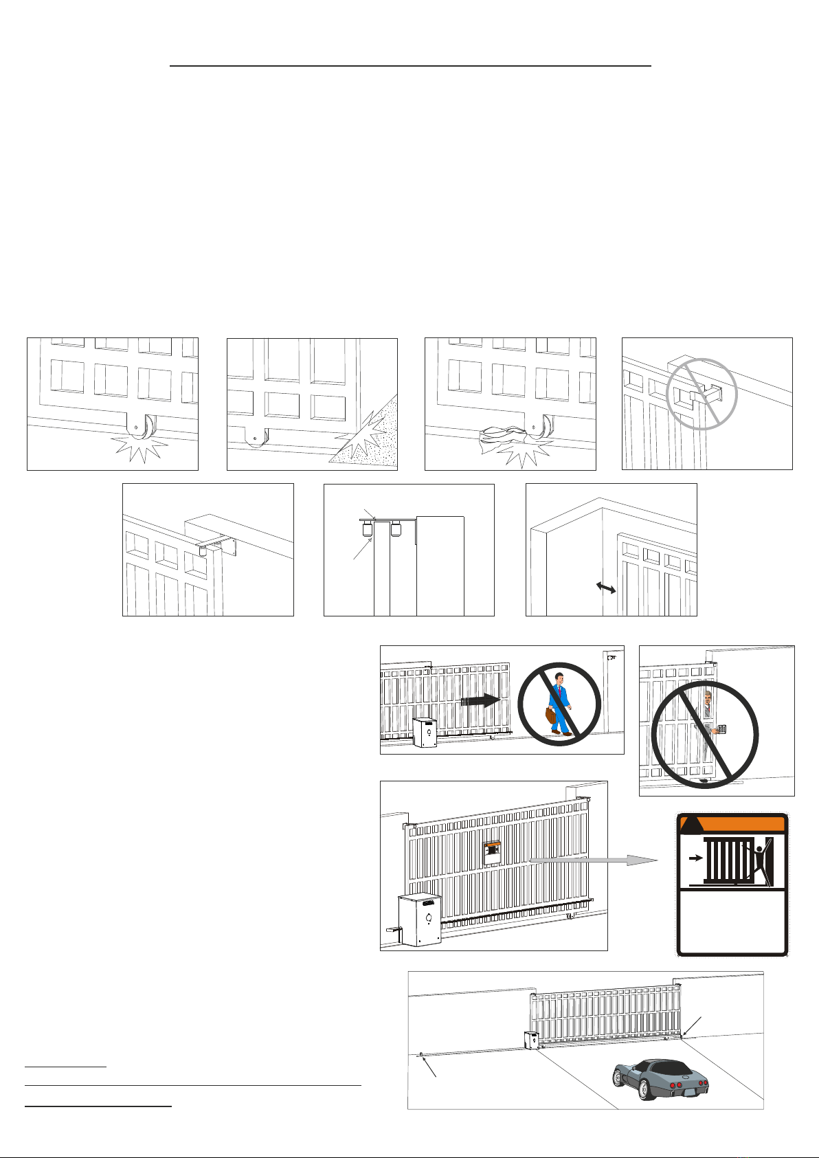
PRECAUTIONS
SEA operators have been created for the
automation of gates used by vehicles only. Be
aware to avoid the crossing of the gate path
because it is very dangerous for pedestrians
(fig.8).
Make sure that no person could activate the
automation or act on it from the outside (fig. 9)
WARNING SIGNS
Install the warning signs, on each side of the
gate and in a visible zone which informs the
pedestrians about the danger they run when
passing or resting in the environment of the gate
Important:
For a higher security, SEA advices to install
infrared photocells
Fig. 1
Fig. 2
Fig. 3 Fig. 4
Fig. 5 Fig. 6
1/2”
1/4”
5”
Fig. 7
!
WARNING
Moving Gate Can Cause
Serious Injury Or Death
- KEEP CLEAR ! Gate may move at any
time without prior Warning.
- Do not let children operate the gate or
play in the gate area.
- This entrance is for vehicle only.
Pedestrians must use separate entrance
TYPE OF INSTALLATION
A front installation is the right and only
possible installation, it is highly recommended
to install two security gate stops on the two
extremities of the rail to prevent the gate from
derailment (fig. 11).
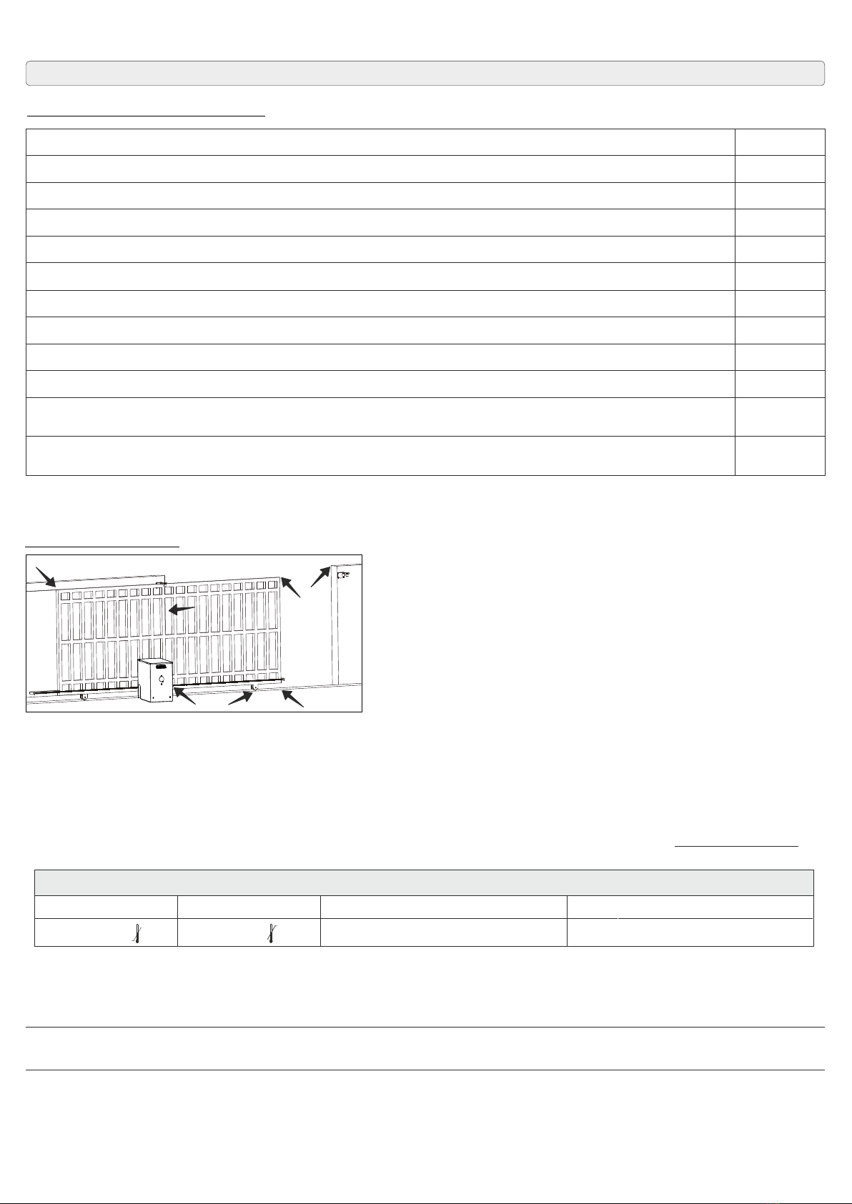
GATE ARRANGEMENT
The first thing to check is that the gate is in good running order as follows:
a) The gate is rigid and straight and runs smoothly throughout its travel.
b) That the inferior sliding guide-rail is perfectly straight and horizontal to avoid a derailment of the gate (fig.
1); furthermore it must be free of irregularities and foreign bodies which could obstruct the normal run of the
gate (fig. 2 - 3).
c) That the upper guides are not fixed (fig. 4) but furnished with rollers
d) That the distance between the end of the gate (in maximum opening position) and the eventual wall must
be at least of 5 inches (fig. 7) which allow the sliding of the gate without difficulties (fig. 5 and 6).
e) The lower support wheels have sealed bearings or grease points.
f) The top guide must be manufactured and installed so that the gate is perfectly upright.
g) Physical gate stops must be fitted to prevent the gate coming out of its guides and track.
Fig. 8
GATE WARNINGS AND PRECAUTIONS
Fig. 9
Fig. 10
!
WARNING
Moving Gate Can Cause
Serious Injury Or Death
- KEEP CLEAR ! Gate may move at any time
without prior Warning.
- Do not let children operate the gate or play in
the gate area.
- This entrance is for vehicle only.
Pedestrians must use separate entrance
Fig. 11
Over-Travel Stop
Over-Travel
Stop
7
20.7”
13.6”
12.8”
V (±5%) 50/60 Hz120
350W
3,2 A
15 Nm
60 µF
11 In/s
30 %
integrated
1000 Lb
16,4 ft
electromechanical
from -4°F to 131°F
73 lb
IP 55
I II III IV
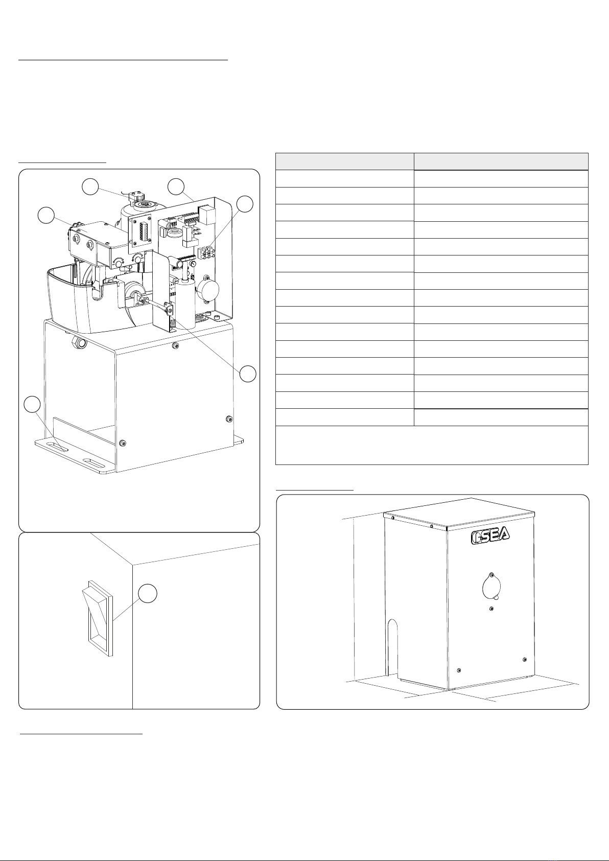
1. FEATURES AND SPECIFICATIONS
TAURUS BOX is an electro-mechanical reduction operator. The TAURUS BOX can be supplied with either
mechanical clutch or electronic sensing device as methods of limiting the motor torque. The gates open &
close stop limits are accurately stored by mechanically triggering the on-board micro-switch. Manual release
is quickly achieved by operating a key manual release system.The control unit allows to choose between
automatic or semi-automatic control logic and will provide all normal safety logic functions
TECHNICAL FEATURES
Power supply
Power
Absorbed current
Thrust force
Capacitor
Leaf speed (pinion Z17)
Use rate
Thermal protection
Max gate weight
Max gate opening
Type of limit switch
Operating temperatures
Operator weight
Protection class
Classification
TAURUS BOX 1000 FAST
1
2
3
4
5
6
NOTE: The frequency of use is valid only for the first
hour at 68° F room temperature
2. GENERAL SWITCH
Into TAURUS BOX you can find a general switch (Fig. 13) which allows to turn on or off the electric power
supply. This switch must be set on «I» to start the operator
CAUTION: Operator must be started only after having correctly installed and adjusted all components
WARNING! It is mandatory to switch off the power supply by putting switch to «O» when you need to work on
the operator (eg. repairs, power loss, components installation).
COMPONENTS
DIMENSIONS
6
Fig. 12
Fig. 13
Fig. 14
1 Release
2 Magnetic encoder
3 Limit switch
4 Foundation plate
5 Control unit
6 General switch

8
1
2
3
4
5
7
11
10
FREE EXIT LOOP
SAFETY LOOP
SAFETY EXIT
LOOP
6
6
8
8
9
Fig. 15
Travel Gate Stop
Travel Gate
Stop
A front installation is the right and only possible installation, it is highly recommended to install two travel gate
stops on the two extremities of the rail to prevent the gate from derailment (Fig. 16)
4. TYPE OF INSTALLATION
3. TYPICAL INSTALLATION
1) Operator
2) Concrete to build operator on
3) Photocells
4) Safety edge
5) Key switch
6) Travel gate stops
7) Radio receiver
8) Guide rollers
9) High speed ball bearing wheels
10) Warning notice inside
11) Warning notice outside
Fig. 16
WARNING: Only for vehicles access, pedestrians MUST have separate entrance
Install the operator always inside the property.
Always install travel gate stops on both ends of the gate.

9
Fig. 17
Fig. 18
Fig. 19
5.1. Arrange a little square of concrete with a perfect levelling on which the motor reducer will be fixed with the
special plugs (sizes on Fig. 19)
5.2. Make sure that in the center of the concrete pad has been forseen an exit for a sufficient number of pipes
(for all accessories like loop detectors, maglock, photobeam and others)
5.3. Before piercing the concrete square for the fixation of the motor reducer, make sure that the distance
between the centre of the oblong and the gate is of 3” (Fig. 19)
5.4. All openings of a horizontal slide gate are guarded or screened from the bottom of the gate to a minimum
of 4 feet (1,22 m) above the ground to prevent a 2-1/2 inch (57,2 mm) diameter sphere from passing through
the openings anywhere in the gate, and in that portion of the adjacent fence that the gate covers in open
position
5.5. Follow the local building code to determine the required depth of the concrete pad.
5.6. SEA recommend the following pad measurements:
5. CONCRETE PADS
6. GATE OPERATOR ATTACHMENT
6.1. Before starting the installation of the gate operator, make sure that the gate, the support wheels and the
guides are in optimal conditions, there is no impediments on the path of the gate and sufficient space
between the gate and the adjacent walls.
6.2. The operator and the gate MUST be level and parallel.
6.3. Attach the operator on the prepared pad using Red Head ½” x 3 ½” Anchors (Fig. 18)
Red Head
Fastener
½” x 3 ½”
Fig. 20 Fig. 21
MECHANICAL INSTALLATION
3”
16”
27”
Concrete
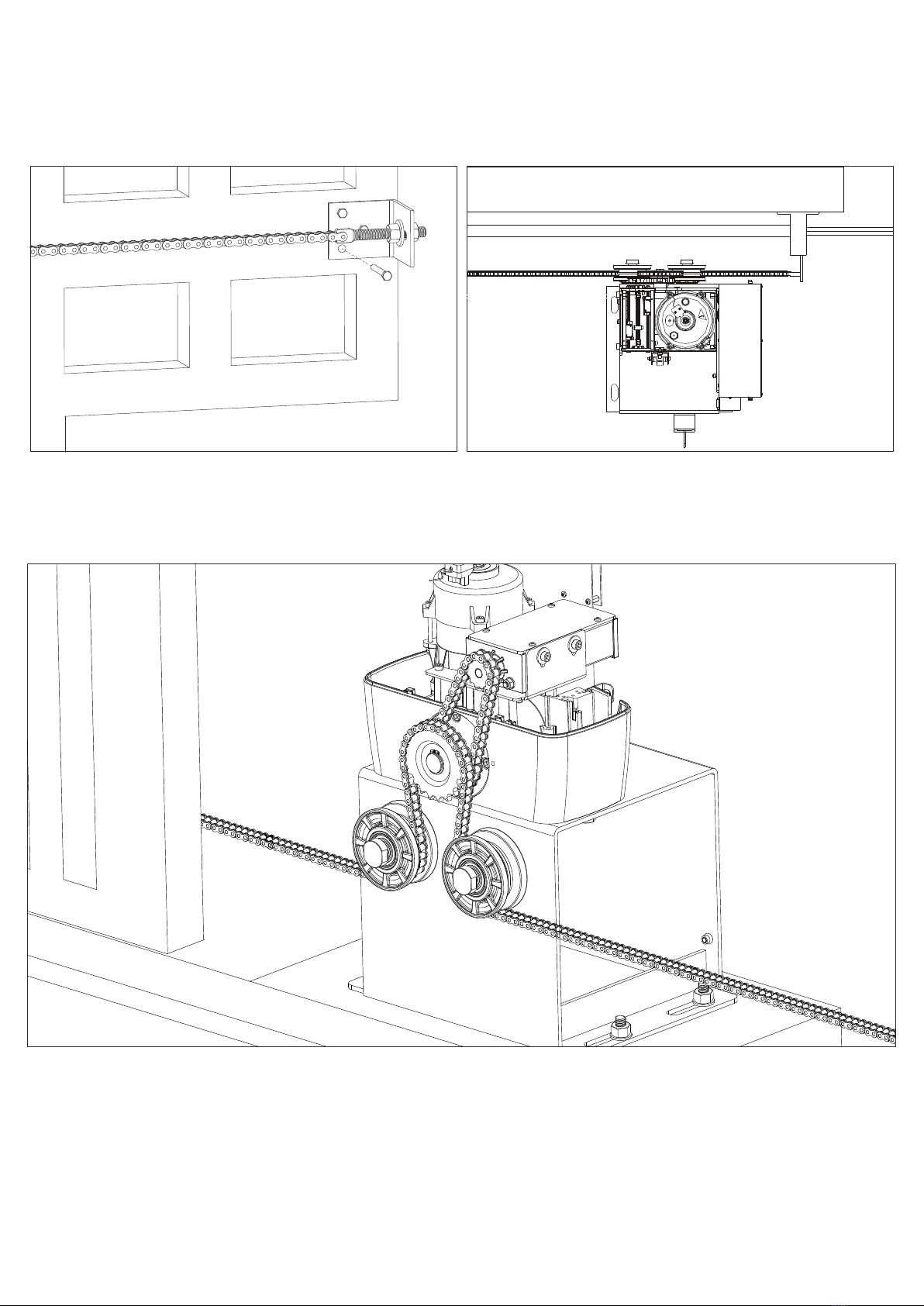
In Fig. 20 and Fig. 21 it is possible to see the correct installation with open and closed gate respectively;
notice the obliged run of the chain inside the pinion group which must not be modified.
Open position Closed position
7. CHAIN INSTALLATION
10
For a correct installation follow carefully the indications below:
7.1. Fix the angle irons with screws (not supplied), to the two extremities of the gate and fix the chain with the
provided tie rod (Fig. 22)
Fig. 22 Fig. 23
7.2. Install the chain making it pass through the pinion group as in Fig. 24.
The chain must be always in line both vertically and orizontally, if not perfectly aligned (Fig. 25 and Fig. 26) it
may derail from the pinion group or the motor reducer risks a greater effort not allowing the right operating of
the system.
Fig. 24

11
7.3. Install a fillet chain tensioner to two extremity of the gate to regulate the tension of the chain.
NOTE:
Execute this last operation with motor completely released using the provided special release key
Fig. 25 Fig. 26
Fig. 27 Fig. 28 Fig. 29
8. LIMIT SWITCH SETUP
8.1. Remove the operator cover.
8.2. The main power (120V) MUST be disconnected.
8Before acting on the limit switch, make sure that the operator chain is correctly attached to the gate, that .3.
limit switch cursor is in the central position of its run (Fig. 27) and the gate is in its half run.
Do not open To set or adjust the limit switch act only on the external screw. the limit switch casing
8.4. To install and adjust the limit switches in opening:
- release the operator
- open the gate manually
- act on the adjusting screw so that the microswitch can activate the contact with the cursor (Fig. 28)
8.5. To install and adjust the limit switches in closing:
- release the operator
- close the gate manually
- act on the adjusting screw so that the microswitch can activate the contact with the cursor (Fig. 29)
For a more accurate adjustment, act on the adjusting screws during the testing phase with AC power and
after having executed the previous operations.
NOTE: to adjust the movement directions, refer to the control unit instruction.
For limit switch connection see the electronic installation
CURSOR
ADJUSTING SCREWS ADJUSTING SCREWS
OPENING CLOSING
CURSOR CURSOR
MICRO
SWITCH MICRO
SWITCH
12
PGN
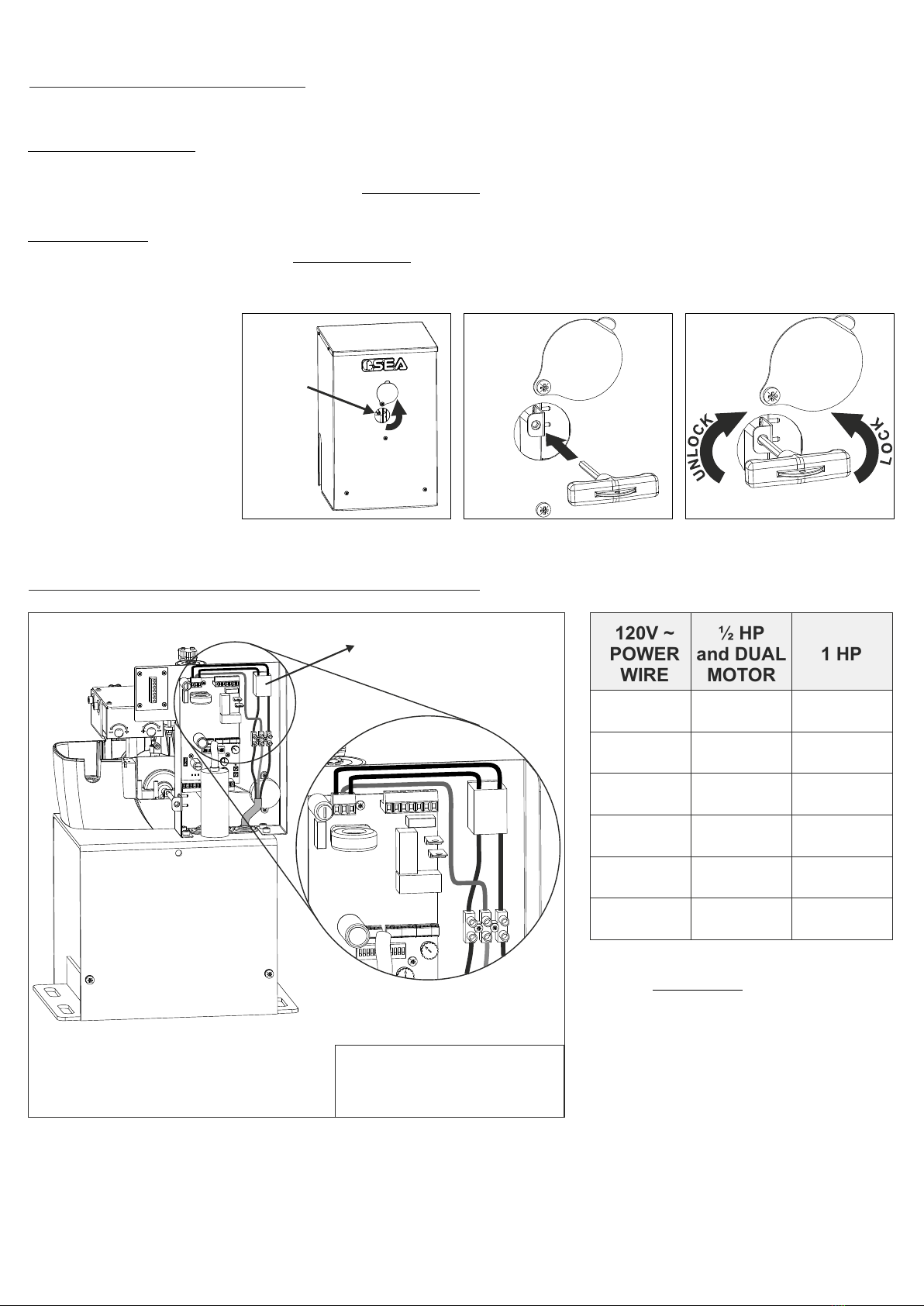
9. MANUAL RELEASE SYSTEM
To release the gate:
- Open the red door in front of the operator to left or right (Fig. 30).
- Insert the hexagon «T» key (Fig. 31) and without forcing turn the key clockwise until it stops (Fig. 32).
- Manually open and close the gate.
To reconnect:
- Insert the hexagon «T» key and without forcing turn anti-clockwise until it stops (Fig. 32).
- Slowly push the gate manually until the release is re-engaged.
Caution: do not attempt to use the operator electrically before reconnecting the drive.
WARNING: Always switch off the main power (120V) before servicing the operator
RELEASE
Fig. 30 Fig. 31 Fig. 32
Fig. 33
SEA recommend
to release the operator
only in case of power
failure.
Always contact a pro-
fessional installer in
case of malfunctioning
16 Gauge
14 Gauge
12 Gauge
10 Gauge
8 Gauge
4 Gauge
Up to
150 FT
250 FT
400 FT
650 FT
1000 FT
2200 FT
Up to
75 FT
125 FT
200 FT
325 FT
500 FT
1100 FT
P = Single Phase 120 V~
G = Ground
N = Neutral
10. SINGLE PHASE POWER CONNECTION (120 V~ )
120V ~
POWER
WIRE
½ HP
and DUAL
MOTOR
1 HP
ON - OFF
switch
Keep the power cables (motors,
power supply) SEPARATE from
the command cables (push
b u t t o n s , p h o t o c e l l s e t c ) .
In order to avoid any interference
use two separate cable sheaths
WARNING
13
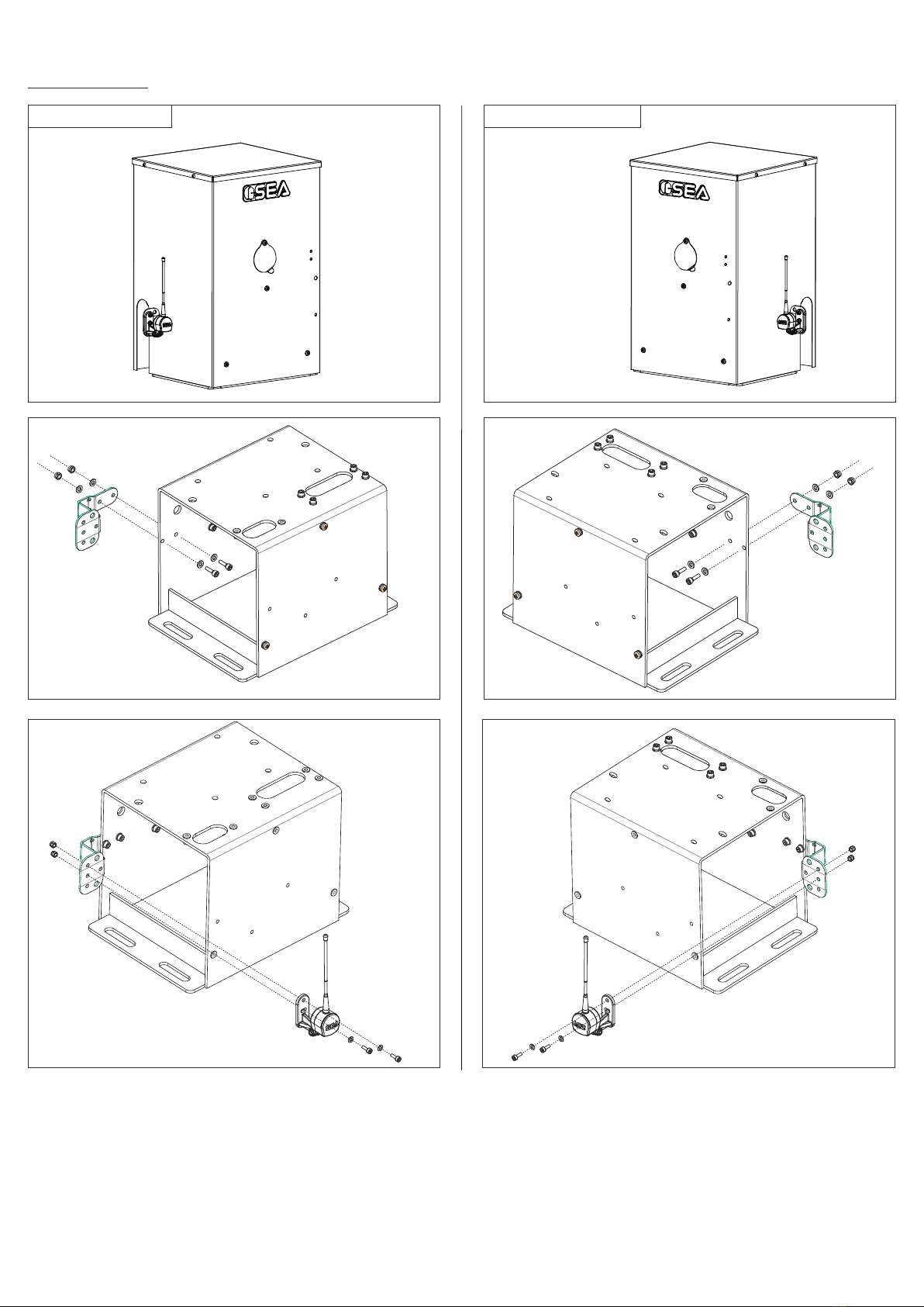
11. ANTENNA
LEFT MOUNTING RIGHT MOUNTING
Fig. 34 Fig. 37
Fig. 38
Fig. 39Fig. 36
Fig. 35
Note: The antenna must be connected on the clamps 1 and 2 of the control unit CN1 connector;
For further information on the antenna wiring diagram, please refer to the control unit user’s manual
14
Verify the battery back up systems by disconnecting the power source (120V)
REMEMBER to turn on the power source after check
Check the operating of all accessories, especially the functioning of all safety devices
and reversing sensors
PERIODICAL MAINTENANCE
Annual
Annual
Annual
Annual
Annual
Annual
Annual
Annual
Annual
Annual
Annual
Annual
Check the release functionality
Check the clutch functionality (if present)
Check the limit-switch conditions and functionality in opening and closing (if present)
Check the fixing screws
Check the connection cables integrity
Check the chain works perfectly and is well greased
Inspect the track for any signs of cracking or separation
Clean the gate track wheels and lubricate them with recommended lubricant
Check the tight of the hardware of the gate
Check for all corroded parts and replace them
All operations MUST be made exclusively by an authorized installer and when main power supply is OFF
After the periodical maintenance operations it is necessary to repeat the test of the automation and its commissioning
RISK EXAMINATION: The points pointed by arrows are potentially
dangerous. The installer must take a thorough risk examination to prevent
crushing, conveying, cutting, grappling, trapping so as to guarantee a safe
installation for people, things and animals (Re. Laws in force in the Country
where the installation has been made)
NOTICE: SEA USA Inc. can not be deemed responsible for any damage or
accident caused by product breaking, being damages or accidents due to a
failure to comply with the instructions herein. The guarantee will be void
and the manufacturer responsability will be nullified if SEA USA Inc. original
spare parts are not being used.
The electrical installation shall be carried out by a professional technician who will release documentation as requested by the laws
in force. Packaging materials such as plastic bags, foam polystyrene etc must be kept out of children’s reach as dangers may arise
WARNINGS The electrical installation and the operation logics must comply with current regulations. Keep the power cables
(motors, power supply) separated from the control cables (push-buttons, photocells, radio, etc.). Separate conduits should be used
to prevent noise issues. Note: Use “cable-glands” and/or “pipes/sheatings” close to the control panel box so to protect the
interconnection cables against pulling efforts
INTENDED USE The operator has been designed exclusively for the automation of sliding gates
SPARE PARTS: SEA USA Inc. - Doral 33172 - Miami (FL) - USA Telephone: ++1-305.594.1151 www.sea-usa.com
ENVIRONMENT SAFETY We recommend not to spoil the environment with product and circuit packing material
MAINTENANCE AND DECOMMISSION The decommission or stop or maintenance of the automation system must be carried out
by skilled and expert technicians.
GUARANTEE LIMITS For the guarantee see the sales conditions
NOTE: THE MANUFACTURER SHALL NOT SHOULDER ANY RESPONSIBILITIES IN CASE OF DAMAGE CAUSED BY
NAPPROPRIATE, WRONG OR CARELESS USE
SEA reserves the right to make all the necessary changes and modifications of the products or manuals without giving prior notice
TO THE ATTENTION OF THE END-USERS AND TECHNICIANS
GENERAL NOTICE
Tmin
-4°F
Tmax
+149°F
Humiditymin
5% without condensation
Humiditymax
90% without condensation
STORAGE TEMPERATURE
The product must be handled using suitable means

SALES CONDITIONS and WARRANTY
GENERAL WARNING: Installation must be realized using parts and accessories approved by SEA. SEA is not
responsible for incorrect installations and/or non-compliance with safety standards according to the law in-force.
SEA is in no way liable for any damages and/or malfunctioning due to using parts and accessories non-compliant
with the UL325 safety standards.
ORDERS: Orders are processed upon approval by SEA. Buyers must confirm orders by sending a written Purchase
Orders to SEA. Purchase Orders are intended as confirmation of orders and binding for the buyer, which accepts
SEA sales condition.
QUOTATION: Quotation and special offers with a non-specified duration expires automatically after 30 days.
PRICES: Prices are based on the Price List in force. Discounts and quotation from Sales Rep. and other selling
branches must be approved by SEA. Prices are F.O.B SEA Warehouse in Miami and do not include shipments costs.
SEA reserves the right to modify the price list at any time and provide notice to its sales network.
PAYMENT: Method of payments and terms are notified by SEA and displayed on the commercial invoice.
DELIVERY: The delivery time on the invoice is not binding and represents an estimated delivery. Shipments costs
will be charged to the buyer and SEA is not responsible for delays and/or damages occurred to the products during
shipment.
COMPLAINS: Complains and/or claims must be notified to SEA within 7 business days after receiving the products.
Claims and complains must be supported by original documents. Customer must contact the factory for instructions
and authorization. Merchandise returned for credit must be current, uninstalled and unused and returned in its
original packaging. Freight must be pre-paid on all authorized returns.
REPAIRS: Repairs and parts are subject to the availability in stock. Shipment of products for repairs must be pre-
paid by the customer. Products shipped without authorization, sender’s details and description of the problems will
be refused. Customers must contact SEA for instructions.
WARRANTY: for the original buyer only:
Hydraulic and oil-bath motors: 36 months warranty from the date of invoice on manufacturing, assembling and
workmanship defects.
Electro-mechanic motors and electronic control systems: 24 months warranty from the date of invoice on
manufacturing, assembling and workmanship defects.
Lepus and Full Tank Standard model: 60 months warranty from the date of invoice on manufacturing, assembling
and workmanship defects.
No warranty will be recognized for damages due to incorrect installation and/or improper use for which the product
was intended. SEA warranty obligations shall be limited to repair or replace the defective product/parts at SEA
option, upon examination of the products by SEA technical Staff. All replaced parts must remain property of SEA. The
warranty status of the product remains an unquestionable assessment of SEA. Buyer must ship pre-paid defective
products. Products under warranty will be returned pre-paid by SEA. Recognized defects, whatever their nature, will
not produce any responsibility and/or damage claims to SEA USA Inc and SEA s.r.l. Warranty shall not cover any
required labor activities. Warranty will in no case be recognized if alterations and any other changes will be found on
products. Warranty will not cover damages caused by carriers, expendable materials and faults due to improper use
with the products specifications. No indemnities are recognized during repairing and/or replacing of the products
under warranty. SEA USA Inc. and SEA s.r.l. decline any responsibility for damages to person and objects deriving
from non-compliance with safety standards, installation instructions or use of the products sold. It is intended that
warranty will be recognized only on products bought through the SEA authorized network. Products must be installed
by professionals. No warranty will be recognized if products are installed directly by the final user. Warranty does not
apply in case of unexpected events such as fire, flood, electrical power surge, lightning, vandalism and others.
SEA USA Inc. is not responsible for errors in technical information printed in catalogs and installation
manuals.

Table of contents
Other SEA Gate Opener manuals

SEA
SEA COMPACT 200 CP Instruction manual

SEA
SEA HALF TANK User manual

SEA
SEA TAURUS Instruction manual

SEA
SEA ALPHA 330 STANDARD Original instructions

SEA
SEA SATURN User manual

SEA
SEA LYRA User manual

SEA
SEA COUGAR 270 User manual

SEA
SEA LEPUS 800 Instruction manual

SEA
SEA SUPER FULL TANK 20 G6 380V User manual

SEA
SEA LEPUS Series User manual

SEA
SEA TORG Instruction manual

SEA
SEA ALPHA 200 STANDARD User manual

SEA
SEA Field Original instructions

SEA
SEA SCUTI User manual

SEA
SEA LIBRA Series Original instructions

SEA
SEA JOINT Original instructions

SEA
SEA ORION BOX 24V User manual

SEA
SEA SURF K 500 User manual

SEA
SEA Boxer 1000 User manual

SEA
SEA FIELD Series User manual


