SEA SURF K 500 User manual

2
IMPORTANT SAFETY INFORMATION
Clean and grease parts in movement (wheels, counter-connecting rod, release, etc.)
Check for corroded parts and replace if necessary
Check if the screws and all mounting hardwares are properly tighten
Check the conditions of wear and tear of the devices in movement
Check the correct drain of the rainwater
Check the integrity of the connection cables
Inspect the track for any signs of cracking or separation
Ensure that the gate moves freely
YEARLY
YEARLY
YEARLY
YEARLY
YEARLY
YEARLY
YEARLY
YEARLY
Check and confirm the proper operation of all safety devices (photocells, edge sensors etc)
Check and confirm the operation of all installed accessories
Check and confirm the operation of the manual release
Check the battery conditions and be sure that connections are free of corrosion
Verify the functionally of the battery backup, or power failure option
GENERAL SAFETY PRECAUTIONS
The following precautions are an integral and essential part of the product and must be supplied to the user;
Read them carefully as they contain important indications for the safe installation, use and maintenance.
1. These instruction must be kept and forwarded to all possible future users of the system.
2. This product must be used only for that which it has been expressly designed.
3. Any other use is to be considered improper and therefore dangerous.
4. The manufacturer cannot be held responsible for possible damage caused by improper or unreasonable use.
5. Avoid operating in the proximity of the hinges or moving mechanical parts.
6. Do not enter the path of the moving gate while in motion.
7. Do not obstruct the motion of the gate as this may cause a situation of danger.
8. Do not allow children to play or stay within the path of the moving gate.
9. Keep remote control or any other control devices out of the reach of children, in order to avoid possible involuntary
activation of the gate operator.
10. In case of break down or malfunctioning of the product, disconnect from the main power source. Do not attempt to
repair or intervene directly, contact only qualified personnel for repair.
11. Failure to comply with the above may create a situation of danger.
12. All cleaning, maintenance or repair work must be carried out by qualified personnel.
13. In order to guarantee that the system works efficiently and correctly it is important to have the manufacturer's
instructions on maintenance of the gate and operator carried out by qualified personnel.
14. In particular, regular checks are recommended in order to verify that the safety devices are operating correctly.
All installation, maintenance and repair work must be documented and made available to the user.
IMPORTANT SAFETY INSTRUCTIONS
WARNING – TO REDUCE THE RISK OF INJURY OR DEATH:
1. READ AND FOLLOW ALL INSTRUCTIONS.
2. Never let children operate or play with gate controls. Keep the remote control away from children.
3. Always keep people and objects away from the gate. NO ONE SHOULD CROSS THE PATH OF THE MOVING GATE.
4.Test the gate operator monthly. The gate MUST reverse on contact with a rigid object or stop when an object
activates the non-contact sensors. After adjusting the force or the limit of travel, retest the gate operator. Failure to
adjust and retest the gate operator properly can increase the risk of injury or death.
5. Use the emergency release only when the gate is not moving
6. KEEP GATES PROPERLY MAINTAINED. Read the owner’s manual. Have a qualified service person make repairs to
gate hardware.
7. The entrance is for vehicles only. PEDESTRIANS MUST USE SEPARATE ENTRANCE.
8. Every gate operator installation MUST have secondary protection devices agains entrapments, such as edge
sensors and photo beams more in particulary in places where the risk of entrapments is more likely to occur
9. SAVE THESE INSTRUCTIONS
PERIODIC MAINTENANCE
TURNING OFF THE POWER
BY MAIN SOURCE TURNED-OFF
TURNING ON THE POWER
!
YEARLY
YEARLY
YEARLY
YEARLY
YEARLY
ALL THE ABOVE DESCRIBED OPERATIONS MUST BE MADE EXCLUSIVELY BY AN AUTHORIZED INSTALLER

3
GENERAL SAFETY INFORMATION
An appliance shall be provided with an instruction manual.
The instruction manual shall give instructions for the installation, operation, and user maintenance of the appliance.
The installation instructions shall specify the need for a grounding-type receptacle for connection to the supply and
shall stress the importance of proper grounding.
The installation instructions shall inform the installer that permanent wiring is to be employed as required by local
codes, and instructions for conversion to permanent wiring shall be supplied.
INFORMATION SHALL BE SUPPLIED WITH A GATE OPERATOR FOR:
a. The required installation and adjustment of all devices and systems to effect the primary and secondary protection
against entrapment (where included with the operator).
b. The intended connections for all devices and systems to effect the primary and secondary protection against en-
trapment. The information shall be supplied in the instruction manual, wiring diagrams, separate instructions, or the
equivalent.
VEHICULAR GATE OPERATORS (OR SYSTEMS)
A vehicular gate operator shall be provided with the information in the instruction manual that defines the different
vehicular gate operator Class categories and give examples of each usage. The manual shall also indicate the use for
which the particular unit is intended as defined in Glossary, Section 3. The installation instructions for vehicular gate
operators shall include information on the Types of gate for which the gate operator is intended.
A gate operator shall be provided with the specific instructions describing all user adjustments required for proper
operation of the gate. Detailed instructions shall be provided regarding user adjustment of any clutch or pressure relief
adjustments provided. The instructions shall also indicate the need for periodic checking and adjustment by a qualified
technician of the control mechanism for force, speed, and sensitivity.
Instructions for the installation, adjustment, and wiring of external controls and devices serving as required protection
against entrapment shall be provided with the operator when such controls are shipped with the operator.
Instructions regarding intended installation of the gate operator shall be supplied as part of the installation instructions
or as a separate document. The following instructions or the equivalent shall be supplied where applicable:
IMPORTANT INSTALLATION INSTRUCTIONS
1. Install the gate operator only when:
a. The operator is appropriate for the construction of the gate and the usage Class of the gate
b. All openings of a horizontal slide gate are guarded or screened from the bottom of the gate to a minimum of 4 feet
(1.22 m) above the ground to prevent a 2-1/4 inch (57.2 mm) diameter sphere from passing through the openings
anywhere in the gate, and in that portion of the adjacent fence that the gate covers in the open position
c. All exposed pinch points are eliminated or guarded
d. Guarding is supplied for exposed rollers
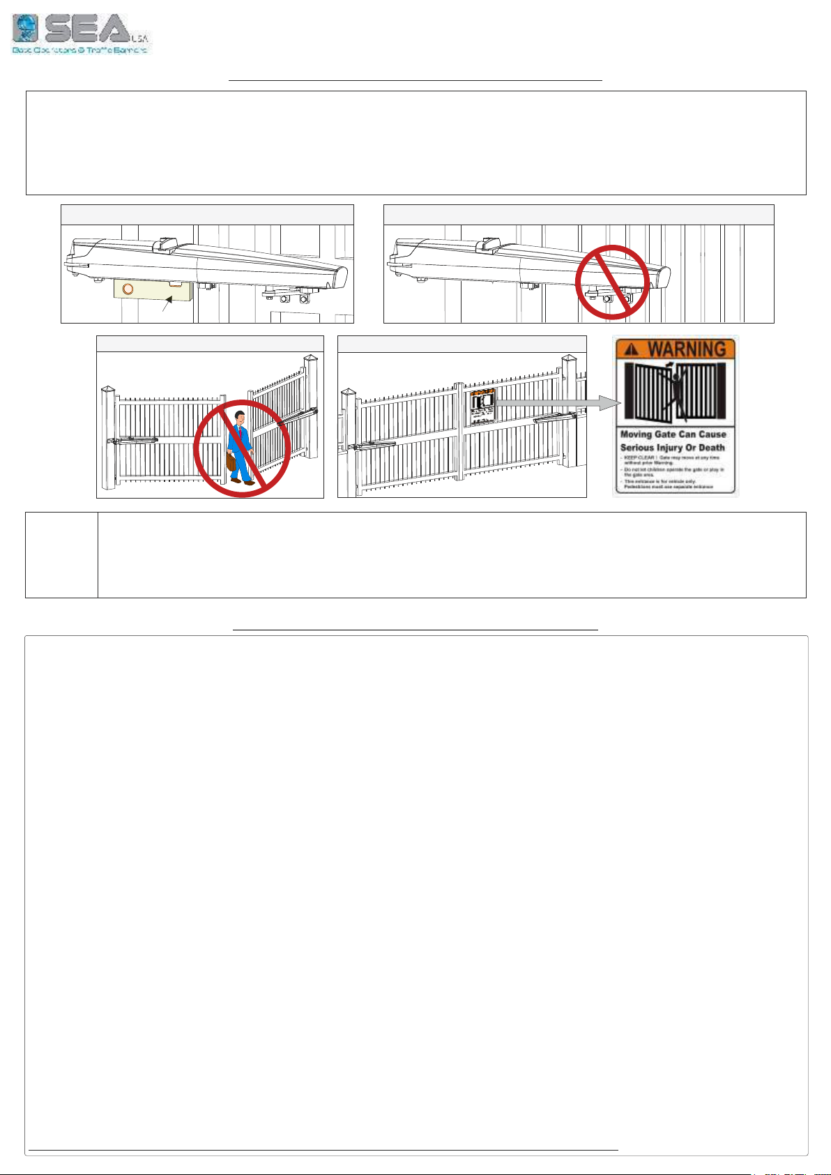
2. The operator is intended for installation only on gates used for vehicles. Pedestrians must be supplied with a
separate access opening. The partial access opening shall be designed to promote pedestrian usage. Locate the gate
such that persons will not come in contact with the vehicular gate during the entire path of travel of the vehicular gate.
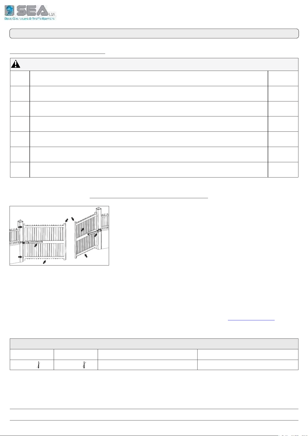
3. The gate must be installed in a location so that enough clearance is supplied between the gate and adjacent
structures when opening and closing to reduce the risk of entrapment. Swinging gates shall not open into public access
areas.
4. The gate must be properly installed and work freely in both directions prior to the installation of the gate operator. Do
not over-tighten the operator clutch or pressure relief valve to compensate for a damaged gate.
5. The gate operator controls must be placed so that the user has full view of the gate area when the gate is moving and
AWAY FROM THE GATE PATH PERIMETER.
6. Controls intended for user activation must be located at least six feet (6’) away from any moving part of the gate and
where the user is prevented from reaching over, under, around or through the gate to operate the controls. Outdoor or
easily accessible controls shall have a security feature to prevent unauthorized use.
7. The Stop and/or Reset button must be located in the line-of-sight of the gate. Activation of the reset control shall not
cause the operator to start.
8. A minimum of two (2) WARNING SIGNS shall be installed, one on each side of the gate where easily visible
9. FOR GATE OPERATORS UTILIZING A NON-CONTACT SENSOR:
a. See instructions on the placement of non-contact sensors for each Type of application
b. Care shall be exercised to reduce the risk of nuisance tripping, such as when a vehicle, trips the sensor while the
gate is still moving
c. One or more non-contact sensors shall be located where the risk of entrapment or obstruction exists, such as the
perimeter reachable by a moving gate or barrier

4
10. FOR A GATE OPERATOR UTILIZING A CONTACT SENSOR:
a. One or more contact sensors shall be located where the risk of entrapment or obstruction exists, such as at the
leading edge, trailing edge, and postmounted both inside and outside of a vehicular horizontal slide gate.
b. One or more contact sensors shall be located at the bottom edge of a vehicular vertical lift gate.
c. One or more contact sensors shall be located at the pinch point of a vehicular vertical pivot gate.
d. A hardwired contact sensor shall be located and its wiring arranged so that the communication between the sensor
and the gate operator is not subjected to mechanical damage.
e. A wireless contact sensor such as one that transmits radio frequency (RF) signals to the gate operator for
entrapment protection functions shall be located where the transmission of the signals are not obstructed or
impeded by building structures, natural landscaping or similar obstruction. A wireless contact sensor shall
function under the intended end-use conditions.
f. One or more contact sensors shall be located on the inside and outside leading edge of a swing gate. Additionally, if
the bottom edge of a swing gate is greater than 6 inches (152 mm) above the ground at any point in its arc of travel,
one or more contact sensors shall be located on the bottom edge.
g. One or more contact sensors shall be located at the bottom edge of a vertical barrier (arm).
INSTRUCTION REGARDING INTENDED OPERATION OF THE GATE OPERATOR SHALL BE PROVIDED AS PART OF THE USER
INSTRUCTIONS OR AS A SEPARATE DOCUMENT. THE FOLLOWING INSTRUCTIONS OR THE EQUIVALENT SHALL BE PROVIDED
NOTICE
As for misunderstandings that may arise refer to your area distributor or call our help desk. These instructions are part
of the device and must be kept in a well known place. The installer shall follow the provided instructions thoroughly.
SEA products must only be used to automate doors, gates and wings. Any initiative taken without SEA USA Inc. explicit
authorization will preserve the manufacturer from whatsoever responsibility. The installer shall provide warning notices
on not assessable further risks. SEA USA Inc. in its relentless aim to improve the products, is allowed to make
whatsoever adjustment without giving notice. This doesn’t oblige SEA to up-grade the past production. SEA USA Inc.
can not be deemed responsible for any damage or accident caused by product breaking, being damages or accidents
due to a failure to comply with the instructions herein. The guarantee will be void and the manufacturer responsibility
will be nullified if SEA USA Inc. original spare parts are not being used. The electrical installation shall be carried out by
a professional technician who will release documentation as requested by the laws in force. Packaging materials such
as plastic bags, foam polystyrene, nails etc must be kept out of children’s reach as dangers may arise.
TO RESPECT THE LAWS IN FORCE IT IS RECOMMENDED TO USE THE ENCODER WITH THE ELECTRONIC CONTROL UNIT
UL 325 ED. 6th ENTRAPMENT PROTECTION REQUIREMENTS
VEHICULAR GATE OPERATOR CLASSES
Residential Vehicular Gate Operator-Class I: A vehicular gate operator (or system) intended for use in garages or
parking areas associated with a residence of one-to-four single families
Commercial/General Access Vehicular Gate Operator-Class II: A vehicular gate operator (or system) intended for
use in a commercial location or building such as a multi-family housing unit (five or more single family units), hotel,
garages, retail store, or other buildings accessible by or servicing the general public
Industrial/Limited Access Vehicular Gate Operator–Class III: A vehicular gate operator (or system) intended for
use in an industrial location or building such as a factory or loading dock area or other locations not accessible by or
intended to service the general public
Restricted Access Vehicular Gate Operator–Class IV: A vehicular gate operator (or system) intended for use in an
industrial location or building such as a factory or loading dock area or other locations not accessible by or intended to
service the general public
THIS VEHICULAR GATE OPERATOR MUST BE INSTALLED WITH AT LEAST TWO INDEPENDENT ENTRAPMENT PROTECTION MEANS
AS SPECIFIED IN THE TABLE BELOW
HORIZONTAL SLIDE
VERTICAL LIFT - VERTICAL PIVOT
ENTRAPMENT
PROTECTION
TYPES
TYPE A
TYPE B1
TYPE B2
TYPE C
Inherent entrapment protection system
Non-contact sensors such as photoelectric sensors or equivalents
Contact sensors such as edge sensors or equivalent devices
Inherent force limiting, inherent adjustable clutch or inherent pressure relief device
TYPE D Actuating device requiring constant pressure to maintain opening or closing motion of the gate
SWING
VERTICAL BARRIER (ARM)
A , B1*, B2* or D A , B1*, B2*, C or D
GATE OPERATOR CATEGORY (Effective January, 12 2016)

5
NOTES:
1. The same type of device shall not be used for both entrapment protection means. Use of a single device to cover both
the opening and closing directions is in accordance with the requirement; however, a single device is not required to
cover both directions. Tice installer is required to install entrapment protection devices in each entrapment zone
2. FOR VERITICAL BARRIERS ONLY: Barrier gate operators (arm) that is not intended to move toward a rigid objact
closer than 16 inches (406 mm) are not required to be provided with a means of entrapment protection
* B1 and B2 means of entrapment protection MUST be MONITORED
Changes to UL 325 ED. 6th for Gate Operators
Starting on Jan. 12, 2016, new UL 325 changes take effect, bringing a series of new mandates for the gate
operator industry. Here’s a quick guide to the key modifications
1. ENTRAPMENT-PROTECTION DEVICES: Gate operators are required to have a minimum of two independent means of
entrapment protection where the risk of entrapment or obstruction exists. A manufacturer can use two inherent-type
systems, two external-type systems, or an inherent and an external system to meet the requirement. However, the
same type of device cannot be used for both means of protection.
2. MONITORING REQUIRED: An external non-contact sensor or contact sensor may be used as a means of entrapment
protection. However, the sensor must be monitored once every cycle for:
a. the correct connection to the operator
b. the correct operation of the sensor
If the device is not present, not functioning, or is shorted, then the gate operator can only be operated by constant
pressure on the control device. Portable wireless controls will not function in this case.
3. ENTRAPMENT RISK IDENTIFICATION: As in the past, it’s up to the installer to examine the installation and determine
where a risk of entrapment or obstruction exists. Manufacturers are required to provide instructions for the placement
of external devices, but they give only examples of suggested entrapment protection in their installation manuals. If the
installer identifies a risk of entrapment or obstruction, at least two independent means of entrapment protection are
required.
4.TERMINOLOGY CHANGE: The terms «primary» and «secondary» have been removed in the description of entrapment
protection devices. This was done to emphasize that all entrapment protection devices are equally important.
5. THE END OF TYPE E: Type E (audible alarm) devices can no longer be used for entrapment protection. This change
was made because the Type E device is really a warning device, not an entrapment-protection device. Also, all gate
operator classes are now required to have an audio alarm that sounds when two successive obstructions are
encountered via a contact-type system.
6. ACCESS CONTROL LOCATION FOR EMERGENCY USE: An exception has been added in the manufacturer’s instructional
requirements for the location of controls that operate the gate.
The instructional requirements state that these controls must be at least 6' away from any moving part of the gate. In the
new exception, «Emergency access controls only accessible by authorized personnel (e.g., fire, police, EMS) may be
placed at any location in the line-of-sight of the gate».
7. BARRIER-ARM OPERATOR EXCEPTION: An exception has changed for barrier-arm gate operators requiring entrapment
protection. The previous exception stated that a barrier-arm operator did not require entrapment protection if the arm
did not move toward a rigid object closer than 2". The distance has been reduced to 16" so it more closely aligns with the
industry-defined entrapment protection provisions in ASTM F2200.
8. GATE OPERATOR CLASS II AND CLASS III DEFINITIONS: The definitions for installation classes for gate operators were
modified. Class II now includes commercial locations accessible to the general public. Class III was refined to specify
industrial locations not accessible to the general public. These changes, while seemingly minor, may affect which gate
operator is suitable for a particular installation location.

6
The first thing to check is that the gate is in good running order:
A - The gate is rigid and straight and runs smoothly throughout its travel
B - The length of each leaf must comply with max. length indicated on technical specifications of the model
C - The weight of each leaf must comply with max. weight indicated on technical specifications of the model
D - The hinges are hardly anchored and are able to support the torque of the operator; they do not have irregular
movements and/or any friction during the whole movement of the leaf.
- SEA operators have been designed for the automation of gates for vehicles use only
Be aware to avoid the crossing of the gate path because it is very dangerous for pedestrians
- Install the warning signs on each side of the gate and in avisible zone to inform the pedestrians
about the danger they run when passing or resting in the environment of the gate
- For more safety SEA advises to install infrared photocells
GATE WARNINGS AND PRECAUTIONS
Level
SALES CONDITIONS and WARRANTY
GENERAL WARNING: Installation must be realized using parts and accessories approved by SEA. SEA is not responsible for incorrect
installations and/or non-compliance with safety standards according to the law in-force. SEA is in no way liable for any damages and/or
malfunctioning due to using parts and accessories non-compliant with the UL325 safety standards.
ORDERS: Orders are processed upon approval by SEA. Buyers must confirm orders by sending a written Purchase Orders to SEA. Purchase
Orders are intended as confirmation of orders and binding for the buyer, which accepts SEA sales condition.
QUOTATION: Quotation and special offers with a non-specified duration expires automatically after 30 days.
PRICES: Prices are based on the Price List in force. Discounts and quotation from Sales Rep. and other selling branches must be approved by
SEA. Prices are F.O.B SEA Warehouse in Miami and do not include shipments costs. SEA reserves the right to modify the price list at any time
and provide notice to its sales network.
PAYMENT: Method of payments and terms are notified by SEA and displayed on the commercial invoice.
DELIVERY: The delivery time on the invoice is not binding and represents an estimated delivery. Shipments costs will be charged to the buyer
and SEA is not responsible for delays and/or damages occurred to the products during shipment.
COMPLAINS: Complains and/or claims must be notified to SEA within 7 business days after receiving the products. Claims and complains must
be supported by original documents. Customer must contact the factory for instructions and authorization. Merchandise returned for credit must
be current, uninstalled and unused and returned in its original packaging. Freight must be pre-paid on all authorized returns.
REPAIRS: Repairs and parts are subject to the availability in stock. Shipment of products for repairs must be pre-paid by the customer. Products
shipped without authorization, sender’s details and description of the problems will be refused. Customers must contact SEA for instructions.
WARRANTY: for the original buyer only: Hydraulic and oil-bath motors: 36 months warranty from the date of invoice on manufacturing,
assembling and workmanship defects. Electro-mechanic motors and electronic control systems: 24 months warranty from the date of invoice on
manufacturing, assembling and workmanship defects. Lepus and Full Tank Standard model: 60 months warranty from the date of invoice on
manufacturing, assembling and workmanship defects. No warranty will be recognized for damages due to incorrect installation and/or improper
use for which the product was intended. SEA warranty obligations shall be limited to repair or replace the defective product/parts at SEA option,
upon examination of the products by SEA technical Staff. All replaced parts must remain property of SEA. The warranty status of the product
remains an unquestionable assessment of SEA. Buyer must ship pre-paid defective products. Products under warranty will be returned pre-paid
by SEA. Recognized defects, whatever their nature, will not produce any responsibility and/or damage claims to SEA USA Inc and SEA .
Warranty shall not cover any required labor activities. Warranty will in no case be recognized if alterations and any other changes will be found on
products. Warranty will not cover damages caused by carriers, expendable materials and faults due to improper use with the products
specifications. No indemnities are recognized during repairing and/or replacing of the products under warranty. SEA USA Inc. and SEA decline
any responsibility for damages to person and objects deriving from non-compliance with safety standards, installation instructions or use of the
products sold. It is intended that warranty will be recognized only on products bought through the SEA authorized network. Products must be
installed by professionals. No warranty will be recognized if products are installed directly by the final user. Warranty does not apply in case of
unexpected events such as fire, flood, electrical power surge, lightning, vandalism and others.
SEA USA Inc. is not responsible for errors in technical information printed in catalogs and installation manuals.
INSTALL THE OPERATOR IN THE CORRECT POSITION DO NOT INSTALL THE FRONT BRACKET IN A WEAK PART OF THE GATE
NOT FOR PEDESTRIAN OPENING! INSTALL THE WARNING SIGNS!

7
1
2
4
36
5
7
8
10
11
9
12
1. Aluminium casing
2. Front fixing bracket
3. Back fixing bracket
4. Release system
5. Capacitor
6. Motor
8
7. Gear reducer
8. Bearings
9. Stop in opening
10. Stop in closing
11. Endless-screw
12. Lead screw barrel nut
Fig. 1
* with mechanical stop in
opening and closing inserted
SURF (350 - 450) , is an irreversible electromechanical swing gate operator strong and safe, easy to install,
for leaf length up to is equipped with release system through key, which allows the 14,76 feet. SURF operator
manual release of the leaf in case of emergency or black out
TECHNICAL SPECIFICATIONS
3,86
15,6 15,75*
31,3
4,13
34,56
DIMENSIONS (inches)
Fig. 4
Fig. 2
6. Motor
7. Metallic bever gear
8. Bearings
9. Endless-screw
10. Lead screw barrel nut
1. Aluminium casing
2. Front fixing bracket
3. Back fixing bracket
4. Release system
5. Capacitor
SURF K is an irreversible electromechanical swing gate operator, strong and safe, easy to install, for leaf
length up to 16,40 feet. SURF K operator is equipped with release system with key, which allows the manual
release of the leaf in case of emergency or black out
1
2
3
4
5
7
8
9
10
6
8
Fig. 3
39,50
36,61
3,10
SURF SURF K

8
TECHNICAL DATA
15,75 inches
50
40
- 4° F + 131° F
-
2000 N
-
17,64 Lb
17,20 Lb
IP 44
12 ft 15 ft
16 ft
900 Lb 1100 Lb1100 Lb
24Vcc
60 W
2,5 A
2350 rpm
Adjustable
TECHNICAL DATA
Power supply
Max. power
Max. absorbed current
Motor speed
Shaft stroke
Shaft speed
Cycle/hour
(operating at 20°C)
Operating temperature
Max. thrust
Capacitor
Operator weight
Protection
Max. leaf length
Max. leaf weight
Motor thermal protection
SURF 350 24V SURF 450 24V
SURF 450 24V FAST
SURF K 500 H 24V
50
3,5 A
120 W
3300 rpm
60
9 ft
700 Lb
TECHNICAL DATA
Power supply
Max. power
Max. absorbed current
Motor speed
Shaft stroke
Shaft speed
Cycle/hour
(operating at 20°C)
Operating temperature
Max. thrust
Capacitor
Operator weight
Protection
Max. leaf length
Max. leaf weight
Motor thermal protection
SURF 350 120V SURF 450 H BR 36V SURF K 500 H BR 36V
120V (± 5%) 50/60 Hz ~
280 W
3 A
1430 rpm
36Vcc
260 W
-
Adjustable
Adjustable
45
15,75 inches 15,75'' (14,57'' using magnetic
limit switch)
1000 Lb
13 ft
IP 44
1100 Lb
16 ft
15 ft
16,53 Lb 17,20 Lb
17,64 Lb
60 µF (not on board)
0,71 inches/sec.
20
- 4° F + 131° F
266° F
3000 N
-
*
*
*
The frequency of use is only valid for the first operating hour and at a temperature of 68° F
*
The frequency of use is only valid for the first operating hour and at a temperature of 68° F
2000 N
1 A
2300 rpm
50
15,75''
( using
magnetic limit switch)
14,57''

9
MAIN PARTS
Motor
electric
cable
Front fixing bracket
Manual release
Covering lid for terminal board
Hooking
pin
USING GRAPHICS
16 feet
12 feet
15 feet
40
Fig. 5
20
50
SURF 350 (24V)
SURF 350 (24V)
SURF 350 (120V)
SURF
350
(120V)
SURF 450 (24V)
SURF 450 (24V)
MAX LEAF LENGTH
CYCLES/HOUR
13 feet
SURF K 500 H (24V)
SURF K 500 H (24V)
Fig. 6
45
SURF 450 BR (36V)
SURF K 500 H BR (36V)
SURF 450 BR (36V)
SURF K BR (36V)
Covering lid for terminal board
Rear
fixing
bracket
Rear
fixing
bracket
Front
fixing
bracket
Manual release
Hooking
pin
SURF
SURF K
Fig. 7
Fig. 8
9 feet
SURF 450 FAST (24V)
60
OPERATOR
SURF 450
FAST (24V)
Limit-switch
electric cable
Motor
electric
cable
Weight
16
Leaf length
900 Lb
15
912
1100 Lb
400 Lb
5 feet
SURF 350 (24V)
13
1000 Lb
SURF 350 (120V)
SURF K 500 H (24V)
SURF K 500 H BR (36V)
SURF 450 FAST (24V)
700 Lb
Weight
Leaf length
900 Lb
15
912
1100 Lb
400 Lb
5 feet 13
1000 Lb
SURF 450 (24V) - SURF 450 H BR (36V)
700 Lb

10
STANDARD INSTALLATION
Fig. 9
* For 24V operators (SURF or SURF K) use 2 x 2,5 cables type to connect them to the control unit
11
2
2
3
4
5
6
7
8
9
10
10
11
2x1
4x1
4x1,5 *
2x1
4x2,5
4x1
1xRG58
4x1
4x1,5 *
Fig. 10
2x1,5
EXIT
ENTRY
1) Operator
2) Mechanical stop
3) Electronic control unit
4) Flashing lamp
5) Right Photocell (Dx)
6) Differential switch 16A - 0,03A
7) Left Photocell (Sx)
8) Start/Stop push button with key
9) Antenna
10) Support for photocells
11) Warning notice
Mechanical
stop
in closing
Mechanical
stop
in opening
GATE ARRANGEMENT
Some checks on the gate are required to verify the
operator fitting; Make sure that:
A. the fix and the moving parts of the gate are
strong and non-deformable;
B. the length of each leaf does not exceed the
length propped-up by the operator type (see Fig. 6)
C. the weight of each leaf does not exceed the
weight propped-up by the operator type (see Fig. 6)
D. the hinges and the general structure must be in
good conditions and able to support the operator
thrust; the gate must move smoothly throughout its
whole travel;
Where possible, it is advisable to install
mechanical stops on the ground for the better
functioning of the operator

11
INWARD INSTALLATION OUTWARD INSTALLATION
inside
inside
inside
outside
outside
outside
SURF INSTALLATION TYPE
Fig. 11 Fig. 12
Fig. 13
a
(inches)
b
(inches)
d
max
(inches)
Max
opening
angle
Max
opening
angle
Max
stroke
(inches)
Max
stroke
(inches)
Stroke
per 90°
(inches)
e
(inches)
b
c
d
a
e
105°
105°
105°
100°
100°
100°
95°
95°
95°
90°
90°
90°
90°
90°
90°
90°
90°
90°
f *
(inches)
5,12
5,12
5,12
5,12
5,12
5,12
5,12
5,12
5,12
5,12
5,12
5,12
5,12
5,12
5,12
5,12
5,12
5,12
f
ac
d
e
90°
95°
100°
100°
100°
100°
100°
100°
100°
f
b
Fig. 14
outside
inside
IN ANY CASE,
I N S TA L L T H E
O P E R A T O R
ALWAYS INSIDE
THE PROPERTY
INWARD INSTALLATION
OUTWARD INSTALLATION
* The « f » dimension has been
calculated on a 1,57 inches thick gate
Total stroke 15,75 in - max. recommended stroke 14,96 in
8,26
7,87
7,48
8,66
8,26
7,87
9,05
8,66
8,26
9,44
9,05
8,66
9,84
9,44
9,05
10,23
9,84
9,44
6,30
6,30
6,30
5,90
5,90
5,90
5,51
5,51
5,51
5,11
5,11
5,11
4,72
4,72
4,72
4,33
4,33
4,33
5,90
5,51
5,11
6,30
5,90
5,51
6,70
6,30
5,90
7,08
6,70
6,30
7,48
7,08
6,70
7,87
7,48
7,08
24,80
24,80
24,80
25,19
25,19
25,19
25,59
25,59
25,59
25,98
25,98
25,98
26,37
26,37
26,37
26,77
26,77
26,77
14,96
15,35
15,74
14,56
14,96
15,35
14,37
14,76
15,15
14,17
14,56
14,96
14,17
14,56
14,96
14,17
14,56
14,96
13,97
14,37
14,76
13,97
14,37
14,76
13,97
14,37
14,76
14,17
14,56
14,96
14,17
14,56
14,96
14,17
14,56
14,96
* The « f » dimension has been
calculated on a 1,57 inches thick gate
Total stroke 15,75 in - max. recommended stroke 14,96 in
a
(inches)
b
(inches)
Stroke
per 90°
(inches)
e
(inches)
f *
(inches)
10,82
11,41
11,61
11,81
11,81
11,81
11,81
12,00
12,00
10,82
10,82
11,02
11,02
11,02
11,02
11,02
11,02
11,02
20,86
21,25
21,65
22,04
22,44
22,83
23,22
23,62
24,01
3,14
3,56
3,93
4,33
4,72
5,11
5,51
5,90
6,30
7,87
7,48
7,08
6,70
6,30
5,90
5,51
5,11
4,72
5,12
5,12
5,12
5,12
5,12
5,12
5,12
5,12
5,12

12
Fig. 15 Fig. 16
Fig. 17
Fig. 18
IN ANY CASE,
I N S TA L L T H E
O P E R A T O R
ALWAYS INSIDE
THE PROPERTY
b
c
d
a
e
f
9,45
9,84
10,24
8,27
8,66
9,05
9,45
9,05
8,66
8,66
8,27
7,87
6,30
6,30
5,90
5,51
4,72
4,72
4,72
3,93
3,93
3,93
5,51
5,51
5,51
6,30
6,30
6,30
6,30
7,10
7,90
8,27
c
(inches)
2,48
2,48
2,48
2,48
2,48
2,48
2,48
2,48
2,48
2,48
2,48
2,48
2,48
2,48
2,48
2,48
6,97
7,36
7,76
5,79
6,18
6,57
6,97
6,57
6,18
6,18
5,79
5,39
3,82
3,82
3,42
3,03
5,51
5,51
5,51
5,51
5,51
5,51
5,51
5,51
5,51
5,51
5,51
5,51
5,51
5,51
5,51
5,51
14,17
14,57
14,96
12,20
12,60
12,99
14,96
14,57
14,17
14,96
14,57
14,17
12,60
13,39
13,78
13,78
Stroke
for 90°
Opening
for 90°
Max Stroke
for opening
angle (inches)
Max
opening
angle
3,54
3,54
3,54
3,54
3,54
3,54
3,54
3,54
3,54
3,54
3,54
3,54
3,54
3,54
3,54
3,54
15,00
15,35
15,51
12,56
12,95
13,35
15,51
15,43
15,32
15,55
15,55
15,55
14,61
15,43
15,75
15,55
100°
100°
95°
95°
95°
95°
95°
100°
105°
95°
100°
105°
115°
110°
105°
105°
47,64
47,64
47,64
48,54
48,54
48,54
46,97
46,97
46,97
46,22
46,22
46,22
46,26
45,47
44,76
44,29
5,90
5,90
5,90
6,30
6,30
6,30
6,30
7,10
7,90
3,93
4,72
5,51
4,72
5,51
6,30
7,10
5,51
6,30
2,48
2,48
2,48
2,48
2,48
2,48
2,48
2,48
2,48
3,43
3,43
3,43
3,82
3,82
3,82
3,82
4,61
5,39
5,51
5,51
5,51
5,51
5,51
5,51
5,51
5,51
5,51
9,84
10,63
11,42
11,02
11,81
12,60
13,39
12,60
14,17
3,54
3,54
3,54
3,54
3,54
3,54
3,54
3,54
3,54
10,20
11,69
12,99
12,09
13,03
14,37
15,43
13,82
15,51
95°
105°
110°
105°
105°
110°
110°
105°
105°
41,14
41,93
42,72
41,93
42,72
43,50
44,29
42,72
43,46
a
b
c
d
e
f
outside
inside
outside
inside
outside
outside
inside
inside
* The « f » dimension has been cal-
culated on a 1,57 inches thick gate
SURF K INSTALLATION TYPE
INWARD INSTALLATION
OUTWARD INSTALLATION
* The « f » dimension has been cal-
culated on a 1,57 inches thick gate
a
(inches) b
(inches)
d
max
(inches)
e
(inches)
f *
(inches) (inches)
Total stroke 15,75 in - max. recommended stroke 14,96 in
(inches)
Max
opening
angle
c
(inches)
Stroke
for 90°
Opening
for 90°
Max Stroke
for opening
angle (inches)
a
(inches)
b
(inches)
d
max
(inches)
e
(inches)
f *
(inches) (inches) (inches)
INWARD INSTALLATION OUTWARD INSTALLATION

13
Fig. 19
ad
b
42,05
2,36
6,10 Minimum
d
7,87
3,14 Minimum
INSTALLATION ON MASONRY PILLARS BY MAKING A RECESS
2,36
6,10 Minimum
Fig. 20
ad
b
d
42,05
2,36
6,10 Minimum
7,87
3,14 Minimum
2,36
6,10 Minimum
During installation, make
sure that the connection
cables do not interfere
with the recess
During installation, make
sure that the connection
cables do not interfere
with the recess
CAUTION!
CAUTION!
NOTES
NOTES
1 - dimensions in inches
2 - In case you need to
make a recess, observe
the shown dimensions
1 - dimensions in inches
2 - In case you need to
make a recess, observe
the shown dimensions
SURF
SURF K

14
If the rear fixing bracket has to be screwed using the
holes marked as «A», so the fixing bracket must be cut at
a distance of 2,56 inches from its end (Fig. 23).
It is not necessary to cut the bracket if using other holes
The support must be positioned so that the
operator is in a perfect horizontal position (Fig. 21 - 22)
A
A
AA
A
2,56'’
Fig. 23
Fig. 24
(1)
Nut (1)
CAUTION! To avoid the oscillation of the
operator during the operating phase, it is recom-
mended to adjust the nut (1) (Fig. 24) taking care
to not block the rotation of the operator on the
fixing bracket
Fig. 25
1 - For the correct operation it is very important to position both the operator and its front
and rear fixing brackets, in a perfectly horizontal way, by using a level, as shown in Fig. 21 - 22
2 - Before mounting operator on the rear and the front brackets, lubricate with water repellent grease
3 - The operator must be mounted with the release facing upwards (Fig. 21 - 22)
Level
Fig. 22
PRELIMINARY NOTES
Release
REAR FIXING BRACKET MOUNTING
REAR FIXING BRACKET TO BE SCREWED
WARNING!
once the rear bracket has been fixed, immediately
fix the front bracket, always keeping the operator in a
horizontal position. Do not leave the front of the operator
detached because it would fall down causing damage
Level
Fig. 21
Release
SURF
SURF K

15
SCREWED FRONT FIXING BRACKET
Fig. 28
1 - According to the gate type (wood, iron, aluminium) the front bracket can be welded or screwed
2 - Before mounting the rear and the front fixing brackets, lubricate with water repellent grease
3 - The operator position must be perfectly horizontal (use a level as shown in Fig. 28 or 29)
4 - Make sure that the front fixing bracket DOES NOT TILT when it reaches the stop (Fig. 36) or
malfunctions on the electronic limit switches may occur
Level
Front Fixing
Bracket
(A)
(A)
Fig. 29
PRELIMINARY NOTES
FRONT FIXING BRACKET MOUNTING
Once the operator has been mounted on the rear fixing bracket,
close the leaf and proceed as follows:
1) Release the operator keeping it always in a horizontal position
2) Screw the front fixing bracket onto the gate in correspondence of
the holes made respecting the dimensions as per Fig. 26 - 27
3) SURF: Place the operator pin on the bracket (previously
lubricated) (Fig. 29)
SURF K: Insert the bracket into the housing pin on the operator
extremity (previously lubricated) (Fig. 31)
4) Tighten the «A» screw to max 8.5 Nm
CAUTION: Lubricate the bracket and the pin with grease
before installing the front fixing bracket
Fig. 26
Fig. 27
4,33'’
2,44'’
1,50'’
2,44'’
= =
1,50'’
SURF
Hooking
pin
Hooking
pin
Fig. 30
Level
Fig. 31
SURF K
WELDED FRONT FIXING BRACKET
4,33'’
Fig. 32
Once the operator has been mounted on the rear fixing
bracket, close the leaf and proceed as follows:
1) Release the operator keeping it always horizontal
2) Weld the front fixing bracket on the gate operating on
the points indicated by the arrows (Fig. 32)
3) SURF: Place the operator pin on the bracket
(previously lubricated) (Fig. 29)
SURF K: Insert the bracket into the housing pin on the
operator extremity (previously lubricated) (Fig. 31)
4) Tighten the «A» screw to max 8.5 Nm

16
When positioning the front fixing bracket on the gate, always consider
the offset in respect to the central axis of the operator (see Fig. 33)
2,40'’
0,91'’
Fig. 33
Max = 2,55 in
INSTALLATION OF MECHANICAL STOP FOR SURF
Max = 2,95 in
MECHANICAL STOP IN CLOSING
MECHANICAL STOP IN OPENING
Fig. 34
Fig. 35
Make sure that the front fixing bracket DOES NOT TILT when it reaches
the stop (Fig. 36) or malfunctions on the electronic limit switches may occur
Front fixing bracket
(shown in opening and closing position)
Fig. 36

17
LIMIT SWITCH
IN CLOSING
1,18 inches
Max
MAGNETIC LIMIT SWITCHES for SURF K
LIMIT SWITCH
IN OPENING
2,17 inches
Max
INTERNAL RELEASE SYSTEM
To release the operator proceed as
follows:
1) Turn counter-clockwise the lock
protection cover (Fig. 38)
2) Insert the key and turn of about 90°
clockwise (Fig. 39)
3) handleTurn the counter-clockwise to
release the operator (Fig. 40)
To lock the operator proceed as follows:
1) Turn the handle clockwise to revert it to
the initial position
2) Turn the key about 90° counter-
clockwise (Fig. 41)
3) After having relocked the operator, close
the lock protection cover to prevent
damages due to atmospheric agents
NOTE: for a proper operation of the
manual release it is recommended to
observe the current regulations
regarding the thrust force
Handle
Handle
Lock
protection
cover
90°
Fig. 41
Fig. 38
Fig. 37
90°
Fig. 39
Fig. 40
LOCK
RELEASE

18
12
- Make connections only after installation is complete and when the power supply is OFF
-The connections shown refer to operators installed as «INWARD OPENING»;
For «OUTWARD OPENING» installations follow the procedure shown in the Fig. 52 below
SURF 24V - SURF K 24V
MOTOR 2
CABLE
AWG 16
LIMIT
SWITCH
CABLE
AWG 22
1
1
2
2
BROWN
GREEN
MOTOR 1
CABLE
AWG 16
LIMIT
SWITCH
CABLE
AWG 22
12
YELLOW
BROWN
GREEN
YELLOW
MOTOR 1 CONNECTIONS
MOTOR 2 CONNECTIONS
23 24 25 26
CN3
14 15 16 17 18 19 20
CN2
23 24 25 26
CN3
SURF BR 36V - SURF K BR 36V
MOTOR 2
CABLE
AWG 16
MOTOR 2
CABLE
AWG 16
LIMIT
SWITCH
CABLE
AWG 22
LIMIT
SWITCH
CABLE
AWG 22
GREEN
GREEN
MOTOR 1
CABLE
AWG 16
MOTOR 1
CABLE
AWG 16
LIMIT
SWITCH
CABLE
AWG 22
LIMIT
SWITCH
CABLE
AWG 22
WHITE
WHITE
YELLOW
YELLOW
BROWN
BROWN
GREEN
GREEN
WHITE
WHITE
MOTOR 1 CONNECTIONS
MOTOR 1 CONNECTIONS
MOTOR 2 CONNECTIONS
MOTOR 2 CONNECTIONS
14 15 16 17 18 19 20
14 15 16 17 18 19 20
UNILOGIC - CN2
UNILOGIC - CN2
BROWN
BROWN
PE U V W
M 1
BR MODULE 1 - CN1
24VMODULE - CN2
GREEN
RED
BLACK
WHITE
14 15 16 17 18 19 20
14 15 16 17 18 19 20
UNILOGIC - CN2
UNILOGIC - CN2
PE U V W
BR MODULE 2 - CN1
GREEN
RED
BLACK
WHITE
SURF 110V
MOTOR 1
CABLE
AWG 16
LIMIT
SWITCH
CABLE
AWG 22
WHITE
YELLOW
BROWN
GREEN
MOTOR 1 CONNECTIONS
MOTOR 2 CONNECTIONS
RED
BLACK
WHITE
WHITE - Opening Limit Switch (M1)
YELLOW - Closing Limit Switch (M1)
GREEN and BROWN - Common (M1)
GREEN
WHITE - Phase * (M1)
BLACK - Phase (M1)
RED - Phase (M1)
GREEN - Ground (M1)
LIMIT SWITCH CABLE
CONNECTIONS DEPEND ON CONTROL UNIT MODEL
MOTOR 1 CABLE
* The MOTOR 1 WHITE cable can be connected to the COM
terminal on some control unit models
MOTOR 2
CABLE
AWG 16
LIMIT
SWITCH
CABLE
AWG 22
WHITE
YELLOW
BROWN
GREEN
RED
BLACK
WHITE
WHITE - Opening Limit Switch (M2)
YELLOW - Closing Limit Switch (M2)
GREEN and BROWN - Common (M2)
GREEN
WHITE - Phase * (M2)
BLACK - Phase (M2)
RED - Phase (M2)
GREEN - Ground (M2)
LIMIT SWITCH CABLE
CONNECTIONS DEPEND ON CONTROL UNIT MODEL
MOTOR 2 CABLE
* The MOTOR 2 WHITE cable can be connected to the COM
terminal on some control unit models
NOTES FOR SURF & SURF K
ALL CONNECTIONS REFER TO
INWARD OPENING INTALLATIONS
inside
outside
FOR OUTWARD OPENINGS
CONNECT AS SHOWN, THEN REVERSE
THE MOTORS THROUGH THE MENU 5
outside
inside
-
-
OK
5
REVERSE
MOTOR
-
-
OK
ON
Fig. 50
Fig. 51
Fig. 52
YELLOW
YELLOW
USER 2 24V ALL-IN
USER 2 24V ALL-IN
24V MODULE - CN3
M 2
Fig. 42
Fig. 43
Fig. 44
Fig. 45
Fig. 46
Fig. 47
Fig. 48
Fig. 49
14 15 16 17 18 19 20
CN2
WHITE
WHITE

19
RISK EXAMINATION: The points pointed by the arrows are potentially
dangerous. The installer must take a thorough risk examination to prevent
crushing, conveying, cutting, grappling, trapping so as to guarantee a safe
installation for people, things and animals; (Re. Laws in force in the country
where the installation has been made.
NOTICE: SEA USA Inc. can not be deemed responsible for any damage or
accident caused by product breaking, being damages or accidents due to a
failure to comply with the instructions herein. The guarantee will be avoid and the
manufacturer responsibility will be nullified if SEA USA Inc. original spare parts
are not being used. The electrical installation shall be carried out by a
WARNINGS: All electrical installation should comply the current regulations. A 16A - 0,030A differential switch must be used.
The entire system must be properly earth bonded. Separate the main supply cables (operators, power supply) from 24V
command cables (photocells, push-buttons, etc) through pipes or sheats to prevent interferences and noise. Always use
cable-glands or pipes close to the control unit box to protect the interconnection cables against pulling efforts
INTENDED USE: The operator has been designed to be used for the automation of swing gates only
SPARE PARTS: SEA USA Inc. - Doral - MIAMI - (FL) 33172 - Send request for spare parts to: www.sea-usa.com
SAFETY AND ENVIRONMENTAL COMPATIBILITY: Don’t waste product packing materials and/or circuits
STORAGE: must be properly packaged, handled with careMaterials and with appropriate vehicles
MAINTENANCE AND DECOMMISSION: The decommission and maintenance of products must be carried out by specialised and
authorised personnel only
GUARANTEE LIMITS: For the guarantee see the sales conditions
THE MANUFACTURER CAN NOT BE DEEMED RESPONSIBLE FOR ANY DAMAGE OR INJURY CAUSED BY
IMPROPER USE OF THIS PRODUCT
SEA reserves the right to make all the necessary changes and modifications of the products or manuals without giving prior notice
Tmin
-4°F
Tmax
+149°F
Humiditymin
5% without condensation
STORAGE TEMPERATURE
professional technician who will release documentation as requested by the laws in force. Packaging materials such as
plastic bags, foam polystyrene, nails etc must be kept out of children’s reach as dangers may arise
TO THE ATTENTION OF THE TECHNICIAN AND THE END-USER
Humiditymax
90% without condensation
SAFETY AND PRECAUTIONS
PERIODIC MAINTENANCE
ALL OPERATIONS MUST BE MADE EXCLUSIVELY BY AN AUTHORIZED INSTALLER AND WHEN POWER SUPPLY IS OFF
1
2
3
4
5
6
7
YEARLY
YEARLY
YEARLY
YEARLY
YEARLY
YEARLY
YEARLY
Check the robustness and the stability of the gate, especially of the points of support
and/or the gate points of rotation (pivots)
Check the release system function
Check and grease the fixing pivots and the endless screw
Check the integrity of the connection cables
Verify the function and the conditions of the mechanical stops in opening and closing
Verify the good condition of all mechanism subject to stress
(as front and rear fixing brackets)
Check the function of all accessories, in particular of all safety devices
This manual suits for next models
2
Table of contents
Other SEA Gate Opener manuals

SEA
SEA saturn-boxer 2000 User manual

SEA
SEA GER Instruction manual

SEA
SEA COMPACT 200 CP Instruction manual

SEA
SEA JACK Original instructions

SEA
SEA SURF 350 Reversible User manual

SEA
SEA ALPHA 200 STANDARD User manual

SEA
SEA GATE 2 DG INVERTER User manual

SEA
SEA LIBRA Series Original instructions

SEA
SEA FIELD Series User manual

SEA
SEA LEPUS BOX 120V/24V User manual