Sealey PBB04.V2 User manual

INSTRUCTIONS FOR
METAL BENDER BENCH & FLOOR MOUNTING
MODEL NO’S: PBB04.V2 & PBF04.V2
Thank you for purchasing a Sealey product. Manufactured to a high standard, this product will, if used according to these instructions,
and properly maintained, give you years of trouble free performance.
IMPORTANT: PLEASE READ THESE INSTRUCTIONS CAREFULLY. NOTE THE SAFE OPERATIONAL REQUIREMENTS, WARNINGS & CAUTIONS. USE
THE PRODUCT CORRECTLY AND WITH CARE FOR THE PURPOSE FOR WHICH IT IS INTENDED. FAILURE TO DO SO MAY CAUSE DAMAGE AND/OR
PERSONAL INJURY AND WILL INVALIDATE THE WARRANTY. KEEP THESE INSTRUCTIONS SAFE FOR FUTURE USE.
1. SAFETY
9Ensure that the metal bender is in sound condition and good working order. Take action for immediate repair or replacement of
damaged parts. Use recommended parts only. The use of improper parts may be dangerous and will invalidate the warranty.
9Locate the bender in a suitable, well lit work area.
9Keep work area clean and tidy and free from unrelated materials.
9Mount onto a strong, stable work surface or onto level and solid ground (preferably concrete) as appropriate.
9Ensure all non-essential persons keep a safe distance whilst the bender is in use.
9Check that all bending dies, pins, stops and attachments are correctly and securely mounted before commencing a bend.
9Wear safety goggles and gloves when bending parts.
9Always allow enough material to extend beyond the stop block and forming dies when making bends to ensure that the material does
not come free allowing the handle to release suddenly.
8DO NOT bend any material other than hot rolled mild steel.
8DO NOT operate the metal bender if damaged.
8DO NOT allow untrained persons to operate the bender.
8DO NOT use the metal bender for purposes other than that for which it is intended.
8DO NOT try to bend round stock using the sharp angle attachment.
8DO NOT modify the bender in any way or use a handle extension other than the one provided.
8DO NOT try to bend material larger than the maximum sizes stipulated below.
2. INTRODUCTION
Manually operated bench and oor mounted metal bender. Capable of producing radiused and angles bends in strips up to 50 mm wide and
radiused bends in round/square stock up to 16 mm dia/side. Supplied with seven dies, 1” to 3” .
3. SPECIFICATION
Model no’s:.......................................... PBB04.V2, PBF04.V2
Die Diameters: ..............1”, 1-1/4, 1-1/2”, 1-3/4”, 2”, 2-1/2”, 3”
Bending Capacity (Die):
Flat Material: ................................................ up to 5/16” x 2”
Square or Round Material: .....................................up to 5/8”
Bending capacity (Angle Attachment):
3/16” Flat Mild Steel: ..........................................up to 2” wide
1/4” Flat Mild Steel: ..................................... up to 1-1/4” wide
4. ASSEMBLY
WARNING! Ensure that you have read and understood Section 1 Safety Instructions before operating the bender.
WARNING! To avoid serious injury do not operate the bender unless it is securely mounted to the floor or workbench.
PBB04.V2 & PBF04.V2 | Issue:1 10/11/17
Original Language Version
© Jack Sealey Limited
Refer to
instruction
manual
Wear eye
protection
Wear protective
gloves
fig.2
fig.1

4.1. Attach the ring/loop assembly to the floor stand or bench stand as indicated in fig.1.
4.1.1. Attach the loop end first by placing the long spacer (1) into the loop. Place a flat washer (3) over the bolt (2) and insert the bolt
through the loop and long spacer. Insert the protruding bolt into the mounting plate at the top of the stand ensuring that there is a
short spacer (6) sandwiched between the loop and the mounting plate. Secure with a lock washer (7) and a nut (8).
4.1.2. Attach the ring end to the stand in the two places indicated using the two 3/8” bolts with countersunk heads (5). Ensure that there is a
short spacer (6) inserted between the ring and the mounting plate through which each bolt passes. Place a flat washer and a lock
washer over each bolt and secure with a lock nut.
4.2. Attach the handle to the ring/loop as indicated in fig.2.
4.2.1. Insert the loop end of the handle inside the loop of the ring/loop assembly and secure it with one of the two longer hinge pins. The
hole selected on the handle loop will depend on the type of bend to be done. (See section 4)
4.3. Extend the handle to its full length. (See fig.2)
4.3.1. Remove the R clip from the handle pin, then remove the pin from the handle. Pull the extension arm out of the handle tube and
align the hole at the end of the extension with the hole in the handle tube. Reinsert the pin and retain it by reinstalling the hairclip.
4.4. Fix the assembled unit to the floor or bench as appropriate.
4.4.1. Place the bender in the position where you intend to use it and rotate the handle fully in both directions to ensure that there will be no
obstructions during bending. The bender must be attached to a bench or floor using fixings which are strong enough to resist the
turning force exerted on them. Similarly the structure of the bench or floor surface must also be sound and strong enough to resist the
turning force exerted through the fixings.
5. OPERATION
5.1. The bender can produce two basic types of bend.
a) Smooth radiused bends using a combination of the circular dies provided.
b) Sharp bends using the sharp angle attachment.
5.2. Making a test piece
When producing parts from dimensioned drawings it is advisable to make a test part rst from scrap material of the same thickness to
be used in the nal part. A certain amount of trial and error may be necessary in setting up the bender to achieve an accurate part. To
achieve a particular bend angle you will need to make a trial bend rst and then measure it.
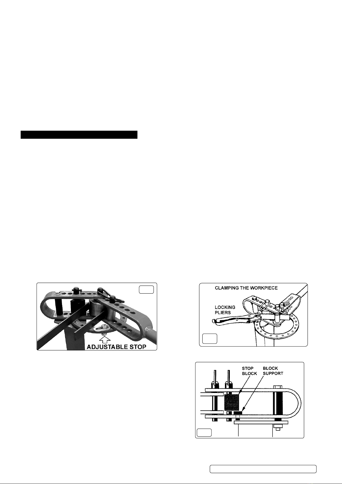
Using the xed or adjustable stop. Further adjustments may be necessary but once you know the amount of rotation necessary to
achieve a particular angle this can be repeated by using the xed or adjustable stops provided. (See gs.3&11)
5.3. Multiple bends
When doing more than one bend, similar trial and error may be necessary to establish the correct relationship between bends. Mark
the bend positions on the trial workpiece. Make the bends and then measure the distance between them. Make any necessary
adjustments to the measurement to achieve the desired result.
5.4. Bend sequence
Where a number of bends are to be made in the same piece of metal attention should be paid to the order in which the `
bends are made to achieve the nished part. You may need to re-orientate the workpiece in the bender by reversing it or inverting
its position. If necessary the bender can be disassembled to remove or reposition a complex bend conguration.
5.5. Clamping the workpiece
Generally the workpiece is automatically clamped in place by the action of the bender. In certain instances some slippage may occur
e.g. when forming material around a large die. This can be eliminated by clamping the end of the material with locking pliers which
then act against the stop block to prevent the material moving. (See g.4)
5.6. Making radiused bends
Do not try to bend material more than 1/4” thick around the centre pin. The 1” die must be used.
5.8 Use of the ‘stop block’
The ‘stop block’ prevents the material from rotating in the bender while a
forming die mounted in the handle bends the material either round the
centre pin or around another die that has been installed on the centre pin.
5.9 Orientation of the ‘stop block’
The ‘stop block’ can be placed in several orientations allowing additional
exibility in the positioning of the workpiece in relation to the forming dies.
Its relationship to the workpiece is altered by rotating it on the hinge pin
or by turning it upside down on the pin and rotating it. However, only the
four orientations shown in g.5 should be used for bending. No matter
which face is against the workpiece, the pin through the block should
always be positioned to the right of the block centre otherwise the block
may turn and the material will slip in the bender.
5.10 Position of the block support
The block support is used to position the stop block vertically in the ring assembly loop as shown in g.6. Install the support in the
appropriate loop hole where it will support the block but not interfere with the insertion of the hinge pin all the way through the the hole
in the block and into the hole in the lower part of the loop.
fig.4
fig.3
fig.6
PBB04.V2 & PBF04.V2 | Issue:1 10/11/17
Original Language Version
© Jack Sealey Limited

5.11 Installing the dies
Install in the centre of the bender the chosen die around which you are going to form the metal. Use a long
hinge pin to retain both the die and the handle as shown in g.7. Install the die which will do the forming into the handle loop and
retain it using the short hinge pin. The space between the two dies should be as small as possible whilst allowing the metal to pass
through.
5.12 Installing the stop block and block support
Rotate the handle anticlockwise to the approximate starting position as shown in g.7. Insert the metal to be formed in between the
dies. Now install the stop block and block support at one of the ve large holes in the ring assembly’s loop. You will have to determine
by trial and error which hole to use depending on the thickness of the material being bent, the size of the centre pin die, and the
orientation of the stop block. The block should be as close to the centre pin/die as the material will allow. Retain the stop block with a
long hinge pin.
WARNING! When making a bend or partial bend close to the end of a piece of material the bending force you are exerting on
the handle may suddenly be released as the bending die in the handle rolls off the end of the material. Watch the progress of
the die as it moves towards the end of the material and be prepared to release the pressure on the handle.
5.13 Making a bend (Before making a bend check that the bender is still rmly attached to the bench or oor. The oor should be clean
and dry and free from loose material. Wear non slip shoes and check that the area is clear of personnel and will remain clear whilst
you are executing the bend.)
If required, clamp the workpiece as shown in g.4. Exert just enough pressure on the handle to hold the material steady in the
bender and check that the material is level. Make the bend with steady and even pressure until you reach the desired nishing point
as indicated in g.8. ( As a rough guide to initially determine an angle when bending around a centrally mounted die there are 16.36
degrees between the holes in the ring.) Measure the angle bent and make any necessary adjustments.
5.14 Installing the sharp angle bend attachment
The sharp angle bend attachment has only one correct orientation as shown in g.10. and should be installed with the block support
underneath it to raise it to the correct position vertically within the loop. Counting from the outside of the loop towards the centre of the
bender place the block support in the third lower hole. Rest the sharp bend attachment on the block support and secure it by dropping
a long hinge pin through the fourth upper hole and all the way through the hole in the attachment into the hole in the lower part of the
loop. The longer ‘tail’ of the attachment should now be resting to the left of the loop spacer as shown in g.10
5.15 Installing the handle
Counting from the outside of the handle loop towards the centre of the bender align the sixth hole in the handle with the centre pivot
hole of the bender. Secure the handle by dropping a long hinge pin through both loops.
5.16 Installing the handle die
Install the smallest die in the last hole in the handle loop as shown in g.11 using a short hinge pin.
fig.11
fig.13
fig.5 fig.7
fig.10
fig.9
fig.8
PBB04.V2 & PBF04.V2 | Issue:1 10/11/17
Original Language Version
© Jack Sealey Limited

5.17 Preparation of workpiece
Mark the position of the bend or bends onto the material. These marks will represent the inside of each bend and therefore may be on
different sides of the material depending on the shape of the item you are making. ( If you are making two right angle bends on the
same side of the material, make the marks 3mm further apart than the desired inside dimension after the bend.)
5.18 Making a bend.
( Before making a bend check that the bender is still rmly attached to the bench or oor. The oor should be clean and dry and free
from loose material. Wear non slip shoes and check that the area is clear of personnel and will remain clear whilst you are executing
the bend.) Slide the material into the bender so that the rst marked out bend is aligned with the tip of the sharp angle attachment.
(The material face that is touching the tip of the sharp angle attachment will become the inside of the bend. See g.13 which shows
the action of the bender when using the sharp angle attachment.)
Exert just enough pressure on the handle to hold the material steady in the bender and check that the material is level. Make the bend
with steady and even pressure until you reach the desired nishing point as indicated in g.12. Measure the angle and make any
necessary adjustments. Once the required movement for a particular angle has been established it can be repeated by the use of the
xed stop as shown in gs.11 & 12. If the nish point of a bend falls between two holes use the adjustable stop as shown in g.3.
EXAMPLE -
DOUBLE TUBE CLAMP
5.19 Below is illustrated a simple example of the bend sequence required to make a simple pipe clamp using both methods of bending.
The rst two bends are around a 1” die mounted on the centre pin with the stop block in place. The last two bends are made using the
sharp angle attachment. To insert the workpiece in C & D it will be necessary to temporarily remove the centre pin. Dis-assemble the
handle to remove the nished piece.
Sealey Group, Kempson Way, Suffolk Business Park, Bury St Edmunds, Suffolk. IP32 7AR
01284 757500 01284 703534 sales@sealey.co.uk www.sealey.co.uk
ENVIRONMENT PROTECTION
Recycle unwanted materials instead of disposing of them as waste. All tools, accessories and packaging should be sorted, taken to
a recycling centre and disposed of in a manner which is compatible with the environment. When the product becomes completely
unserviceable and requires disposal, drain any fluids (if applicable) into approved containers and dispose of the product and fluids
according to local regulations.
Note: It is our policy to continually improve products and as such we reserve the right to alter data, specifications and component parts without prior
notice.
Important: No Liability is accepted for incorrect use of this product.
Warranty: Guarantee is 12 months from purchase date, proof of which is required for any claim.
fig. 12 fig.13
PBB04.V2 & PBF04.V2 | Issue:1 10/11/17
Original Language Version
© Jack Sealey Limited
This manual suits for next models
1
Table of contents
Other Sealey Construction Equipment manuals

Sealey
Sealey PH20.v4 User manual

Sealey
Sealey SC10 User manual

Sealey
Sealey PFC301 User manual

Sealey
Sealey SSC450 User manual

Sealey
Sealey PH10 User manual

Sealey
Sealey WF10Q User manual

Sealey
Sealey PBF04 User manual

Sealey
Sealey WD10 User manual

Sealey
Sealey PH20 User manual

Sealey
Sealey PCB32 User manual

Sealey
Sealey PH10.V4 User manual

Sealey
Sealey 500KC.V2 User manual

Sealey
Sealey SSCL.1 User manual

Sealey
Sealey SSC900 User manual

Sealey
Sealey PH10.V6 User manual

Sealey
Sealey PBS90.V2 User manual

Sealey
Sealey PBS90.V2 User manual

Sealey
Sealey DF760.V2 User manual

Sealey
Sealey AUTO SERVICE AK5061 User manual

Sealey
Sealey WF10 User manual