Sealey HVLP02 User manual

Familiarise yourself with the application, limitations and potential hazards peculiar to the spray gun.
WARNING!Disconnect the spray gun from the air supply before changing accessories, servicing or performing any maintenance.
Maintain the spray gun in good condition (use an authorised service agent).
Replace or repair damaged parts. Use recommended parts only. Unauthorised parts may be dangerous and will invalidate the warranty.
Keep the spray gun clean for best and safest performance.
Ensure that the compressed air system can supply the spray gun air consumption (14.5cfm).
Wear approved safety respiratory protection and safety eye goggles.
If spraying isocynate based finisher, wear approved respirator/clean air breathing apparatus and cover exposed skin with latex gloves and an
impervious hooded coverall.
Remove ill-fitting clothing. Remove ties, watches, rings and other loose jewellery and tie back long hair.
Locate the spray gun in a suitable work area. Keep area clean and tidy and free from unrelated materials and ensure that there is adequate
ventilation and lighting.
Keep children and unauthorised persons away from the work area.
When not in use, ensure that the air supply is turned off.
Avoid unintentional operation of spray gun.
DO NOT point spray gun at yourself, other persons or animals.
DO NOT direct air from the air hose at yourself, other persons or animals.
DO NOT carry the spray gun by the hose, or yank the hose from the air supply.
DO NOT exceed the maximum air pressure of 43psi.
DO NOT use the spray gun for any purpose other than that for which it is designed.
DO NOT allow untrained persons to operate the spray gun.
DO NOT get the spray gun wet or use in damp or wet locations or in areas where there is condensation.
DO NOT operate the spray gun if any parts are missing or damaged as this may cause failure and/or personal injury.
When not in use, disconnect the spray gun from the air supply, clean thoroughly and store safely.
Model: ........................... HVLP02
Standard set-up:......................1.7mm
Available set-ups: ..............1.3, 1.4, 2.0mm
Air pressure: ....................... 30-43psi
Air consumption:.....................14.5cfm
Pot Capacity: .......................1000ml
Suction feed spray guns designed for the professional bodyshop. Features air and paint ow controls for ne adjustment of spray pattern. HVLP
Technology and precision engineering delivers consistent and unrivalled results. Suitable for water based paints.
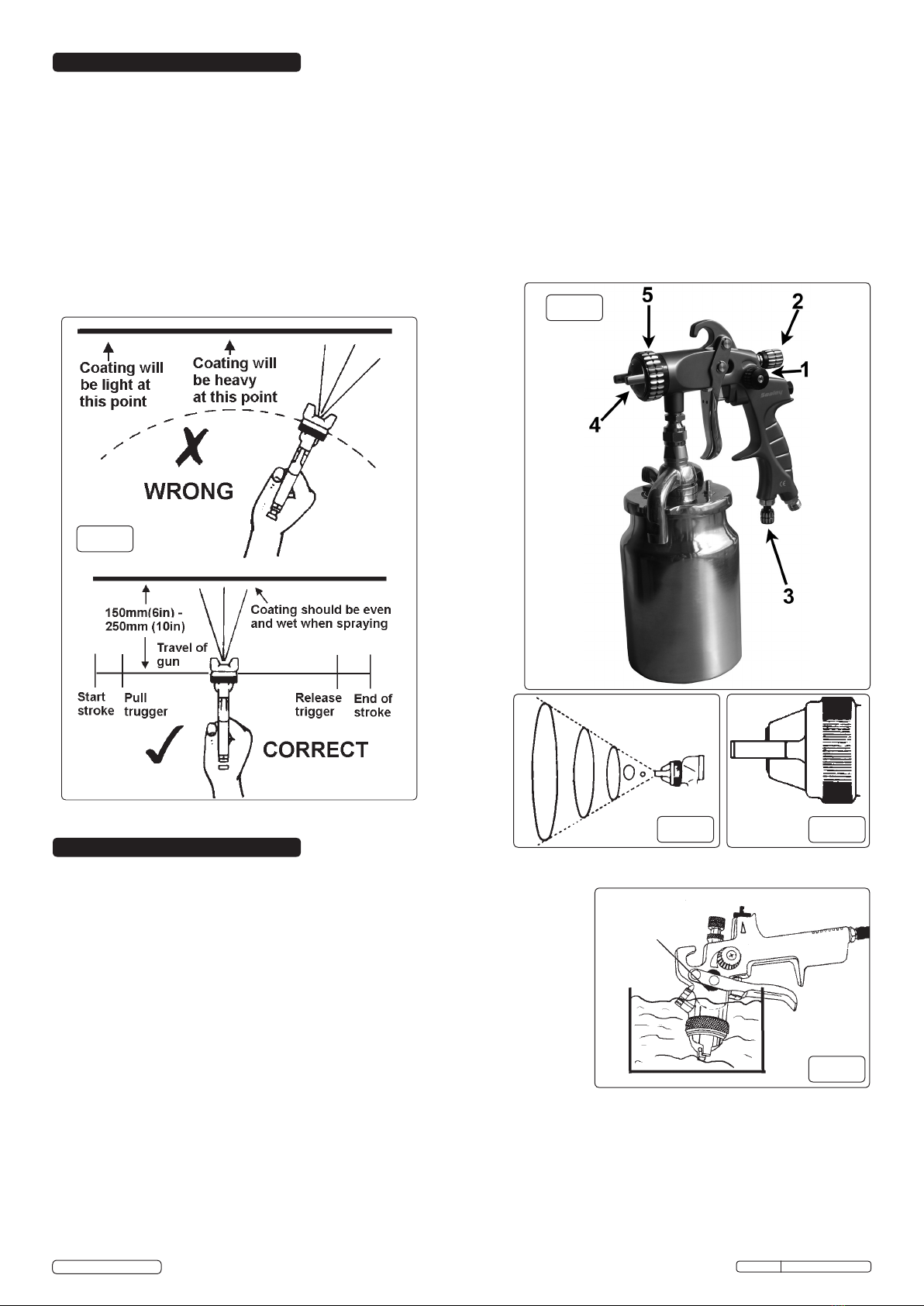
fig.1
4.1. Air Supply
Recommended hook-up procedure is shown in fig.1.
4.1.1. Ensure spray gun air valve (or trigger) is in the off position before connecting to the air supply.
4.1.2. You will require an air pressure of 30 to 43psi, and an air flow according to specification.
4.1.3. WARNING! Ensure the air supply is clean and does not exceed 43psi while operating the spray gun. Too high an air pressure and/or
unclean air will shorten the product life due to excessive wear, and may be dangerous causing damage and/or personal injury.
4.1.4. Drain the air tank daily. Water in the air line will ruin the paint finish and damage the spray gun.
4.1.5. Clean air inlet filter weekly.
4.1.6. Line pressure should be increased to compensate for unusually long air hoses (over 8 metres). The minimum hose diameter should be
1/4” I.D. and fittings must have the same inside dimensions.
4.1.7. Keep hose away from heat, oil and sharp edges. Check hose for wear, and make certain that all connections are secure.
4.2. Couplings
Vibration may cause failure if a quick change coupling is connected directly to the spray gun. To overcome this, connect a leader hose to
the spray gun. A quick change coupling may then be used to connect the leader hose to the air line recoil hose. See figs.1 & 2.
fig.2
INSTRUCTIONS FOR:
HVLP SUCTION FEED SPRAY GUN
1.7MM SET-UP
MODEL NO:HVLP02
IMPORTANT: PLEASE READ THESE INSTRUCTIONS CAREFULLY. NOTE THE SAFE OPERATIONAL REQUIREMENTS, WARNINGS & CAUTIONS. USE THE
PRODUCT CORRECTLY AND WITH CARE FOR THE PURPOSE FOR WHICH IT IS INTENDED. FAILURE TO DO SO MAY CAUSE DAMAGE AND/OR PERSONAL
INJURY AND WILL INVALIDATE THE WARRANTY. KEEP THESE INSTRUCTIONS SAFE FOR FUTURE USE.
Thank you for purchasing a Sealey product. Manufactured to a high standard, this product will, if used according to these instructions,
and properly maintained, give you years of trouble free performance.
1. SAFETY
2. INTRODUCTION
3. SPECIFICATION
4. AIR SUPPLY
HVLP02 Issue: 1 - 21/08/14
Original Language Version
© Jack Sealey Limited

5.1. Take filter and slide onto the end of the paint pickup tube.
5.2. For best results, the gun should be held perpendicular to the surface being sprayed and moved parallel to it. Start the stroke before
squeezing the trigger and release the trigger before finishing the stroke. This will enable you to accurately control the gun and material (fig.3).
5.3. Spray from a distance of about 150mm to 250mm depending on the material and the atomizing pressure. The material deposited should
always be even and wet. Each stroke must overlap the preceding stroke to obtain a uniform finish. To reduce over-spray and obtain
maximum efficiency, spray with the lowest possible atomizing air pressure.
5.4. Controlling the fan spray and the fluid.
a) Use the needle (paint) adjustment knob (fig.4.2) to increase or decrease the amount of paint flow.
b) The atomizing air flow is controlled by knob (fig.4.1). The volume of air input is controlled by knob (fig.4.3).
c) As width of spray is increased more material must pass through the gun to obtain the same coverage on the increased area.
d) Turn the air nozzle (fig.4.4) to achieve a horizontal or vertical fan spray. Lock the nozzle with retaining ring (fig.4.5).
The spray pattern of the gun is variable from round to flat with all patterns in between. In normal operation, the wings on the
nozzle are horizontal as fig.5. This provides a vertical fan-shaped pattern which gives maximum uniform and even coverage when
moving the gun back and forth, parallel to the work surface (fig.6).
FOR OPTIMUM PERFORMANCE IT IS VERY IMPORTANT TO ENSURE THE GUN IS CORRECTLY CLEANED AFTER EACH USE.
Disconnect from the air supply before attempting any cleaning or maintenance.
6.1. Cleaning the gun
6.1.1. Immerse the front end of the gun only in solvent. The solvent should just cover the
fluid connection (fig.7).
6.1.2. Use the bristle brush (fig.8) and solvent to wash off accumulated paint.
6.1.3. Do not immerse the entire gun in solvent as this will cause lubricants on the rubber
seals to dissolve. Dirty solvent may also clog narrow passages in the gun.
6.1.4. Flush the gun through with clean solvent.
6.1.5. Wipe the outside of the gun with a dampened solvent rag.
6.2. Air nozzle, fluid nozzle and needle assembly
6.2.1. To clean the nozzles, soak them in solvent to dissolve any dried material then blow them
clean with air. Handle all nozzles carefully and do not make any alterations in the gun.
6.2.2. If you need to probe the holes in the nozzles, be sure to use a tool that is softer than
brass; do not use metal instruments.
6.2.3. Adjust the fluid needle valve so that when the gun is triggered, air flow occurs before fluid flow.
6.3. Maintenance
Disassemble using the supplied spanner and socket (fig.8)
Take care when re-assembling. Firstly screw parts hand tight to avoid cross-threading then tighten with spanner. If a part cannot easily be
turned by hand, check that you have the correct part, or unscrew, realign and try again. DO NOT use excessive force when re-assembling.
6.3.1. Lubricate the gun daily with a light machine oil.
6.3.2. If you change the nozzle size, ensure the complete nozzle set is exchanged. Insert paint nozzle before putting the paint needle in.
Keep solvent level
below packing
5. OPERATION
6. CLEANING
HVLP02 Issue: 1 - 21/08/14
Original Language Version
© Jack Sealey Limited
fig.3
fig.4
fig.5 fig.6
fig.7

VIEW OF PROBLEM POSSIBLE REASON FOR PROBLEM SOLUTION
Dried material in a dirty side port restricts passage
of air. Greater flow of air from the cleaner side port
forces a fan pattern in the direction of the clogged
side.
Dissolve material in the side ports with solvent, then
blow the gun clean. DO NOT poke into the opening
with metal instruments.
Dried material around the outside of the fluid nozzle
tip restricts the passage of atomizing air at one
point through the centre opening of the air nozzle
and results in the pattern shown. This pattern can
also be caused by a loose air nozzle.
Remove the air nozzle and wipe off fluid tip using a
rag dampened with solvent. Tighten the air nozzle.
Material too thin or atomization air pressure too
high.
Regulate material viscosity or reduce air pressure.
Dirt between the fluid nozzle seat and body or
loosely installed fluid nozzle will cause the gun to
spit.
Remove the fluid nozzle, clean the back of the
nozzle and the nozzle seat in the gun body using a
rag dampened with thinner. Replace the nozzle and
secure it tightly against the body.
Atomised air flowing through the paint channel to
pot.
The paint nozzle is not tight enough. Air nozzle is
not completely screwed in.
Tighten, clean or replace parts accordingly.
A faulty spray is usually caused by improper cleaning or dried material around the fluid nozzle tip or in the air nozzle. Soak these parts in a solvent
that will soften the dried material and remove with a brush or a cloth. Never use metal instruments to clean the air or fluid nozzles. These parts are
carefully machined and any damage to them will cause a faulty spray. If either the air nozzle or fluid nozzle is damaged, the part must be replaced
before a perfect spray can be obtained.
Material bubbles or in paint cup.
Parts support is available for this product. To obtain a parts listing and/or diagram, please log on to www.sealey.co.uk,
email sales@sealey.co.uk or telephone 01284 757500.
HVLP02 Issue: 1 - 21/08/14
NOTE: It is our policy to continually improve products and as such we reserve the right to alter data, specifications and component parts without prior notice.
IMPORTANT: No liability is accepted for incorrect use of this product.
WARRANTY: Guarantee is 12 months from purchase date, proof of which will be required for any claim.
INFORMATION: For a copy of our latest catalogue and promotions call us on 01284 757525 and leave your full name and address, including postcode.
01284 757500
01284 703534
sales@sealey.co.uk
Sole UK Distributor, Sealey Group,
Kempson Way, Suffolk Business Park,
Bury St. Edmunds, Suffolk,
IP32 7AR
www.sealey.co.uk
Original Language Version
© Jack Sealey Limited
Environmental Protection
Recycle unwanted materials instead of disposing of them as waste. All tools, accessories and packaging should be
sorted, taken to a recycling centre and disposed of in a manner which is compatible with the environment.
When the product becomes completely unserviceable and requires disposal, drain off any fluids (if applicable)
into approved containers and dispose of the product and the fluids according to local regulations.
7. TROUBLESHOOTING
fig.8
Table of contents
Other Sealey Paint Sprayer manuals

Sealey
Sealey SSG1P.V2 User manual

Sealey
Sealey SSG2.V3 User manual

Sealey
Sealey HVLP-750.V2 User manual

Sealey
Sealey PROFESSIONAL GOLD Series User manual

Sealey
Sealey S717 User manual

Sealey
Sealey SSG401.V2 Firmware update

Sealey
Sealey SCSG06 User manual

Sealey
Sealey POWER PRODUCTS SG139.V2 User manual

Sealey
Sealey S713G Manual

Sealey
Sealey SSG501.V3 User manual

Sealey
Sealey SG139.V2 User manual

Sealey
Sealey Workshop Series User manual

Sealey
Sealey SSG1/GX User manual

Sealey
Sealey SM24/1.V2 User manual

Sealey
Sealey HVLP732 User manual

Sealey
Sealey HVLP-79/P.V3 User manual

Sealey
Sealey SCSG2R User manual

Sealey
Sealey SSA2 User manual

Sealey
Sealey SG10.V2 User manual

Sealey
Sealey HVLP736 User manual