manuals.online logo
Brands
  1. Home
  2. •
  3. Brands
  4. •
  5. Sealey
  6. •
  7. Tools
  8. •
  9. Sealey VSE127H05 User manual

Sealey VSE127H05 User manual

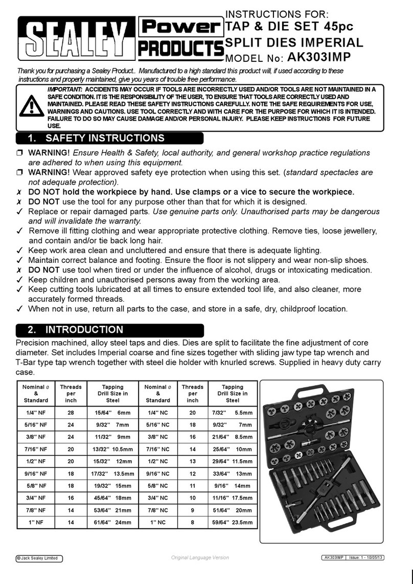
INSTRUCTIONS FOR:
Ball Joint Removal/Installation Set
(Mercedes Sprinter)
Model No: VSE127H05
1. SAFETY INSTRUCTIONS
2. INTRODUCTION & SPECIFICATION
Thank you for purchasing a Sealey product. Manufactured to a high standard this product will, if used according to these instructions and properly maintained, give
you years of trouble free performance.
IMPORTANT: READ THESE INSTRUCTIONS CAREFULLY. NOTE THE SAFE OPERATIONAL REQUIREMENTS, WARNINGS AND CAUTIONS.
USE THE TOOL CORRECTLY AND WITH CARE FOR THE PURPOSE FOR WHICH IT IS INTENDED. FAILURE TO DO SO MAY CAUSE DAMAGE
AND/OR PERSONAL INJURY AND WILL INVALIDATE THE WARRANTY. PLEASE KEEP INSTRUCTIONS SAFE FOR FUTURE USE.
 WARNING! Ensure Health and Safety, local authority and general
workshop practice regulations are adhered to when using tools.
 DO NOT use tools if damaged.
 Maintain tools in good and clean condition for best and safest
performance.
 Ensure that a vehicle which has been jacked up is adequately
supported with axle stands and that the wheels are chocked.
 Ensure that the rear axle is adequately supported, refer to the
vehicle manufacturer’s service instructions, or a proprietary
manual.
 Wear approved eye protection. A full range of personal safety
equipment is available from your Sealey dealer.
 Wear suitable clothing to avoid snagging. Do not wear jewellery
and tie back long hair.
DO NOT use air tools to operate the force screw.
IMPORTANT: The force screw must be kept well lubricated.
IMPORTANT: This manual is provided as a guide only, refer to
the vehicle manufacturer’s service instructions, or a proprietary
manual, to establish the current procedure and data.
 WARNING! Failure to heed safety and warning instructions may
result in damage and/or personal injury and will invalidate the
warranty.
 WARNING! The warnings, cautions & instructions referred
to in this manual cannot cover all possible conditions and
situations that may occur. It must be understood that
common sense and caution are factors which cannot be
built into this product, but must be applied by the operator.
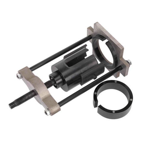
Use in conjunction with Sealey Hydraulic Ball Joint Remover/Installer
Kit (Model No. VSE127H). Essential tool for removal/installation of the
Mercedes Sprinter front lower ball joint in situ. Includes all necessary
adaptors.
SPECIFICATION:
Model No. ....................................................................... VSE127H05
Model No. of associated Tool .............................................. VSE127H
Ball joint OE Number....................................................... 9013330727
Application - Mercedes............... Sprinter 901, 902, 903, 904 (95-on)
3. OPERATION
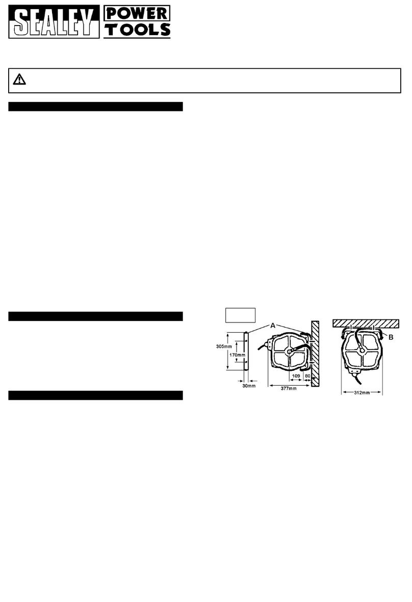
NOTE! Pictures taken with the lower arm / wishbone removed from
vehicle for clarity only.
NOTE! Before installing the new ball joint, refer to the vehicle
manufacturer’s service instructions, or a proprietary manual, to
establish the correct data and procedures.
VSE127H05 Issue No. 1 - 10/11/09

ALWAYS KEEP FORCE SCREW
WELL LUBRICATED.
DO NOT USE AIR TOOLS
Original Language Version
Fig.1
Fig.2
VSE127H05 Issue No. 1 - 10/11/09
NOTE: It is our policy to continually improve products and as such we reserve the right to alter data, specifications and component parts without prior notice.
IMPORTANT: No liability is accepted for incorrect use of this product.
WARRANTY: Guarantee is 12 months from purchase date, proof of which will be required for any claim.
INFORMATION: For a copy of our latest catalogue and promotions call us on 01284 757525 and leave your full name and address, including postcode.
Sole UK Distributor, Sealey Group,
Kempson Way, Suffolk Business Park,
Bury St. Edmunds, Suffolk,
IP32 7AR
01284 757500
01284 703534
sales@sealey.co.uk
www.sealey.co.uk
Web
email
Original Language Version
Fig.3
Fig.4
3.1 Ball Joint Removal. To remove the ball joint you will need to
use adaptors A & B in conjunction with Sealey Hydraulic Ball
Joint Remover/Installer Kit (Model No. VSE127H).
3.1.1 Referring to the vehicle manufacturers servicing information
disassemble the necessary suspension and steering
components to gain access to the ball joint for removal.
3.1.2 Rotate the hydraulic unit anticlockwise within the press frame
until the bottom of the unit is level with the underside of the top
bar. Ensure that the black ring is properly seated in the base of
the press (see fig.1-Z) and place adaptor (B) into the ring with
the narrower section upwards.
3.1.3 Holding the hydraulic unit, take the press to the exposed ball
joint and introduce it into adaptor (B). Lift the press so that
adaptor (B) bears directly onto the casting that holds the ball
joint. See ‘X’ inset in fig.3.
3.1.4 Slide adaptor (A) into position on the top of the ball joint itself
ensuring that the surface with the indent in it is uppermost. Turn
the handle on the hydraulic unit clockwise so that the ram
descends and the steel ball at the end of the ram enters the
indent. Continue turning the handle until the whole assembly is
firmly clamped onto the ball joint housing.
3.1.5 Before applying pressure to the ball joint ensure that the adaptors
are correctly seated as shown in the inset diagram in fig.3.
3.1.6 Continue to turn the ram handle slowly clockwise until the ball
joint is fully ejected. Be prepared for the sudden release of the
ball joint at which point the assembly will become unstable.
3.1.7 Turn the ram handle anticlockwise to back off the ram. Remove
adaptor (A) first, then remove the whole assembly from the ball
joint housing.
3.2 Ball Joint Installation. To install the ball joint you will need to
use adaptors C & D in conjunction with Sealey Hydraulic Ball
Joint Remover/Installer Kit (Model No. VSE127H).
3.2.1 Rotate the hydraulic unit anticlockwise within the press frame
until the bottom of the unit is level with the underside of the top
bar. Ensure that the black ring is properly seated in the base of
the press (see fig.1-Z) and place the closed end of adaptor (D)
into the ring. Place the threaded stub of the new ball joint (J) into
the open end of adaptor (D) so that the body of the ball joint sits
inside the flange in the top of the adaptor.
3.2.2 Holding the hydraulic unit, take the press to the exposed ball
joint housing. Lift the press so that the body of the ball joint (J) is
positioned ready to enter the ball joint housing.
3.2.3 Slide adaptor (C) into position on the top of the ball joint housing
ensuring that the surface with the indent in it is uppermost as
seen in the inset diagram in fig.4. Turn the handle on the
hydraulic unit clockwise so that the ram descends and the steel
ball at the end of the ram enters the indent. Continue turning the
handle until the whole assembly is firmly clamped onto the ball
joint housing.
3.2.4 Before applying pressure to insert the ball joint (J) ensure that the
ball joint is correctly aligned with the opening in the housing and
the adaptors are correctly seated as shown in the inset diagram
in fig.4.
3.2.5 Continue to turn the ram handle slowly clockwise until the ball
joint is fully inserted.
3.2.6 Turn the ram handle anticlockwise to back off the ram. Remove
adaptor (C) first, then remove the whole assembly from the ball
joint housing.
Other Sealey Tools manuals

Sealey Professional TOOLS SX300.V2 User manual

Sealey

Sealey Professional TOOLS SX300.V2 User manual

Sealey VSE127H User manual

Sealey

Sealey VSE127H User manual

Sealey VS0204C4 User manual

Sealey

Sealey VS0204C4 User manual

Sealey sa12/S.v2 User manual

Sealey

Sealey sa12/S.v2 User manual

Sealey SA6501 User manual

Sealey

Sealey SA6501 User manual

Sealey TC965.V2 User manual

Sealey

Sealey TC965.V2 User manual

Sealey VSE3038 User manual

Sealey

Sealey VSE3038 User manual

Sealey VS4830 User manual

Sealey

Sealey VS4830 User manual

Sealey AUTO SERVICE VS004.V2 User manual

Sealey

Sealey AUTO SERVICE VS004.V2 User manual

Sealey TSTVRK User manual

Sealey

Sealey TSTVRK User manual

Sealey AK2951 User manual

Sealey

Sealey AK2951 User manual

Sealey Auto Service PFT12 User manual

Sealey

Sealey Auto Service PFT12 User manual

Sealey hp1000.V2 User manual

Sealey

Sealey hp1000.V2 User manual

Sealey VS0110 User manual

Sealey

Sealey VS0110 User manual

Sealey SUPERSNAP RE83/10 User manual

Sealey

Sealey SUPERSNAP RE83/10 User manual

Sealey VS0216 User manual

Sealey

Sealey VS0216 User manual

Sealey VS5285 User manual

Sealey

Sealey VS5285 User manual

Sealey SA11/S User manual

Sealey

Sealey SA11/S User manual

Sealey SUPERSNAP RE83/10/SK User manual

Sealey

Sealey SUPERSNAP RE83/10/SK User manual

Sealey WBR01 User manual

Sealey

Sealey WBR01 User manual

Sealey POWER PRODUCTS SA88.V4 User manual

Sealey

Sealey POWER PRODUCTS SA88.V4 User manual

Sealey SA821.V2 User manual

Sealey

Sealey SA821.V2 User manual

Sealey SA88.V3 User manual

Sealey

Sealey SA88.V3 User manual

Sealey AK303IMP User manual

Sealey

Sealey AK303IMP User manual

Popular Tools manuals by other brands

Stanley 55 How to use

Stanley

Stanley 55 How to use

Cocraft HL-W-30 Assembly

Cocraft

Cocraft HL-W-30 Assembly

EINHELL DTA 25/1 Operating and maintenance instructions

EINHELL

EINHELL DTA 25/1 Operating and maintenance instructions

Franklin AFT25 manual

Franklin

Franklin AFT25 manual

Duratool D03291 quick start guide

Duratool

Duratool D03291 quick start guide

Northern Industrial Tools 816400 owner's manual

Northern Industrial Tools

Northern Industrial Tools 816400 owner's manual

Alemite 8597 Service guide

Alemite

Alemite 8597 Service guide

Makita BV4500-118 instruction manual

Makita

Makita BV4500-118 instruction manual

TapeTech MudRunner 14TT Operation and maintenance guide

TapeTech

TapeTech MudRunner 14TT Operation and maintenance guide

BGS technic 62637 manual

BGS technic

BGS technic 62637 manual

Freeman PP123 manual

Freeman

Freeman PP123 manual

VonHaus 3500046 ASSEMBLY & USE

VonHaus

VonHaus 3500046 ASSEMBLY & USE

BGS technic 6679 instruction manual

BGS technic

BGS technic 6679 instruction manual

Signode Josef Kihlberg R555PN operating instructions

Signode

Signode Josef Kihlberg R555PN operating instructions

KUKKO KS-22-01 instruction manual

KUKKO

KUKKO KS-22-01 instruction manual

Mityvac Fluid evacuator plus User and maintenance instructions

Mityvac

Mityvac Fluid evacuator plus User and maintenance instructions

SCHUNK VERO-S NSL mikro 50-13 Translation of the original operating manual

SCHUNK

SCHUNK VERO-S NSL mikro 50-13 Translation of the original operating manual

Ryobi EHT150RG Owner's operating manual

Ryobi

Ryobi EHT150RG Owner's operating manual

manuals.online logo
manuals.online logoBrands
  • About & Mission
  • Contact us
  • Privacy Policy
  • Terms and Conditions

Copyright 2025 Manuals.Online. All Rights Reserved.