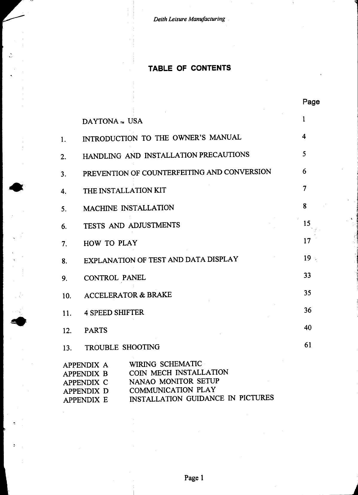
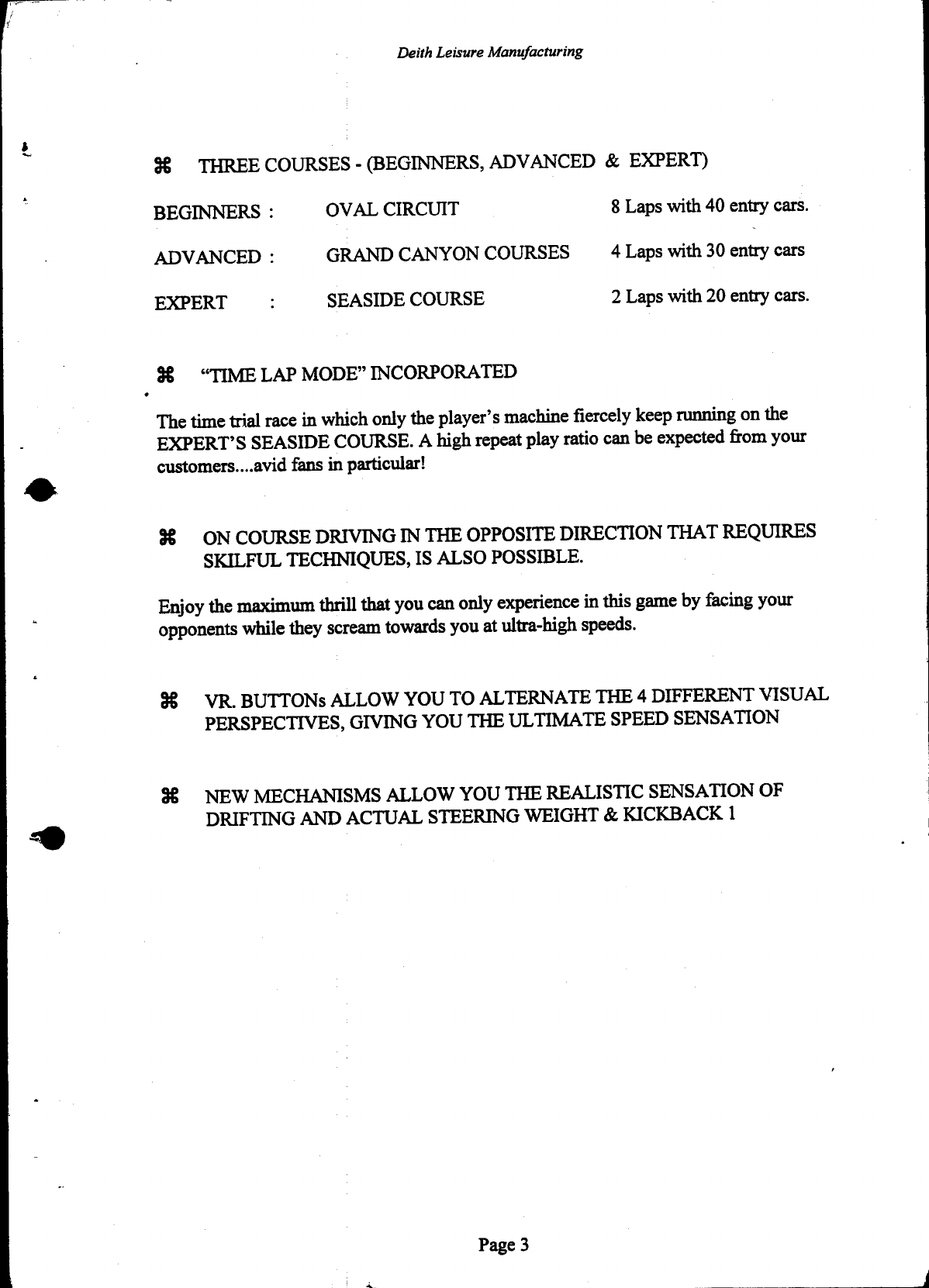
Sega Daytona USA User manual
Other Sega Arcade Game Machine manuals

Sega
Sega Sonic Allstarts User manual

Sega
Sega Outrun 2 Supplement

Sega
Sega BG-X005SGA User manual

Sega
Sega Daytona Championship USA User manual

Sega
Sega House of the Dead User manual

Sega
Sega PIRATES of MONSTER ISLAND User manual

Sega
Sega Giant Plants vs Zombies The Last Stand User manual

Sega
Sega Crazy Taxi High Roller Supplement

Sega
Sega NAOMI 2 User manual

Sega
Sega Ghost Squad Deluxe User manual

Sega
Sega UFO CATCHER User manual

Sega
Sega Virtua Cop 3 Deluxe Type User manual

Sega
Sega Showdown User manual

Sega
Sega Double Spin User manual

Sega
Sega Luigi's Mansion Arcade Application guide

Sega
Sega Ghost Squad User manual

Sega
Sega AFTER BURNER CLIMAX User manual

Sega
Sega Let's Go ISLAND! User manual

Sega
Sega Cows Might Fly User manual

Sega
Sega Rally 2 DX User manual


Popular Arcade Game Machine manuals by other brands

Universal Space
Universal Space COCONUT BASH Operation manual

Bay-Tek
Bay-Tek EVOLVE installation guide

Global VR
Global VR America's Army Operation & service manual

Atronic
Atronic Cashline installation manual

Universal Space
Universal Space Checky Monkey Operation manual

Bay-Tek
Bay-Tek Skee Ball 1908 Alley Service manual

Aristocrat Technologies
Aristocrat Technologies Mars X Upright Service manual

Family Fun Companies
Family Fun Companies Reactor Parts, Service and Distribution

Universal Space
Universal Space FRUIT MANIA Extreme Operation manual

falgas
falgas CARRUSEL FIESTA user guide

Konami
Konami DanceDanceRevolution Operator's manual

Bay-Tek
Bay-Tek quik drop Service manual

Bandai Namco
Bandai Namco PAC-MAN BATTLE ROYALE CHOMPIONSHIP DELUXE Operation manual

Adrenaline
Adrenaline Flying Tickets Operation & service manual

Swinks
Swinks Stern Pinball Ghostbusters manual

Innovative Concepts in Entertainment
Innovative Concepts in Entertainment MONOPOLY ROLL-N-GO Service manual

jakar
jakar SPEED CARS Operator's manual

Carmelli
Carmelli HAT TRICK NG1015H Assembly instructions