TF D01M 0001 AO 021711A0 060213 MUi-10rev060213
&2//(*$0(17, (/(775,&, (/(&75,&$/ :,5,1*6 (/(.752$16&+/h66(
%5$1&+(0(176e/(&75,48(6&21(;,21(6(/(&75,&$6
4
02725(
Pos. ESTATE: Sempre acceso
Pos. OFF: Spento
Pos. INVERNO: Sempre acceso con
Termostato di mandata
02725
Pos. SUM.: Alwais turned on
Pos. OFF: Turned off
Pos. WIN.: Always on, with termostat of
sent
(/(77529$/92/(
Pos. ESTATE: E.V. freddo termostatata
Pos. OFF: Tutte spente
Pos. INVERNO: E.V. caldo termostatata
(/(&7529$/9(
Pos. SUM.: E.V. cold termostat
Pos. OFF: All turned off
Pos. WIN.: E.V. heat thermostat
',6326,7,9,&21752//$7,
- N1 Motore a 3 velocità
- N2 Elettrovalvole
- Selezione Estate /inverno
- Termostato di mandata
&21752//(''(9,&(6
-N°1 3-speeds fan
-N°2 Electrovalves
-Summer/winter selection
-Termostat of sent
02725
Pos. SOMMER: immer eingeschaltet
Pos. OFF: abgeschaltet
Pos. WINTER: immer mit
Förderleistungsther- mostat
eingeschaltet
027(85
Pos. ÉTÉ : Toujours allumé
Pos. ARRÊT : Éteint
Pos. HIVER : Toujours allumé avec
thermostat de refoulement
(/(.7529(17,/(
Pos. SOMMER: zeitgesteuertes E.V. (Kälte)
Pos. OFF: alle E.V. abgeschaltet
Pos. WINTER: zeitgesteuertes E.V.
(Wärme)
e/(&7529$11(6
Pos. ÉTÉ : E.V. pour froid thermostatée
Pos. ARRÊT : Toutes éteintes
Pos. HIVER : E.V. pour chaud thermostatée
*(67(8(57(*(5b7(
- N1 Dreigeschwindigkeitsmotor
- N2 Elektroventile
- Wahl Sommer/Winter
- Förderleistungsthermostat
',6326,7,)6&2175Ð/e6
- N1 Moteur à 3 vitesses
- N2 Électrovannes
- Sélection été/hiver
- Thermostat de refoulement
02725
Pos. VERANO: Siempre encendido
Pos. OFF: Apagado
Pos. INVIERNO: Siempre encendido con
termostato de envio
(/(&7529$/98/$6
Pos. VERANO: E.V. frío bajo control
Pos. OFF: Todas apagadas
Pos. INVIERNO: E.V. caliente bajo control
',6326,7,926&21752/$'26
- N1 Motor a 3 velocidades
- Selección Verano/Invierno
- N2 Electroválvulas
- Termostato de envio
4
N
3
L
50/60HzL
230V~ N
11
10
8
9
7
5
6
T.M.
M~ III
II
I
COM
E.V.
E.V.
12
13 S.A.
S.A.
$
02725(
Pos. ESTATE: Sempre acceso
Pos. OFF: Spento
Pos. INVERNO: Sempre acceso
02725
Pos. SUM.: Alwais turned on
Pos. OFF: Turned off
Pos. WIN.: Alwais turned on
(/(77529$/92/(
Pos. ESTATE: E.V. freddo termostatata
Pos. OFF: Tutte spente
Pos. INVERNO: E.V. caldo termostatata
(/(&7529$/9(
Pos. SUM.: E.V. cold termostat
Pos. OFF: All turned off
Pos. WIN.: E.V. heat termostat
',6326,7,9,&21752//$7,
- N1 Motore a 3 velocità
- N2 Elettrovalvole
- Selezione Estate /inverno
&21752//(''(9,&(6
-N°1 3-speeds fan
-N°2 Electrovalves
-Summer/winter selection
02725
Pos. SOMMER: immer eingeschaltet
Pos. OFF: abgeschaltet
Pos. WINTER: immer eingeschaltet
027(85
Pos. ÉTÉ : Toujours allumé
Pos. ARRÊT : Éteint
Pos. HIVER : Toujours allumé
(/(.7529(17,/(
Pos. SOMMER: zeitgesteuertes E.V. (Kälte)
Pos. OFF: alle E.V. abgeschaltet
Pos. WINTER: zeitgesteuertes E.V.
(Wärme)
e/(&7529$11(6
Pos. ÉTÉ : E.V. pour froid thermostatée
Pos. ARRÊT : Toutes éteintes
Pos. HIVER : E.V. pour chaud thermostatée
*(67(8(57(*(5b7(
- N1 Dreigeschwindigkeitsmotor
- N2 Elektroventile
- Wahl Sommer/Winter
',6326,7,)6&2175Ð/e6
- N1 Moteur à 3 vitesses
- N2 Électrovannes
- Sélection été/hiver
02725
Pos. VERANO: Siempre encendido
Pos. OFF: Apagado
Pos. INVERNO: Siempre encendido
(/(&7529$/98/$6
Pos. VERANO: E.V. frío bajo control
Pos. OFF: Todas apagadas
Pos. INVIERNO: E.V. caliente bajo control
',6326,7,926&21752/$'26
- N1 Motor a 3 velocidades
- Selección Verano/Invierno
- N2 Electroválvulas
N
L
4
3
5
III
7
6
8
M~ 10
II 9
I11
13
12
S.A.
S.A.
50/60HzL
230V~ N
COM
E.V.
E.V.
%
TF D01M 0001 AO 021711A0 060213 MUi-10rev060213
9
shown in Fig. 5.
7+(50267$72)6(17
The ’thermostat of sent’ function is used to inhibit the fan
operation whenever, but only in heating mode, the supply
water is not hot enough.
For this function to operate it is mandatory to wire a sensor
on the delivery water pipe or, as an alternative and to the
same terminals, a bimetallic thermostat.
In the event that the thermostat of sent 70 is not used it
will be necessary to apply a wire jumper between terminals
and .
,17(51$/(;7(51$/6(16256(/(&7,21
The thermostat leaves the factory already set for an internal
sensor work.
In those installations where a remote sensor is required,
please move jumper -3(located on the electronic board on
the right side of the selctors) into position $, as shown in
Fig. 6, then wire a 4.700 ohm @ 25°C NTC sensor with a
proper 'Beta' value at connector 6$ or, as an alternative, at
terminals and .
In case of doubts about the sensor to be connected, please
ask the producer.
7(&+1,&$/)($785(6
Power supply: 230V~ -15% +10% 50/60Hz
Power absorption: 3VA
Contact rating: 5 (1) A @ 250V~ SPDT
Sensor type: NTC 4.7K #C ±1% int.
(remote optional)
Regulation range: 5°C .. 35°C
Accuracy: ± 1°C
Resolution: 1°C
Hysteresis: 0.5°C
Operating temperature: 0°C .. 40°C
Storage temperature: -10°C .. +50°C
Humidity limits: 20% .. 80% RH (non condensing)
Protection grade: IP 30
Case: Material: ABS self-extinguishing V0
Color: Signal white (RAL 9003)
Size: 132 x 87 x 37 mm (W x H x D)
Weight: ~265 g
D :$51,1*
7R DGMXVW SURSHUO\ URRP WHPSHUDWXUH LQVWDOO WKH
WKHUPRVWDW IDU IURP KHDW VRXUFHV DLUVWUHDPV RU
SDUWLFXODUO\ FROG ZDOOV WKHUPDO EULGJHV :KHQ WKH
UHPRWH VHQVRU LV XVHG LQ FRQMXQFWLRQ ZLWK WKH
WKHUPRVWDW WKHQ WKLV QRWH PXVW EH DSSOLHG WR WKH
UHPRWHVHQVRULWVHOI
)RU UHPRWH YHUVLRQV DOO ZLULQJV PXVW EH PDGH XVLQJ
ZLUHV ZLWK PPð PLQLPXP FURVV VHFWLRQ DQG QRW
ORQJHU WKDQ P 'R QRW XVH VDPH GXFW IRU VLJQDO
ZLUHVDQGPDLQV
7KH DSSOLDQFH PXVW EH ZLUHG WR WKH HOHFWULF PDLQV
WKURXJKDVZLWFKFDSDEOHRIGLVFRQQHFWLQJDOOSROHVLQ
FRPSOLDQFHZLWKWKHFXUUHQWVDIHW\VWDQGDUGVDQGZLWK
DFRQWDFWVHSDUDWLRQRIDWOHDVWPPLQDOOSROHV
,QVWDOODWLRQ DQG HOHFWULFDO ZLULQJV RI WKLV DSSOLDQFH
PXVW EH PDGH E\ TXDOLILHG WHFKQLFLDQV DQG LQ
FRPSOLDQFHZLWKWKHFXUUHQWVWDQGDUGV
%HIRUHZLULQJWKHDSSOLDQFHEHVXUH WRWXUQ WKHPDLQV
SRZHURII
:$55$17<
In the view of a constant development of their products, the
manufacturer reserves the right for changing technical data
and features without prior notice. The consumer is
guaranteed against any lack of conformity according to the
European Directive 1999/44/EC as well as to the
manufacturer’s document about the warranty policy. The full
text of warranty is available on request from the seller.
(1*/,6+
29(59,(:
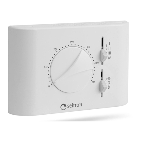
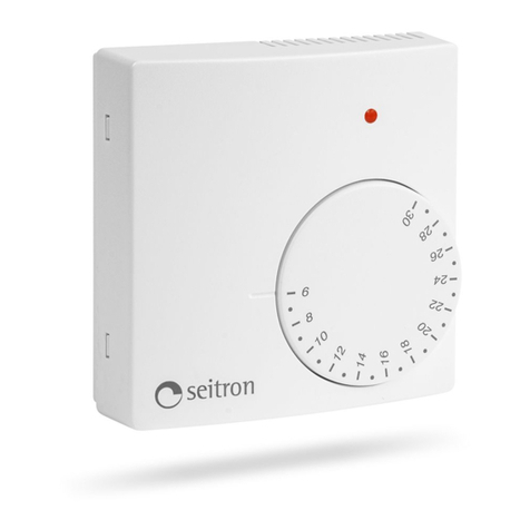
This device is a thermostat intended for temperature
regulation in environments heated or cooled with fan-coil
units. Power supply is 230V~.
The device features an outlet to connect an external
temperature probe and another to connect a bimetal
thermostat for the ‘cutoff thermostat’ function.
By means of the mechanical pins the angle of rotation of the
knob can be reduced.
,167$//$7,21
To install the thermostat follow these directions:
Detach the plate fixed at the thermostat back by pushing it
to the left, thus snapping off the plastic teeth shown in
Fig. 2.
Remove the dial with the help of a screwdriver properly
inserted in the small slot pointed by the arrow in Fig. 3.
Remove the plastic cover pressing (with the help of a tool
like a screwdriver) the plastic tooth located in the lower
slot as indicated in Fig. 3 raising, at the same time, the
front cover as indicated in Fig. 4.
Fix the plate to the wall through the two holes using the
correct distance between holes (60 mm or 85 mm).
Hook the base of the thermostat to the wall plate by fitting
the holes of the base with the appropriate teeth of the wall
plate and subsequently exert a pressure on the base to
the left side until the teeth of the plate snap in the base
holes (Fig. 2).
Make electrical wirings passing the cables through the
rectangular opening and according to the most suitable
wiring diagram.
Close the thermostat positioning the two teeth of the
upper side of the cover into the relevant notches of the
base and subsequently apply a slight pressure until the
closing plastic tooth snaps in, while checking at the same
time that the sliders fit in the corresponding switches.
23(5$7,21
The controls available on the front cover of the thermostat
for the user are two sliders and one knob.
63(('66(/(&725
Through this three-position slide selector the user can
choose the (fixed) speed of the fan-coil motor.
&22/2))+($76(/(&725
Through this three-position slide selector the user can
choose the operating mode of the thermostat as in the
following explained:
&RROLQJ0RGH
Set the slider to the position with the symbol [: cooling
mode is then selected.
+HDWLQJ0RGH
Set the slider to the position with the symbol I: heating
mode is then selected.
2II0RGH
Set the slider to the position with the symbol : the
thermostat is turned off.
.12%
Through the temperature set-point knob the user can set
the temperature desired in the room, according to which the
regulation will be performed, in the range +5°C .. +35°C.
.12%527$7,21/,0,7$7,21
It is possible to limit the rotation range for the set-poin knob
by following these steps:
Remove the knob by tilting it, eventually with the help of a
screwdriver placed in the slot (Fig. 3).
Pick the machanical stops parked in the thermostat base
( in Fig. 6) and insert them as shown in Fig. 5 ( ).
In this way the adjustment range is restricted to the arc
