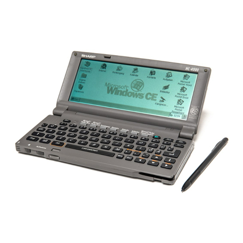
Sharp ZQ-3000 User manual

SHARP
SERVICE
MANUAL
ZQ-3000,
ZQ-3200
move.
ZQ-3050,
ZQ-3250
KEY
LAYOUT
FRI
DEC
17,1993
eGoooof/riany
HS]
UE]
ELIER
i
STANDARD
FUNCTION
ELEMENT:
FEM
LCD
PARTS
NAME:
LF7776Q
NUMERAL:
16
digits
(4
lines)
a
mpOoOooe
3
IZB
95
x
32
dot
matrix
liquid
crystal
nCinealacelaalaaleslaahtnles)
-
YG.
display
16
columns
x 4
lines
(with
6
x
AODmMOeMoOmoOSsA
31GG
8
dot
characters)
ea)
ww
oO
bea
le—
Ga)
GA
GA)
CHE)
OS
6)
OD
ZO—ANMH
<Pr-vn—o
KEY
SYSTEM:
Rubber
key
Electronic
notebook
section
CPU:
_LI35061F
(209pin-FILM)
SRAM:
*
ZQ-3000/3050
TEL
mode
Entsy
and
recall
of
names,
phone
numbers,
and
addresses
ATT7C256BFX1
SCHEDULE
mode
Entry
and
recall
of
dates,
appointment
times,
and
details
of
appointments
*
7Q-3200/3250
Automatic
day-forward
function,
schedule
alarm
function
AEIREEEETNE
ipa
Anniversary
notice
function
CALENDAR
mode
Display
of
calendars
from
January
1901
to
December
2099
Schedule
mark
function
distinguishing
between
maming
and
afterncon
appointments
Anniversary
mark
function
MEMO
mode
EXPENSE
mode
Memory
capacity
ZQ-3000/3050
92
Kbytes
(User
area:
Approx,
30
Kbytes)
SCHEDULE
mode
capacity:
Approx.
500
entries
TEL
mode
capacity:
Approx.
810
entries
MEMO
mode
capacity:
Approx.
226
entries
ZQ-3200/3250
64
Kbytes
(User
area:
Approx.
62
Kbytes)
SCHEDULE
mode
capacity:
Approx.
1040
entries
TEL
mode
capacity:
Approx.
1680
entries
MEMO
mods
capacity:
Approx.
460
entries
POWER
SUPPLY
Main
power
supply:
6
VDC
lithium
batteries
(CR2032
x
2}
Memory
backup
power:
3
VDC
lithium
battery
(CR2032
x
1)
4
o
7
o
3
a
Qa,
o
®
The
approximate
entry
capacilies
above
assume
the
following
average
entry
sizes
AC
ADAPTOR
|__
a
when
all
memory
is
used
ive
single
mode.
: ;
is
RECHARGEABLE
aa
SCHEDULE
Aeor
Mm
;
scription
32
characters/ent
BATTERY
|
TEL
ne
i
i
characterlenty
umber
aracters/en'
POWER
0.02
W
MEMO
128
characters/entry
TGPOMEH:
pe
eee
eg
AUTO
POWER
length
per
entry
OFF
TIME
Approx.
7
minutes
Secret
function,
data
transter,
index
display
MEMORY
Ven
PROTECT
Crystal
oscillation
frequency
DIMENSIONS(mm)
Open:
138(W)
x
160(D)
x
9{H)
mm.
Closed:
138(W)
x
80(D)
x
17(H)
mm.
addition,
subtraction,
multiplication,
division;
constant,
square
root,
percent,
memory
calculation,
etc.
Accessories
Lithium
batteries
(CR2032
x
3)
Operation
manual
92,768
Hz
fon
Average
variance
445
seconds
per
month
(at
25°C/77"F)
Content
of
displays
|
year,
month,
day,
day
of
week,
hours,
minutes,
A.M./P.M.
12-hour
and
24-hour
clock
a]
9)
a)
2|8
let
|
26.
3/a)e4
®
Approx.
500
hours
When
data
is
continuously
displayed
at
an
ambient
temperature
of
20°C
(68°F).
®
Approx.
380
hours
When
data
is
searched
for
5
minutes
per
hour,
and
the
data
is
displayed
for
55
minutes
per
hour,
at
an
ambient
temperature
of
20°C
(68°F).
®
When
off,
and
the
clock
is
running,
operating
lime:
Approx.
4
year
®
Memory
backup
battery
life:
Approx.
5
years
(if
operating
batteries
are
replaced promptly
when
exhausted)
Approx.
3
years
(if
operating
batteries
are
exhausted
or
not
installed)
This
document
has
been
published
to
be
used
for
after
sales
service
only.
SHAR
P
co
R
P
O
RATI
O
N
The
contents
are
subject
to
change
without
notice.

—
ae
ZQ-3250
1.
CPU
(LI35061F)
terminal
description
Fao
Presta
|
1
[Testingut
[ads
_|
©
|
Aderess
output
rtest
[1
[Testinput
[aba
|
©
[Address
output
[S16
[ste0
|
©
[strobe
ouput
[AD2
|
©
[Address
output
[S17
[sTe1_|
©
|Stobe
ouput
[AD+
|
© |
Adcress
output
[ste2
|
0
[Strobe
output
[E01
|
©
|
Output
por
Strobe
output
BZ
Buzzer
output
Strobe
output
Output
port
Strobe
output
Key
input
Strobe
output
Strobe
output
Strobe
output
Strobe
output
Strobe
output
Strobe
output
Strobe
output
Strobe
output
Strobe
output
Strobe
output
Signal
name
‘Signal
name
1s6é6
|
O |
Segment
output
Segment
outpu
'se7
|
0
|
Segment
output
Segment
output
seg.
|
0
|
Segment
ouiput
Segment
output
seg
|
O
|
Segment
output
Segment
output
Is70
|
(0
|
Segment
output
Segment
output
Is71
|
0
|
Segment
output
Segment
output
S72,
|
0
|
Segment
output
[Segment
output
[873
|
O
|
Segment
output
|
[S23
|
©
[Segment
output
[S74
_|
©
|
Segment
output
Power
source
[s24
|
©
[Segment
output
[$75
|
0
|
Segment
output
Reset
input
0
|
Segment
output
[876__|
©
|
Segment
output
|
Crystal
oscillation
output
Segment
output
|
S77
Segment
output
Crystal
oscillation
input
Segment
output
|}
S78
Segment
output
Power
source
Segment
output
|
S79
Segment
output
Crystal
oscillation
power
source
Segment
output
Segment
output
Segment
output
Segment
output
‘Segment
output
Segment
output
Segment
output
Segment
output
Segment
ouiput
Segment
output
Segment
output
Segment
output
Segment
output
Segment
output
Segment
output
Segment
output
Segment
output
Segment
output
Terminal
name
i/O
|
Terminal
name
VO
—_
—_
H
I
Wn
®
ve)
3
D 3
oe
°
i
3
=
RIS
~“
(@)
S27
1
D
QO
Power
source
LCD
drive
power
source
LCD
drive
power
source
Key
input
LCD
drive
power
source
KIS
tL
|
Key
input
V
LCD
drive
power
source
Kia.
|
1
{Keyinput
iva
|
|
LCD
drive
power
source
[Kis
__|t
[Keyinput_[H16
|
©
[Common
output
|
rki2|_1
[Keyinput____[H15
|
©
[Common
output
[S97
fit
|
1
[Keyinput__[H14_|
©
[Common
output
|
[o10_|VO[Datavo___|H13|
©
[Gammon
output
Data
I/O
Common
output
ata
/O
Common
output
Common
output
I/O
Common
cuiput
Common
output
VO
Common
output
Segment
output
Segment
output
Segment
output
Segment
output
Segment
output
Segment
output
|
S8
Segment
output
|
S88
Segment
output
Segment
output
Segment
output
Segment
output
Segment
output
Segment
output
H
OAD
A
M!|
Qin!
m|m|
a
SSS
SIS SiS
Sisi4is
C/O)
OB)
OB) cH]
co) oo)
BeBe
|B
oy)
o/h
o
;
<|<|/</</<
><
~]
oO;oO
ole
=
ea
=
ae
o/5
3/5
alo
o/s
3\3
5.
|
5.
$91
11
4
io)
wm
bibl
Ail
bl
i
i
il
—_
aa
4
a
{ta
a
3/3
3
@
|
a@
ry)
=|
2.
o;o
o
=a
UU
\|U
5
5/5
5.
g 9
=
2
ela
igiglele
BIS)
S|
h
|
s
3|5/5]/5/5
id
Mi
DIMN
OlLOAILOILOlOIO
DioDiniIiaqlialaslsd
@/6
12/3
/3/3/3/3/8
2/21/23
/3
13/3/3132
S2/2/2/8/8/Si8Sis/s
ele|elei2l2e/2/2|2
slelslelslslelsle
Sisisisislslelgls
H17
Common
output
CcE3.
|
O|
Chip
enable
output
$47
/Hi8
|
Common
output
\CE2
|
O
|
Chip
enable
output
H4
1Hi9
|
Common
output
IcEI
=|
O|
Chip
enable
output
Common
output
[RAW
|
O
|
ReadMrite
output
—_|
H21
Common
output
[BAos
|
©
|Bankaderess
output
[Ht
|BAGS
|
O
|Bankaddress
output
|Si_
|
O
|
[eao2
|
©
|
Bank
aderess
output
[52
|
0
|
faaot
|
©
[Bank
aderees
output
[53]
0
|
[ADIs
|
©
[Adcress
output
|84_|
0
|
Segmentouipat
|
[ADI
[0
[Adcress
output
__|s5_|
0
|)
|
O
|
ADI2
|
0
|
AD1i
|
O|
Common
output
Common
output
Common
output
Common
output
Common
output
Common
output
ut
re
©
~l
H2
H30
H31
H32
$97
io
“I
Common
output
a
on
©
~l
to
|
a]
a
CHO
ALMA
AI
AMADA
AM
Min alo
Oo;i@m
im
DBI
GIioni
ol;
oslo
gaignivnivniatisla
©
wm
ia
1
1
10
1O
10
1a
1
10
(oO
1a
1a
SISISISISISISIS
ISIS
ISIS ISIS
ISIS
O;@O;1oO
DIiOBIinl
Di
ODI
DO
Dianjoga
ltl
orlrola
Sleialaialelalal
si
slelea
SS
glele/elelele/2/2|/2|2/2\2/2/2\2
#|\$/18
|S 16 13 |S |S |S |S lS
18/8
le le
le
SISISISIS/EISISIBIGCICI(SIS\ZISI5
Common
output
Common
output
Segment
output
Segment
output
#
Oo
—
a
i
Segment
output
alalajalalaislale
a/ajajalajajaiala
gle
isigieisisigis
#18
18/8/1818
(8/8
|g
ojo
;o;aq;atorfo;o]o
Sigisgig/Sigisi
Sis
Sls
ls
lols
isidgigig
BIE/S/E/E/EIS/S/5
Segment
output
Mm
H|\MO
vaim|
mal
alalm
oO
Oonl
olo!l|a!|
ola!
a
m
Om
iimin
la
|e
ia
ia
SIS|SISISISIS
ISIS
(3
@
Olin
ioDiconio{i
o;|aloa
3
3/375
7/35
/;/a7;9g
|3/3
7
Fo
ol
on
ott
Ee
ae
oe
ae
eo.
elelelelelel2
lz
izle
5/515
|$/8|8
18/8
|S
/S
EIS/SlSislslsjsigis
0
|
ADs
|
O°
Abs
|
0O|
AD7
|
0|
|
|
|
0
|
Be.

2.
Regulator
(Internal
block
diagram)
3.
Detector
(Internal
block
diagram)
VDD
OUT
VSS
4.
Low
voltage
detection
method
®
In
this
model,
a
warning
is
given
only
to
the
main
battery
exhaus-
tion,
not
given
to
the
backup
battery
exhaustion.
The
main
battery
exhaustion
is
detected
in
the
circuit
shown
below:
YCC
E01
KI8
(Nch
open-dagin
type)
GND
aa
ZQ-3250
1)
Caution
level
(detection
voltage:
About
4.8
~
5.3V)
When
the
caution
level
is
detected
while
displaying,
the
low
battery
symbol
([BATT
|)
is
lighted.
When
the
caution
level
is
detected
on
supplying
the
power
to
the
set
or
on
pressing
the
reset
switch,
the
battery
replacement
indica-
tion
(PLEASE
REPLACE
THE
OPERATING
BATTERY
!)
is
dis-
played
for
about
4
sec.
When
the
caution
level
is
detected
while
sounding
the
alarm
or
key
input
sound,
the
alarm
sound
or
key
input
sound
is
stopped.
2)
Fatal
level
(Detection
voltage:
About
4.4
~
4.8V)
When
the
fatal
level
is
detected
while
displaying,
the
whole
system
is
turned
off.
When
the
fatal
level
is
detected,
on
supplying
the
power
to
the
set
or
on
pressing
the
reset
switch,
the
whole
system
is
tumed
off.
When
the
fatal
level
is
detected
while
sounding
the
alarm
sound
or
key
input
sound,
the
alarm
sound
or
key
input
sound
is
immedi-
ately
stopped.
After
100ms,
the
voltage
is
restored
and
the
next
process
is
performed.
When
the
fatal
level
is
detected
while
the
power
is
off,
pressing
the
key
will
not
supply
power
to
the
set.
The
reset
key
is
also
disabled.
(Until
the
battery
is
replaced.)
[Note]
Since
low
voltage
detection
is
not
performed
for
the
memory
protection
battery,
please
note
the
battery
replacement
label
and
replace
when
necessary.
5.
Alphabet:
Caps/Low
Caps/Low
of
alphabet
can
be
selected
by
pressing
the
[CAPS
key.
When
the
power
is
supplied
by
pressing
the
key,
Caps
ts
selected.
(Caps
symbol
is
lighted.)
@
Circuit
©
This
circuit
has
no
hysteresis
characteristics.
VCC
EOI
RESET
SW
key
®
Software
1.
Caution
level
is
detected
every
0.5sec.
(FO1
=
GND)
2
In
normal
cases,
only
the
fatal
level
is
detected.
(EO1
=
Vcc)
3.
Even
when
the
system
is
off,
the
fatal
level
is
detected.

ZQ-3250
6.Memory
map
—_
SYSTEMAREA
|
USER
AREA
0000H
0420H
,
2000H
Ill
(82KB)
4000H
6000H
_
1
(8KB)
-
7FFFH
=
8000H
|
7
(@KB)
AQO00H
CE2
CO000H
(32KB)
IV
(82KB)
EOO0H
FFFFH
*
PLA
is
selected
so
that
CE1
is
outputted
to
the
former
half
space
of
32KB
and
CE2
is
outputted
to
the
latter
half
of
32KB.
(CE1,
CE2:
The
chip
enable
output
for
addressing
the
external
memory)
*
Either
when
one
8KB
RAM
is
used
or
when
two
8KB
RAM’s
are
used,
the
former
haif
RAM
address
is
assigned
to
6000H
level.
This
allows
continuous
assignment
of
addresses
when
two
RAM’s
are
used.
RAM
capacity
aaa
eat
Memory
type
(D7H)
8KB
(I!
only)
2
16KB
{I
+
Il)
32KB
(III
only)
64KB
(Il)
+
IV)
ZQ-3000/3050
ZQ-3200/3250
(In
case
of
error)
0
7.
Conduction
test
*
Check
conduction
be-
tween
@)
and
@).
Max.
109
@)
=
Backup
battery
©
terminal
=
Electrostatic
sheet
(Plain
serface)
8.
Current
check
(VCC
=
6.0V)
1.
Press
the
OFF
key.
2.
Measure
the
current
value.
(After
1
sec.)
When
OFF:
11.3,:A
or
less
3.
Press
the
ON
key.
4.
Measure
the
current
value.
When
ON:
365z:A
or
less
9.
Note
for
Battery
replacement
Replacing
batteries
Batteries
used
in
the
Organizer.
[Woda
_[
Oy
“or20aa
[2
[Uritoperaion
The
standard
built-in
clock
is
powered
by
the
operating
batteries.
Type
Lithium
battery
Lithium
battery
Precautions
when
replacing
the
batteries.
Before
repiacing
the
battery,
be
sure
to
press
to
turn
the
power
off.
Do
not
replace
the
memory
backup
battery
when
the
operating
bat-
teries
are
depleted.
When
the
operating
batteries
become
weak
and
you
turn
the
power
on,
"EME
“
will
be
displayed
and
the
following
display
will
appear
temporarily:
Please
replace
the
operating
batteries!
BATT.
if
the
batteries
become
weaker
(the
alarm
or
the
key
beep
does
not
sound),
the
power
may
go
off
during
operation
or
the
Organizer
may
fail
to
turn
on.
The
memory
contents
will
still
be
retained
by
the
memory
backup
battery.
Replace
the
operating
batteries
to
avoid
loss
or
alteration
of
data.
Before
removing
the
batteries
for
replacement,
record
important
infor-
mation
on
paper.

10.
Using
the
data
transfer
function
This
Organizer
can
transmit
data
to
and
receive
data
from
the
follow-
ing
products.
1,
Data
transfer
between
ZQ-3000
series
Organizers
(using option
CE-200L
or
CE-300L).
2,
Data
transfer
with
a
ZQ-5000
or
IQ
series
Organizer
(using
option
CE-200L
or
CE-3O00L).
3.
Data
transfer
with
an
EL
series
Organizer
(including
Auto
Dialer)
that
has
data
transfer
capability
(using option
CE-2207).
Before
establishing
communication
between
products,
turn
the
products
off
and
connect
the
cable.
Notes:
©
To
interrupt
data
transfer,
press
©
If
a
connector
is
disconnected,
or
a
similar
problem
occurs
during
data
transfer,
the
message
"/O
DEVICE
ERROR’
wilt
appear.
*
After
data
transfer,
the
data
on
the
transmitter
is
preserved.
10-1.
Transferring
data
between
ZQ-3000
series
Organizers
Telephone
directory data,
schedule
data,
and
memo
data
can
be
transferred.
Data
can
be
transferred
and
verified
by
mode
{all
items
in
the
SCHEDULE
mode,
MEMO
mode,
or
a
telephone
directory
—
TEL,
TEL2,
TEL3)
or
by
data
item.
In
addition,
data
can
be
backed
up
using
Organizers
of
the
same
type.
Transferring
data
by
mode
and
by
data
item
Schedule
data
are
transferred
by
mode.
During
mode
transfer,
data
previously
stored
in
the
specified
mode
of
the
receiver
are
deleted.
Proceed
with
a
caution.
Note:
When
mode
transfer
is
carried
out
in
the
telephone
directory
mode,
all
listings
in
the
directory
will
be
transferred.
(In
this
case,
the
directory
name
is
transferred
at
the
same
time.)
4.
Select
the
mode
on
the
transmitter
and
receiver.
SCHEDULE
(Transmitter)
SCHEDULE]
(Receiver)
2.
Select
the
data
transfer
function
on
the
receiver.
UNIT
TO
UNIT
SEND
RECEIVE
VERIFY
3,
Select
the
receiver
in
the
receive
mode.
2
UNIT
TO
UNIT
RECEIVING
MODE
|
4.
Select
the
data
transfer
function
on
ihe
transmitter.
UNIT
TO
UNIT
SEND
RECEIVE
VERIFY
Note:
When
transferring
by
data
item,
display
the
desired
data
and
press[2nd]
[OPTION
].
ES
ZQ-3250
5,
Perform
data
transfer.
|
Notes:
®
|f
the
mode
of
the
transmitter
and
the
mode
of
the
receiver
are
not
the
same,
data
transfer
is
not
established.
The
message
“DATA
ERROR"*
is
displayed.
When
telephone
directory
data
are
transferred,
directories
on
the
transmitter
and
receiver
can
be
different.
However,
the
contents
received
by
the
receiver
will
be
stored
in
the
open
directory.
For
example,
if
data
transfer
is
established
between
file
TEL1
in
the
transmitter
and
file
TELS
in
the
receiver,
then
the
contents
of
TEL1
will
be
sent
to
and
stored
in
TELS.
*®
Tur
off
the
secret
function
on
both
the
transmitter
and
the
receiver
before
mode
transfer.
®
If
the
amount
of
memory
available
on
the
receiver
at
the
time
of
transfer
is
insufficient,
data
transfer
is
not
possible.
The
message
“MEMORY
FULL"
appears.
Delete
any
unnecessary
data,
verify
whether
the
available
memory
is
sufficient,
and
repeat
the
data
transfer
procedure.
Transferring
backup
data
All
the
contents
of
the
Organizer
are
transferred.
During
backup
data
transfer,
data
stored
on
the
receiver
are
deleted.
Proceed
with
cau-
tion.
(Backup
data
transfer
is
only
possible
between
identical
products.)
1.
Select
the
data
transfer
function
on
the
receiver
and
set
it
in
the
receive
mode
for
backup
data
transfer.
2
,
UNIT
TO
UNIT
BACKUP
RECEIVING
MODE
2.
Select
the
data
transfer
function
on
the
transmitter
and
perform
backup
data
transfer.
1Y
Verifying
data
It
is
possible
to
verify
data
by
mode
or
by
data
item.
If
any
discrepan-
cies
are
found,
the
message
“VERIFY
ERROR"
is
displayed.
Verify
data
in
the
SCHEDULE
mode.
1.
Select
the
mode
on
the
transmitter
and
the
receiver.
SCHEDULE
(Transmitter)
SCHEDULE]
(Receiver)
2.
Set
the
receiver
in
the
verify
mode.
OPTION]
3
UNIT
TO
UNIT
-VERIFYING-
3.
Select
the
data
transfer
function
on
the
transmitter.
Note:
To
verify
one
data
item,
display
the
data
item
to
be
verified
and
press
[2nd]
[OPTION]
-
4.
Perform
verification.
1

ZQ-3250
10-2.
Transferring
data
witha
20-5000
or
IQ
series
Organizer
Telephone
directory
data,
schedule
data,
and
memo
data
can
be
transferred.
Data
can
be
transferred
and
verified
by.
mode
and
by
data
item:
Note:
When.
mode
transfer
is
carried
out
in
the
fesicna:
direcotry
_
mode,
all
listings..in
the
directory
will
be
transferred.
(In.
this
speeey
the
directory
t
name
is
transferred:
at
‘the
same
ime.
)
Transferring
data
by
mode
and
by
data
iter.
Transfer
the
“ABC
BANK*
memo
data
stored
i
in
the
Organizer.
1.
=
the
data
in
the
transmitter
to
be
transferred.
re
To
perform
mode
transfer,
selact
the
mode
by
pressing
‘the
“mode
key,
and
then
press.
It
is
not
necoseaty,
to
~
display
the
data.
ay
ee
2.
Select
the
data
transter
function
on
|
the
receiver,
and
set
the
receiver
in
the
receive
mode.
;
;
3.
‘Select
the
data
transfer:
Meictien:
on
the
transmitter
schea
d-pertorm
‘data
transfer.
©
ieee
[2nd]
[OPTION]
1
_
Note:
Follow
the
same
steps
to
transfer
data
from
a
Za.
5000
or
1a
series
Organizer.
Verification
Follow
the
steps
explained
in
"Transferring
data
between
ZQ-3000
series
Organizers"
above.
10-3.
Transferring
data
with
an
EL
series
Organizer
(including
Auto
Dialer)
Telephone
directory
data
and
schedule
data
can
be
transferred:
(For
the
Auto
Dialer
only
the
telephone
direcory
data
can
be
transferred.)
Data
can
be
transferred
by
mode
and
by
data
item.
When
transferring
data
with
an
EL
series
Organizer,
the
following
restrictions
apply:
*
When
transferring
data
to
an
EL
series
Organizer:
Transferred
data
are
added
to
the
data
previously
stored.
Data
are
transferred
in
the
same
mode
and
directory.
lf
the
transferred
data
item
exceeds
the
maximum
number
of
char-
acters
that
can
be
entered
into
the
El.
series
Organizer
as
one
data
item,
excess
characters
are
deleted.
Characters
and
symbols
that
cannot
be
displayed
on
the
EL
series
Organizer
are
replaced
by
spaces.
If
all
the
columns
that
can
be:
displayed
are
replaced
by
spaces,
the
correspanding
data
item
is
not
stored.
All
received
letters
are
converted
to
capital
letiers.
If
the
secret
function
is
turned
on
in
the
Organizer,
only
non-secret
data
are
trarisféerred.
*
When
transferring
data
from
an
EL
series
Organizer:
The
received
data
are
added
to
the
data
previously
stored.
When
receiving.
non-English
characters,
all
characters
are
con-
verted
to
small
letters.
If
the
secret
function
is
turned
on
in
the
EL
series
Organizer,
only
non-secreit
data
are
transferred.
Transferring
data
to-an
EL
series
Organizer.
.
ni
Transfer
all
TEL1
data
ii
the
‘Organizer
to
TEL!
in
the
EL
Séjiés
Organizer.
.
. .
1.
Set
thé
recéiver
in
the
receive
mode.
2.
Select
the
made
on
the
transmitter.
_
TEL
|
Since
telephone
directory
data
is
being
transferred,
‘select
the
file.
3.
Select
the
data
transfer
function
on
the
transmitter.
‘(nal
[OPTION]
Note:
To
transfer
one
data
item,
disp
la
the
data
iter
to
be
traris-
ferred
and
press
[2nd]
ran
4.
Perform
data
transfer.
*
|f
the
arnount
of
memory
available
in:
‘the.
receiver
at
the
time
of
data
transfer
is‘
insufficient;
an
error
message
appears.
Delete
any
unnecessary
data,
verify
that
there
is
sufficient
memory
available,
and
Tapeat
the
Process.
Transferring
data
from’:
an
EL
series
Organizer
1.
Select
the
mode
on
the
receiver.
2.
Select
the
data
transfer
function.on
the
receiver,
and:
set
the
receiver
in
the
receive
mode.
3.
Perform
data
transfer
from
thet
transmitter.
;
11.
When
trouble:
7
An
impact
or
a
strong
exieral
electrical
field
may
iseve
none
Ma
the
keys
operational.
Press
the
RESET
switch
on
the
back
of
the
Or-
ganizer.
The
impact
or
external
eects
field
may
erase
some
or
all
of
ithe
Organizer’s
memory.
-
Press
the
RESET
switch
with
the
tip
of
a
ball-point
pen
or
similar
object,
but
not
anything
breakable
(like
a
pencil
point
or
a
needle).
All
RESET
operation
If
a
problem
occurs
after
replacing
the
batteries,
or
if
the
Organizer
does
not
function
properly
even
after
the
above
RESET
operation,
perform
the
following:
1.
While
holding
[ON],
press
the
RESET
switch
on
the
back.
Release
the
RESET
switch
and
then
release
[ON].
The
following
display
will
appear.
DATA
ALL
CLEAR
2.
Press
[_N_]
Returns
to
the
initial
display.
Caution:
Do
not
press
Lyi
in
step
2.
Pressing
[¥..
LY¥._]
wil
~"
deléte
all-data
and
teset
the
clock.’
.

12.
Contrast
adjustment
Adiust
the
display
contrast
to
make
the
display
easier
to
read.
1.
Press
[FUNCTION].
<
FUNCTION
>
MEMORY
CHK
i
LcD
DATA
DEL
NO
2.
Select
“2
LCD
CONT".
2
LCD
CONT
v
—
DARK
A
—
LIGHT
3.
Press
[a]
or
['¥]
to
darken
or
lighten
the
display
as
required.
The
amount
of
contrast
will
change
continuously
when
either
[a]
or
[¥]
is
held.
4,
After
adjusting
the
contrast,
press
;
13.
Turning
the
"beep"
on
and
off
While
"»"
is
displayed,
a
beep“
will
sound
when
a
key
is
pressed.
To
turn
the
"beep"
on
and
off,
press
.
The
“beep”
will
not
sound
after
"}"
goes
off.
To
tum
the
“beep”
back
on,
repeat
the
process.
14.
Difference
between
the
ZQ-3000
series
®
Display
film
calendar
@®)
type
(The
left
end
is
Sunday.)
SUN
MON
TUE
WED
THU
_FRI_SAT
ZQ-3000,3200
type
(The
left
end
is
Monday.)
MON
TUE
WED
THU
FAI
SAT
SUN
Z2Q-3050,3250
a
ZQ-3250

ZQ-3250
15.
Diag
function
check
nt)
2?
Operation
onteriti
25"
Initial
setting
1
ae
eal
|
DATA
ye
POLPAILL
|CLEAR
Press
key.
Initializing
diag
When
pressing
and
[D}
keys,
press
RESET
TAG
function
3
a
switch.
Function
selection
and
Press
[4].
aa
_
).
Check
the
display
for
display
check
Press
[ENTER].
defects;
blurs,
leaks;
Press
[ENTER|.
Ab
apdother
ow.
abnormalities.
Press
|
ENTER].
Press
[ENTER].
(Note
1)
oe
Ade
Key
check
Key
input
check
Press
all
the
keys
(79
keys)
except
for
[ENTER]
kéy.
|
KEY
CHK
OK
Key
check
end
Press
[ENTER]
key.
Must
be
"OK."
(Note
2)
RAM
check
Press
[ENTER]
key.
TKEY
CHK
OK]
|
Mustbe
"OK."
(Note
3)
(Automatic
check)
Check
time:
ZQ-3200/3250
—
About
30sec
RAM
32K
OK
Bk
to
ce
2Q-3000/3050
—>
About
17sec
arm
2Q-3200,
3250
-
2k
|
ZQ-3000,
3050
>
32K
Communication
check
is,
se
8
Connect
the
set
(@)
(mother
unit).
Set
the
mother
unit
to
the
check
mode.
>
Press
{>
(Mother
unit
display)
4PIN
CHK
Set
A)
(mother
unit)
Press
[ENTER
|
key.
(Automatic
check)
|
Must
be
"OK."
Remove
the
set
@).
(Disconnect
the
4-pin
connector.)
Press
|ENTER]
key.
Diag
end
Contrast
check
Function
selection
Press
and
keys.
Enter
[2].
Keep
pressing
key
for
about
3
sec.
Keep
pressing
key
for
about
3
sec.
V-LIGHT
Calendar
check
Pattern
E
(Perform
prior
to
contrast
check.)
Check
that
January
1,
94
is
"SAT."
Press
{CALENDAR
|
key.

PatternA
Pattern
B
4
BATT
30:31:
EDIT
sHtFT
[A]
caps
x[s]
<9
t
Pattern
C
:
Pattern
D
(All
symbols
are
lighted.)
Pattern
E
SUN
MON
TUE
WED
THU_FRI
SAT
MON
TUE
WED
THU
FAI
SAT
SUN
ZQ-3000,3200
ZQ-3050,3250
Note
1:
When
pressed
2
times
or
more,
"KEY
CHK
NG"
is
displayed
and
operation
is
stopped.
Note
2:
When
check
program
is
stopped
by
mis-operation,
press
and
[C/CE]
keys
to
reset
to
state
"2."
Note
3:
When
check
program
is
stopped
by
mis-operation,
press
and
[C/CE]
keys
to
reset
to
state
"2."
ZQ-3250

ZQ-3250
16.
Note
for
servicing
™
Remove
the
battery
cover.
9)
Remove
battery
protect
B
55.
(Note)
-
There
is-a
screw
beneath
battery
protect
B.
When
remov-
_
ing
the
keyboard
lower
cabinet,
battery
protect
B
must
be
removed.
|
1)
Loosen
screw
59.
(QJKODO00004M
eg
eee
oe
) (
N
m@
Remove
the
keyboard
lower
cabinet.
2)
Remove
battery
cover
58.
a
Se
hes
(Note)
Screw
59
is
so
constructed
as
not
to
be
removed
for
prevention
against
missing.
@
Remove
the
battery.
10)
Remove
the
screws.
(7
pes.)
(0JKOD000100M/)
44)
Remove
the’screw.
(1
pe:)
(7
pes.)
(OJKOD000100M/:
3)
Slide
battery
replacement
switch
48
to
"REPLACEM
ENT"
side.
4)
Slide
battery
protect
B
55.
5)
Remove
the
battery.
(MAIN
side)
61
?
f"
7)
l"
53
12)
Remove
the
keyboard
lower
cabinet
49
from
the
hinge
side.
6)
Remove
caution
label
61.
13)
Remove
push
knob
50,
7)
Remove
the
screw.
(0JKOD000100M/)
8)
Remove
battery
protect
A
53,
and
remove
the
battery.
(Backup
side)
=ii=

ZQ-3250
m
Remove
the
PCB.
m@
Remove
the
key
sheet.
14)
Remove
the
screw
and
remove
pressure
plate
33.
22)
Remove
the
screws.
(4
pcs.)
(QJKODO001
OOM/)
(QJKOD000101M/)
23)
Remove
ALM
sheet
6.
15)
Remove
the
screw
and
remove
collar
20.
(OJKODO00101
M/)
24)
Remove
key
sheet
5
416)
Remove
the
knob
conductor.
17)
Remove
the
PCB.
m@
Remove
the
hinge.
18)
Remove
electrolytic
sheet
27
under
the
PCB
and
remove
rubber
key
B
29.
@
Remove
the
lower
cabinet
in
the
LCD
side.
20)
=
~
25)
Remove
hinge
overlay
22.
(Note)
The
hinge
overlay
is
attached
with
duplex
tape.
26)
Remove
the
screws.
(3
pcs.)
(QJKOD000103M/)
19)
Remove
DIS
overlay
1.
)
Remove
overlay
27)
Remove
hinge
B.
(Note)
The
decoration
panel
is
attached
with
duplex
tape.
20)
Remove
screws.
(3
pcs.)
(0JKOD000100M/)
(Note)
There
is
no
screw
beneath
the
10
key
panel.
21)
21)
21)
Remove
DIS
lower
cabinet
7
from
the
hinge
side.
414

ZQ-3250
AyUp
Volsia,
ayAgypo
pyy
ie
iL
1:
cross
391
a
=
(07
=
s
a
a
=
Ln
>
2
=
ae
1:
an
i
=
|
eeoza
|
axzeoraa
|
-
oH
:
|
=
~
=
Jd
op
Uden
o
-
7
]
nM
;
+}
a
ait
=
a
ea
ORT
|
—
:
ht}
—
Thiaypdg
dnyoeg
PH
Ng
=
|}:
|feFR
&
4
EF
a
i
e
es
take
>}
Ppa
We)
148
Ea
-
cee
Ol
fi
PR
rae
?
TiC
E
:
.
afuryy
disyyeg
orl}
:
1oyoennog
nalydg
:
a
smiiUieninat
Ere
rrereerr
TLE
Perrier
reer
eA
Pr
1]
CUIALAG
GDIZWON/NdD)
4190SE17
ioyaeunag
[ees jeay
O9LL241
007
NIS4
-lelepi<
FEEEErEr
—
o3
=
ae]
—
ae
=
-|
=|
|
l=
12
OWS
Ea
Aas
ene
uo!
;erodiog
gyyHS
epen'}
:
Ul4
OL/P
7666
FIV
araTtiy——
Fa
me
dNOX9
SHFISAS
NOLLVHYONI
:
:
NOHSIAIG
INIHdI
N03
T¥NOSYd
Reeletbal
alNg
|
INSA1U¥d30
ONIYZIN1
ONS
;noAey]
Lindiiyg
709
weibeig
WNdUID
*Z1
19s

ZQ-3250
F190
1
juewobue.e
sjeubis
sued
gid
"SL
—9=

ZQ-3250
a
=
—
I)
jr
—
—
=]
oo
SOMO
|o
oO
a
S
Lo
|
a
SLnlojio
2)
OQ
i=)
oIN
DIOININ
ul
onl
ra)
mony
691]
cn]
op
a
a
als
rye
ty
s
s
CS
olo
HOH
O
apd
oo
si
a|n
SINININ
I}
COO
[Z
[Z
DESCRIPTION
uide
late
connect
&
cabinet
nob
connector
attery
connect
©
ubber
key
B
protect
B
protect
A
ation
sheet
su
atter
sheet
sulation
sheet(Nut
nge
overia
nge
overla
inge
overla
splay
bottom
cabinet
splay
bottom
cabinet
ubber
key
A
lum
nge
overla
Display
overla
H
H
H
H
ey
top
ressure
rubber
ressure
ressure
p
atie
n
Reset
ke
hield(Reset
onductor
atter
attery
exchange
label
attery
door
nsulation
sheet
Cushion
spacer
Battery
label
Caution
label
Spacer
oO
A
bx
i
a
le
Ze
|YOQO}aO|foloiolofaloaleo
YOO/O/Qofo/q/olojajolojofojofajojololololulalea
oo
:
f
J.
use
OZ
HEF
Fos
[ojala
/olaja}aiei-|-
eS
Q]D}e9|
><]
feg]
Z|)
uasfee
|]
fuss]
ec)
wrfe>|
sf]
cofus.|
ut
for
fera|
ut]
feof
ee
O}u|miclo]olo
OE
fet
etl
at|ae
|<]
tle]
ct]
}
cc]
ex]
ec
Lief
pe]
ket
|
keep
fet
fee]
ec]
ex]
ct
eee
ex]
ec
fee
e|
te]
x]
ee|
et
ec
ec]
cfc
|e
<t)
et]
t/t
lec]
|x
Buzzer
tape
Key
bottom
cabinet
attery
exchange
day
label
.
NVNINIIINIANAATNAIAIAINININIATAIAIAAAIAIASAIAINY
\IYNININININININTINIAISEATAINIAIAAINIARAINIAARIAIARAIAAAAINIAAA,
1)
=/=/2|2|=/=/=|2|2|=|S|S/S|=/S|E/F/S/E/S/S|=/=|=/S|S|E|F|E|=/S/=S
|S
SE
NSISNNFlslSlE
SN
SlSlzisisizislsisisisisisisisls
ul
POPES
|
PSE
SFL
HL]
4]
Oy
|
9]
>]
melee}
|cmf
9]
40
oy]
a]
eo] ca]
ors]
ec9
|
79]
|
ee]
fea]
teu]
eo]
co]
10
|
ew)
<r]
a]
co] eal
wolea|m
fwolen|eafet|ofe|
olosterlecloten|enlerlen
o
S
salarhelolelalololotel
cholo
le
lel
aeteeteie}eteelete|ete|ele|e|eiejclelelalo}olofola|olololajalalolololololololalolalolo
oO
elated
loos
ele
ee
SP
SI]
eI
LS
Mle
ees
[rsh
of
[of
c0|
10)
<t
ft)
seo}
ea]
<r]
ma]
|
afojun|oliofs
||
]oo|ia|
efi]
<e[lojofos}e|¢|eojeo
©]
|S]
APS]
901
2
|
28/1]
Oj
00
09]
ca}
Jeu
euleN/
eM] co} 00}
>]
20]
cute]
00]
>]
S}>
|
ew]
60]
on]
o]>]/
9]
cof
4-4]
ofa
|ca]co/eafoul
ol
esfealin|coleal
eulerleafosl
unten
‘Ss
(42)
SOS
SSE
SES]
SfE
lS
e]el
ele
|e]
elelolala|olololalololo|a|alofalolalalajalw|wmlolololololwlolo|alofolalalalololololol|alalo
uw)
3
ee
Sef
E
ISI
SFe
tele
Fiele|ele|elele[e]e|ejolololofolajololojajajo}e|ololeal-|olololalo|-lolalolololololololololololololo
©)
Som
<
Ff
D
DY
DRE
NOLEN
St
ON
et
ema
ON
rt
st
0
09}
2.0/0)
et]
st
fens]
er
fx)
co
|<
eufoufen|
tol
<t|eu|col
ou)
<r
eo]
<r
Ofrol
cu]
seco
|e]
et
fiw]
oulea|eulen
fell
eo|woleo
lial
unleo
7)
Oo
a
wl
elclotelel
cholerae
eieeiezyeleteyeisieleteteteleyelejelele|slelo|ojolojololofoja|ojololo|alololo|o/olololofolalalolo
c
h_
SEPA
|SE
fSC
SC
|
AE]
SC
Pn
|e je
|
Ee
|
nt
S| nf
nF
|
ne
ee
|
Net
Pn
fe
|r|
ae
|
|e
P|
ft
|
ee
||
neh
ne
|
sc
|
se
we
er
ee
|
ween
|e
|e
|
se
se
|
se
seeds
sexe
Ise
leeds
ele
ely
@o
OP
PFPFIPAAAPPPAEIAPI
AAP
AIPA]
A]
3]
4]
[9]
9]
9]
5[
3]
[5]
9]
15/5]
3[[5)5]5]5/5)5)/5)5)5/5/S/S56/SI5/5I/6/SI5/5
ISIS
/5
w
®
SHIPS
ISPS
ISS
Piel
elele|ele|o|e|e|ofolololojalojolojolo|alololalolalololololojclalolololololofololotololololoicle
Ow
llolela|
=
[alsls
slslalela
alsislalslals(sialsialsisisle
$ 3 5
@
be
O
=44>

ZQ-3250
)
\
DY
¢
ASO)
Y
)
\O)
by
/
Exteriors
x
mY
p
if
f
“A
iy
HW
if
49
51
CCP00009
50
+~15-

LN
IL
[2]
Packing
material
&
Accessories
Stsleastaisistals
Sj
a]
&/
2)
Ee]
SS/3)
s/s
i
9)-2)
Gf
cl
SE]
aloe
a
eS
ecle|eleclajzic
0}
og
ES
S|
GOES
—
i
3
FRO
SI}
S|SIS|
BNL
Be
Er
oe
o.
oa
Mi].
a3
1o|=|
SIS
38
VS)
Blolss19]
[sla
las
|
Ww
.
SSlSISlmlolat
lolo
SISIBISISIN|
IOIN
o
oS
fae}
wo
mSiohal?
1
(Sia
S)~o
iar)
J
C
laNion’
ho
bis
DESCRIPTION
yO}
Of
wi)
iw
a4
ed
ed
ed
Gj
S|
oO]
a}
o
S|
Of
co]
S/o
®
OF]
2.0]
w
ele}
cjeye
§
9}.9],9).
9/.o
BID)
Oy
B/D
c
3]
3)
a)
3/5
=
B/S)
SIS]
5
=
|
ta]
ta]
th]
Yo
ele}c}
cic
o
PARTS
CODE
I
INIDAAIAIAIAIARAY
Ee
|
oe
|
|
|
ae]
|
| |
|
Ofrafoleeulsr|
|e
lo]
<i
|Bolo/elalolojclojola
BS]
hs
00/45)
colo!
|
40]
ca
00]
00
et
st
eric
|
tle
lt
|
tle
Fo
Famed
Kae]
Can]
od
Kod
Fee
Coed
Col
ee
a\olofolelolololololo
19]
acy
|
2d]
or
|
ocr
ues]
rs
|
ex]
era]
ura
i
H[opo|SGfolslololaljalea
a
ad
nd
nd
ad
Bad
Baad
bap
ad
Bed
Se
HaIAP
Sa
Sa
oi
Bolo
salelolalololalo
vailable
list
oH
<x
ran)
,
<
‘
ee
Lid
yee
|
=
if
‘
=
O7|x<|x
<[o/ojo.
BIOs
.
;
oe
|<<
LC}
Ot]
xt)
<x
bes
Ns
sIma
MIO
=o
Lujuy
i
2
a
sto
oa
ma
:
win
oo
|<
:
“WO
"
ole
-16-

CAUTION
FOR
BATTERY
REPLACEMENT
{Danish}
ADVARSEL
!
Lithiumbatteri
—
Eksplosionsfare
ved
fejlagtig
handtering.
Udskiftning
ma
kun
ske
med
batteri
af
samme
fabrikai
og
type.
Levér
det
brugte
batteri
tilbage
til
leverandoren.
(English)
Caution
!
Danger
of
explosion
if
battery
is
incorrectly
replaced.
Replace
only
with
the
same
or
equivaient
type
recommended
by
the
equipment
manufacturer.
Discard
used
batteries
according
to
manufacturer's
instructions.
(Finnish)
VAROITUS
Paristo
voi
rajahtaa,
jos
se
on
virheellisesti
asennettu.
Vaihda
paristo
ainoastaan
laitevaimistajan
suosittelemaan
lyyppiin.
Havita
kaytetty
paristo
valmistajan
ohjeiden
mukaisesti.
(French)
ATTENTION
ll
y
a
danger
d’explosion
s’
i!
y
a
remplacement
incorrect
de
la
batterie.
Remplacer
uniquement
avec
une
batterie
du
méme
type
ou
d’un
type
recommande
par
le
constructeur.
Mettre
au
rébut
jes
batteries
usagées
conformément
aux
instructions
du
fabricant.
(Swedish)
VARNING
&xplosionsfare
vid
felaktigt
batteribyte.
Anvand
samma
batterityp
eller
en
ekvivalent
typ
som
rekommenderas
av
apparattillverkaren.
Kassera
anvant
batteri
enligt
fabrikantens
instruktion.
ZQ-3250

ZQ-3250
COPYRIGHT
©
1993
BY
SHARP
CORPORATION
All
rights
reserved.
Printed
in
Japan.
No
part
of
this
publication
may
be
reproduced,
stored
in.a
retrieval
system,
or
transmitted,
in
any
from
or
by
any
means,
electronic,
mechanical,
photocopying,
recording,
or
otherwise,
without
prior
written
permission
of
the
publisher.
SHARP
CORPORATION
information
Systems
Group
Quality
&
Reliability
Control
Center
Yamatokoriyama,
Nara
639-11,
Japan
1993
July
Printed
in
Japan
©
This manual suits for next models
3
Table of contents
Other Sharp Desktop manuals

Sharp
Sharp PN-L602B Instruction Manual

Sharp
Sharp Shuttle PN-SPCi5W7 User manual

Sharp
Sharp PC-AX40 User manual

Sharp
Sharp PC-4741 User manual

Sharp
Sharp MZ-3500 User manual

Sharp
Sharp MZ-700 Series Installation guide

Sharp
Sharp YO-250M User manual

Sharp
Sharp PC-6220 User manual

Sharp
Sharp PC-4741 User manual

Sharp
Sharp MZ-80A User manual

Sharp
Sharp MZ-700 Series User manual

Sharp
Sharp MZ-80B User manual

Sharp
Sharp MZ-808 User manual

Sharp
Sharp MZ-800 User manual

Sharp
Sharp SCR3042FB User manual

Sharp
Sharp MZ-3500 Instruction manual

Sharp
Sharp MZ-80B Installation guide

Sharp
Sharp MZ-5600 User manual

Sharp
Sharp ZQ-4450M User manual

Sharp
Sharp PN-TPC1W User manual