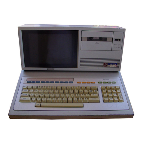
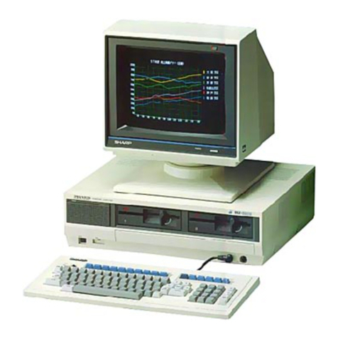
Sharp MZ-5500 User manual

MZ-5500/5600
TECllNICAL REFERENCE
Vol.2
(HARDWARE)
SlIARP CORPORATION

TABLE
OF
CONTENTS
S~ction
One
System
'
Specifications
1.
Introduction
--------
-
----------------------
----
-------------
--
--
----
--------
-
1
-1.
MZ
-
5500
series
hardware
description
-----
-----
--
--
-
---
--------
--------
-
------
2
1
-2.
MZ
-
5600
series
hardware
description
---
--
---
-
---r---------------------
-------
3
1
-3.
MZ-5500
specification
-----~----
~-
---------------
---
---
-
---------
-
----
-
-
-
----
~
1
-4.
MZ-5600
specification
--------
-
--
---
---------------
--
--------------
---
-------
b
1
-5.
Optional
devices
specificationß
(for
MZ
-
5500/5600)
------
-~
--
---
---------
----
g
1
-6.
Optional
devices
specifications
(for
MZ-5500)
----------------------
--
------
-
/0
1
-7.
Optional
devices
specificatio~s
(for
MZ-5600)
----
-
---
-
-------------
--
-------
10
,

Section
Two
Hardware
Specifications
I.
C
PU
pe
ripheral
------
--
--------
--
--------
--
---------
--
--------
--
-----
---------/2
2.
M(
'
mory
- -
--
-------------------------------------------------------------------
~
2- 1•
~lZ-5500/5600
memory
and
memory map
-----
--
------
-
------------
--
--------------
,q
?
-2
.
1/0
map
---
-----
--
-----------------------------------------------------------
2\
L
IllterrtJpt
circuit
---
----
-
----------
----
----------------------------
-.:....
--
-----
-
'21.:>
~
- 1 •
Inlrrrupt
circuit
------------------------------------------------------
-----;2b
~
- 2 .
lI~nclling
of
user
interrupt
-
---
----
--
---------
-
------------
-
------
-----
------27
3- J . SysLem
interrupt
(IR-2S)
specification
--------------------------------------30
I, •
Software
timer
-----------
-
---------------------------------------------------34
') .
Expansion
slot
----
------
-----
--
------------~---------------------------------31
MZ-5500/5600
e
xpansion
slot
(HZ-IUOS)
---------------------------------------37
r
,.,
)-
L.
.
Expnnsion
signal
description
(common
for
the
HZ-SSOO
and
HZ-S600)
---
--------38
)-
3.
1/
0
address
setup
-
--
--
--------
--
--------
---
----------------~-
--
-----
------
--3q
) -
4.
1/0
slot
timings
-------
-
----------------------------------------------
------1-0
r)
_
')
•
1/
0
port
interfacing
examples
(user's
job)
-
--
------
-----
-----
-----
---------
-4
~
()
.
UMA
--
0-
-----
------
-
-----------------------------------------------------------43
()
- 1 • m1t\ C on t
ro
L wi t h
HZ
-
5500/
S600
-
--
--------------------------------------------4-3
()
- 2 .
Op
r r;l t iolla 1 t
heo
r y
- -
--------------~------
--
---------
--
-------
- -
---
-----
-----er
3
ho, 3. lis
t"
of
mlt\
channeL
J
------
--
-
---
---
--------
------
--
-
--
----------
-
-----
------
4(,
7. Milli -
floppy
disk
interface
----
--------
---
-----
--
-----------------------------50
7- I •
(
~e
n e
ral
descr
iption
(MZ
-
5500)
----
-----
-----
--~
-
---
------
-----
-----
--
--------5o
7- 2 •
~l
l-56
00
~lFD
(640Kß)
interface
general
description
(HZ-S600)
----
-------
------52.
R.
11
;n
cl
dis
kin
t e r
fa
ce
gen
e r a L
des
c r i pt
ion
- - - - - - - - - - - - - - - - - - - - - - - - - - - - - - - - - - - - - - 55
<).
Print
e r
interface
----
-
----------------------------~----
~
---------------------~-g
9-
I .
Circ
lIit
description
-----------------------~-------------------------------
-
-~
9
-2
.
lI<1ndling
printer
control
code
(function
code)
--
-
----------
-
--
-
---------
-
----60
9-.3 . M<1king a
hard
copy
of
tlle
video
screen
--
-------
----
------
-----
------
-----
---60
10.
RS
2J2C
interface
---
-----
-------
--------
-
----------------------------~-
-------bl
1() - I • Sp
ec
ification
----------------------------------------------~------
-
---------6\
10
-2
.
Input/output
si~nals
and
control
signals
------------------------------------62
lO-
J.
P
ro
ce S s ou t 1i
ne
-------------
--
------
-
---------------------------------------
64-
10
- 4 .
Wiring
e
xample
------
-----
--
-
--
-----
--
---------------------------------------66
I
()
-5. RS2J2C
sample
program
----
-------
----
-----
--------
-----
------
-
-
--
------
------6
~
1
I.
Kp
ybo
ard
and
k
eyboard
interface
---
-
--------~--.:....-----------------
-
-------
-
--
--
ryo
11-
I.
K
ey
hoard
specifications
-
--
--------------------------------------------------~0
I 1- 2 . K
ey
board
interface
--
--~
-------------------------------------------------
----~o
I
1-
°3. Kpy
searcll
timing
-------
---
--------
--
----~-
-----
-------
-
--------------
-
-----q2
1 1- 4 .
Eig
llt
-bit
keyboard
processo
pP080C49
--~-------------------------------
-
----q2
r
12 .
MOli
se
(~lZ-
IX10)
----------------------------------------------------
------
----
rr:\-
1
2-
1.
()pprating
principle
--
-----
----------------
-
--
--
-----------------------------~4
13.
R-rc
(Real
Time
Clock)
-------------------------
--
-----------------------------~~
11-
1.
Operational
description
-
~
----
--
-
---
--------------------
---
--------
--
--------~1
13-2.
Acce
ssing
the
RTC
internal
RAH
-----
---------
--
---------
---
--------
--
------
--
82
14.
PCG
(p
rogr
ammab
le
Sound
Gene
ra
tor)
---
-------
---------
--
--------
--
---------
--
-
').}
~
15.
Vid
e o
display
circuit
--------------------------------------------------------~6
15-
I.
Fe
<1
t
ure
s 0 f t he v i
deo
dis
p1ay
ci
rc
u i t
-----
-
--
---
------
----
------
-----
-----
--
&b
1')
-
2.
IIS
p.
of
video
display
circuit
(software
control)
--
------
--------
---
----------
W
1
6.
Pov.1P r SlIpp Iy un i t
----
--
----------------------
-
------------
-.:
-
--
-----
------
----
10(,
1,
7.
80H7
CO
f)[oceSSor
option
-
-------
--
-
--
---------------------
--
-----
--------
-----
toS
SECTION
ONE
System
Specifications
1.
Introduction
The MZ-ssOO
series
is
the
first
16-bit
MZ
series
persona)
computer
in
which
the
Intel's
8086
is
used
for
the
CPU.
It
has
been
designed
\·
.dth
intense
care
for
man-machine
interface:
th
e
mOllSt
~
,
the
bit
map
display
system,
and
the
multiwindow
display
function
are
introduced
to
the
MZ-5500
series.
It
has
the
system
RAM
area
of
128KB (MZ-5511)
ur
256KB
(HZ-5521)
as
standard
and
:i.
t
can
also
be
expanded
to
sl
,
2KB
at
a
max
imum.
The
96KB
video
RAM
area
1s
provided
standard
and
it
also
can
be
expanded
to
192KB,
permitting
clear
color
graphie
displaying.
Up
to
two
units
of
320KB
(formatted)
mini-floppy
disk
drives
can
be
internally
installed,
and
the
OS
(Operating
System)
is
contained
in
the
5.25"
disk
media.
The
OS
supports
CP/M-86
and
MS-DOS
as
option.
Not
only
the
MZ~s600
series
succeeds
all
functions
and
features
from
the
MZ-5500
series,
but,
it
also
permits
the
following
external
me~ory
expansion
and
higher
processing
speed.
1)
8MHz/5MHz
selective
for
operation
of
the
8086-11
epu.
2)
Implementation
of
the
640KB
(form~tted),
5.25
11
floppy
disk
drive.
3)
Use
of
the
10.7MB
(formatted),
5.25"
hard
disk
(MZ-s64s).
Not
only
the
MZ-s645
has
one
unit
of
the
internal
llard
disk
drive,
it
also
enhances
expansion
to
21.4MB when
the
MZ-IF18
external
hard
disk
drive
is
added
(applicable
'
for
the
200V
version
only).
The MZ-S600
enables
absorption
of
the
software
cre~ted
on
the
MZ-S500
series.
Since
the
8086-11
is
adopted.
improvement
has
been
achieved
for
higher
processing
speed
and
graphie
speed,
and
consideration
is
given
for
the
real
time
processing
of
the
software
developed
on
the
MZ-5500
in
the
SMHz
mode.
Such
as
CP/M-86,
MS-DOS,
MZ-3500series
BASIC,
and
GW-BASTC
are
availabie
as
option.
,
Because
the
MZ-S600
series
is
a
up-graded
model
for
.
the
MZ-SSOO
and
lias
been
developed
on
the
basis
of
MZ-SsOO
peripherals
and
software,
eonsideration
has
been
given
for
compatibility
in
basic
terms.
See
Table-l
for
individual
model
configurations
of
the
~IZ-5s00
series
and
MZ-s600
series~
' 1

1-1
MZ-5500
SERIES HARDWARE DESCRIPTION
System
configuration
lhe
following figure shows
the
complete
system
configura-
tion
for the
MZ
·
5500
Series syst'em.
including
some
peri-
pheral device-s
which
are
to
be
marketed
in
the
near
future_
Oevice
with
RS-232C
interface
MZ1P02
Expansion
RAM
PWB
(256KB
or
more)
MZ1R11
L7
,/
.
"
"
4
____
......
(EX)
MZ1D14
Color
display
CRT
Mono
·
chrome
CRT
Keyboar d
, /
interface
//
cable
/
MZ1CJ4
Mouse
MZ I X
10
"
\ \ \
VRAM
PWB
(96KB)
MZ1R09
Expansion
Unlt
C"ble
MZ1C33
Arlthmetic
&
logicaIOD
processor
M21M03
----.:.(8087
I
MZ1F02
MZ1K07-10
Fig. 1
Specifications
System
highlights
..
Model
description
1) High
data
processing
capability
achieved
wilh
a
16
-
bit
microprocessor
.
2) Large addressable
memory
space
of
512
KB:
Standard
255KB
plus an
additional
256KB
.
3)
High·
resolution
color
graphie
display
with
large-
capacity
video
screen
memory
and
bit-
map
display.
4) One or
two
mini·
floppy
disk drives,
each
of
320K
Bare
prov
i
ded
as
a
standard
feature.
5)
Powerful
standard
1/0
system
interface
.
5)
Integrateq
sound
generator
.
7)
ep
/
M86
as
the
standard
operating
system
.
f
Model
Oescription
MZ
-
5511
MZ-
5521
Conlains
one
MFO
plus
256KB
of
RAM
.
Contains
two
MFO
's
plus
256KB
of
RAM
.
2.

1
1- 2
MZ-5600
SERIES
HARDWARE
DESCRIPTION
System
configuration
The following figury shows
the
complete
system configura-
tion
for
the
MZ-5600 Series system, including some peri-
pheral devices which are to be marke
ted
in
the
near
future.
/ / 7
MZ1P02
Hard
Disk
I/F
CZ56450i/
Expansion
RAM
PWB
(256KB)
MZ 1R
11
/MZ
1R
22
~
7
MZ1F16
MFD
Mono-
chrome
eRT
MZ 1
014/1018
ß;/.Z
MZ 1KOg
(Germany)
MZ 1
KlO
(Frenchl
MZ 1K
11
(English)
Specifications
System
highlights
/
/
/
/
L
____
~
RS
-
232C
//
interface
//
cable
/
MZ1C34
I
Mouse
MZ
lX
10
Printer
cable
MZ1C32
\ \ \\,
~
,/'
Expansion
Unit
processor
MZ1M09
Cabla
MZ1
C't~
DIG
5"
----1
8087
.21
.
L;?
VRAM
PWB
{96KB)
MZ1R09
Fig.2
Model
description
1) High
data
processing capability achieved
with
a
16
-bit
microprocessor.
2) Large addressable
memory
space
of
5·
12
Kß:
Standard
256KB
plus an additional
2~6KB
.
3) High-resolution color graphie display with large-capacity
video screen
memory
and
bit
·
map
display.
4) One or
two
mini·floppy disk drives, each
of
640KB
are
provided as a
standard
feature.
And
the
MZ5645
is
10.7MB
Hard disk
is
standard.
5) Powerful
standard
1/0
system
interface.
6j
Integraled
sound
generator.
7)
ep/M86
as
the
standard
operating
system.
~
Model
Description
MZ ·
5631
Conlains
one
MFD
plus
256KB
01
RAM
.
MZ -
5641
Contains
IwO
MFD's
plus
256K
Bol
RAM
.
MZ-
5645
Comains
one
MF 0
and
one
HO
plus
256K
BRAM
Specification
of
Disk
Ilem
HO
MFD
No.
of
side/drive
..
Tracks/side
1
673
2
40
By
les/sec
lor
Sef'ors/lrack
512
16
256
._
--
16
T
dlal
Bytes/Drive
5513216
327680
-
---
-
Bytes/block
I
4096
2048
-"
-
~

1-3
HZ-5500
specification
I'em
--_
..
CPU
. .
_._
----
MEMOR
Y
Std./Opl.
Descriptioll
Sto
.
Opt
.
Std
.
8086
8087
80C49
Arithmetic
and
logic
processor.
For
keyboard
contro!.
ROM
Std
.
IPL
16KB
RAM
Std
Std
.
Opt
.
Opl.
SYSTEM
VRAM
SYSTEM
VRAM
256KB
96KB
256KB
96KB
Installed
in
the
Expansion
Unit
.
Available
by
a
RAM
PWB.
DISPLAY
I/ F
Monochrome
Color
Composite
signal
A.G
.B.V.H
SYNC
Display
scheme
Bit
map
display
Screen
con"guratlo~
by
system
soft
ware
(CPM
111)
Std
.
Resolution
Pages
Resolution
Number
of
pages
B/W
640
x
400
640
x
200
320
x
200
3
6
B
C
640
x
400
640
x
200
320
x
200
6
B
B
Opt
.
!.
BIW
640
x
400
640
x
200
320
x
200
4
4
4
When
optional
VRAM
is
InstaHed
.
C
640
x
400
640
x
200
320
x
200
2
4
B
Color
8
colors
lean
be
specified
for
each
dot'
Gr
anat
Ion B
gradat
ions
available
with
the
dedicated
monitor.
Available
on
a
monochrome
monitor
(J
013'
wilh
a
640
x
400
matrix
.
SCI
een/char
acter
confIguration
Display
capacity
~
Character
fell
40
or
80
characters
on
each
row
.
The
number
of
rOw5
per
sereen
·
is
progr
ammable
.
8 x
B.
8 x
16
Controlled
by
software
.
-
Screen
control
~
Super
imposed
Multi
·
window
Serail
Reduct
ion/
expansion
Palette
feature
Background
color
Color
priority
Reverse
video
Boundary
color
3
pages
4
windows
Character
seroll
Smooth
scroll
Software
control
B
colors
availahle
Can
be
specilied
lor
each
window
.
Planes
with
order
of
priority
.
Reversible
for
each
window
.
Horizontal
or-vertical
direction
.
Verlical
direction
only
.
8
colors
Availahle
on
all
color
models
other
than
the
640
x
400
dot
model.

----
I I
I
Descriptlon
Std./Opl.
Item
~
Three
codes
available
througha
built
·
1/0
interläce
Std
..
Sound
Integrated
in
speaker.
Centronics
I/F
For
printer
attachment
C.
lock
One
channel
Std.
Built
·in
13
byte
RAM
.
MFO
I/F
Backed
up
by
battery
.
Real·time
clock
Std
.
Two
built'ln
dr Ives
plus
twO
external
drives
.
AS
·
232C
Capable
01
controlling
up
tO
4
drives
.
Std
.
.
Std
. A
Chennel
Start
-$Iop
asynchronous!sync
.
Programmable
between
110
Std
. B
Channel
Stan·uop
asynchronous
.
and
9600
bauds
.
Key
ItF
Std
.
Not
u~d
Casselte
I/F
Std
.
Expansion
RAM
PWB.
HO
I/F
PWB
Opl.
256KB
AAM
PWB
OP
1/0
I/F
Hard
dlsk
dr
ive
I/F
·.PWB.
Expansion
Unit
Op\.
Opt
.
MZ-1Ett
SFD
I/F
PWB.
Opt.
SFP
I/F
PWB
Avallable
with
the
MZ-IX
10
Attached
to
keyboard
.
device
Opl.
Mouse
Additional
Additional
drive
to
be
installed
in
Available
wilh
the
MZ ·
IF
oq
incremenl.
Single
drive
Opt.
MFO
For
MZ5511
only
MFO
unit
the
Synem
Unit
. ÄVililable
with
the
MZ
·
1f02
.
drives.
Hard
disk
unit
E)(
,er
nal
dr
ives
Contains
,wo
Opt
.
Opt.
1a.'1M
Bytes
Available
with
the
MZ
·
IF10
sFD
unil
Opt.
Contains
two
External
drives
Available
wlth
Ihe
MZ
·!
Fa5
drives
.
. -'- . -
CRT
12"
monochrome
Opt.
640
x
400
dot
matrix
MZ·'
013
12"
color
display
Opt.
640
x
400
dot
matrix
MZ
-
l0'4
15"
color
display
Opa.
640
x
400
dot
matrix
MX-l0IB
Printer
BO
columns
Opt.
MZ ·
IP02
MZ 1
P07
BO
columns
in
color
Op\.
MZ
·
IP04
.
e;-

1-4
HZ-5600
specificatiqn
Itern
Std./Opt
.
Description
CPU
Std.
8086·2
(8
MHz)
Maln
Opt.
8087·2
(8MHz)
Numarlc
deta
procauor.
Std.
eOC49
For
keyboard
contra!.
MEMORY
ROM
Std.
IPl
l8KB
(8KB
x
2)
RAM
Std.
SYSTEM
256KB
Std
.
VRAM
96KB
Opt.
SYSTEM
256KB
Insta"ed
in
the
Expansion
Unit
.
Opt.
VRAM
96KB
Available
by
a
RAM
PWB.
DISPLAY
1/ F
Monochrome
Composite
signal
Color
R.G.B.V.H
SYNC
Display
scheme
Bit
map
display
.
Scre!,n
conllguratlon
Sld
.
Resolution
Resolution
Number
of
pages
"
by
system
soft
ware
(CPM
1111
t Pages B/W
640)(
400
3
640)(
200
6
320)(
200
8
C
640)(
400
6
640)(
200
8
320)(
200
8
Opt
. B/W
640
x
400
4 Whim
optional
VRAM
is
...
640)(
200
4
insla"ed
:
320)(
200
4
C
640)(
400
2
640)(
200
4
320)(
200
8
COlor 8
calors
lean
be
speeified
for
each
dotl
Gradation
8
gradations
available
wilh
the
AvailClble
on
CI
monochrome
dedlcated
monilor
.
monilor
(101:1)
wlth
a
640
x
I
400
matrix
.
Scr
!'en
.
char
ac ter
~
Display
cClpacity
40
or
80
charaete,s
on
each
row
.
Controlled
by
software
.
conl'gurat.on
The
number
of
rows
per
screen
is
programmable.
Character
eell 8 x
8,
8)(
16
I--
Sereen
conlrol
Super
imposed
3
pages
IMull i-
window
4
windows
Scroli
Character
sero"
Horizontal
or
verlieal
direction
.
Smooth
sero"
Vertical
direetion
only
.
Reduclion/
.
Software
control
expansion
Palette
fealure
8
calors
available
Background
color
Can
be
speeified
'.
or
e<:leh
window
. 8
colors
Color
priorily
Planes
with
order
of
priorilY
.
Reverse
video
Reversible
for
each
window
.
80undary
color
Available
on
all
color
models
other
than
Ihe
640
)(
400
dot
model
.

Item
Std.lOpt
.
..
Oescrlp
t,on
Integrated
1/0
interface
I
I
Sound
Centronic$
I/F
Clock
MFO
I/F
AS
-
232C
Key
I/F
Std
.
Std.
Std
..
Std.
Std
.
Std
.
Std.
Aeal-lime
clock
A
Channal
B
Channel
t
Three
codes
available
through
a
built-
in
speaker
.
One
channel
Backed
up
by
batlery
.
Capable
01
controlling
up
to
4 drives.
Start
-
st0f:>
asynchronous'sync.
Start
-
uop
asynchronous.
.'
For
printer
attachment
.
Built-in
13
byte
AAM.
Two
built-in
drives
plus
two
external
drives.
Programmable
betwaen
110
Ind
9600
bauds
. ,
OP 1/0
I/F
256K8
AAM
PWB
HO
I/F
PWB
Expansion
Unit
SFO
I/F
PWB
Opt_
OPl_
Opt.
Opt.
Expansion
AAM
PWB.
Hard
disk
dri
....
I/F
PWB.
5FJ)
I/F PWB.
For
MZ6631,
MZ6&41
MZ6645
"
nandard
MZ
·1EII
Additional
Mouse
Opt.
Attached
to
kayboard_
Available
with
the MZ -1)(
10
device
MFO
MFO
unh
Hard
disk
unit
Opt
.
Opt
.
Opt
.
Single
drive
increment.
Contains
two
drives.
Additional
drive
to
be
inualled
in
the
System
Unit.
External
drives
10.'1H
Bytes
Available
with
the
MZ -l F
15
For
MI5631
only
Avalillble
with
the
MZ
-l F 16
MZ1F
10
External
for
MZ563VSb41
5
FO
unit
Opt.
Contains
two
drives
.
External
drives
MZ1F18
External
for
MZ5b4$
only
(
200"
~I'$
r..am
()(1
I,
)
MZJFJ4
Intarnal
Available
with
the
MZ -l
FO!)
CRT
12"
monochrome
12"
color
display
15"
color
display
Opt.
Opt.
Opt
.
640
x
409
dot
matrix
640
)(
400
dot
matrix
640
x
400
dot
matrix
MZ
-
l0l3
MZ -
1014
MX·lOtS
Printer
BO
columns
-
Opt.
f
i
MZ·1P02
-
\
7

I .
-5
Optional
devices
specifications
(for
MZ-S500/5600)
Green
monitor
MZ·l D13
High
resolution
t
'"
monochrome
video
monitor
Type
for
the
MZ-5f"700/
5bO<.:
Scti~J
.
$peciflcations
CRT
12
inches
.
90
deg.
deflection
'
Display
640
dots
horizonl911y
by
400
capacilY
raslers
vertically
j
InpUI signal
Composite
signal
01
1
Vp·p
Supply
vol tage
Rated
voltage
Power
·29
WatlS
consumption
Outer
313(W)
x
289(H)
x
327ID)mm
dimensions
Welght 6.
2kg
Expansion Unit
MZ
·1U07!1
UOS
Descrlpt,on
Used
to
install
optional
expansion
PWBs
or
interface
PWBs
required
to
control
optional
peripherel
devices
which
cannot
be
controlled
VIIiI"
Ihe
interfece
contained
in
the
MZ
·
5~00/.56c<'
Seriei
System
Unlt.
(MZ 1
U05
h "
slots
and
MZ'
U07
is
5
slots.)
Expansion
RAM
PWB
MZ-1
R22/1 R
11
Designed
to
be
installed
in
Ihr
expansion
Unit
to
~d
256KB
01
~dilional
F1AM
space
.
(MZ1R221s
used
only
SEEG)
Descriplion
Expansion VRAM
PWB
MZ
·1R09
Descr ipt ion
Provides
an
~ditional
VRAM
space
01
96KB
to
increase
Ihe
total
VRAM
8rl!8
to
192K8
for
,
eXlended
graphie
capabilities
.
Printer
Model
Pr,nt
system
Max
.
print
speed
....
__
.-
MZ
- 1
P02
001
matrix
120cps
\
impact
pr,nle
r
Color
monitor
MZ-l
014
High
resolutlon
·
color
video
monitor
for
the
Type
t11.
··5500/MZ-5600
Serles
CRT
Display
cepacity
Video
Input
signal
Sync.
Input
Specificatlons
Supply
voltage
Power
consumptlon
Outer
dimensio~s
Weight
..
House
HZ
-lxIO
..
c:rlo
H1.-IE21
12
Inches,
90
deg
.
deflection
640
dotl
horllontally
by
400
rasters
vertically
Independent
RGB
Input
of
TTL
level
wlth
positive
polarlty
Independent
H.V
.
sync
.
inputs
of
TTL
level
wlth
negative
polarity
Ra
ted
vol
tage
-63
Watts
326(W)
)(
288(H)
)(
375(D)mm
11kg
O(!lIcript
ion
A
kind
or
roint
inr,
cl"vin·.
ny
III/1Villlt
il
on
the
drAk
with
YOllr
hnnll,
YOII
(' :'111 movc'
the
Cllrllor
CH'
lltr
lli!lrl:'l
.
Y.
"sf'll
hv
connrctinR
the
cnhlr
clirf
~
c.I
Iy
tu
tlH
'
connrctnr
on
thr
rr,H
or
Ihr
H7.
-
5'OO/')(,OO
lI(>r
ies
kcybunrd.
for
,Irtn
i III t
Hf'f
' 94.
nc~crlptlon
The
intrrrAce
bonrd
which
is
,I,',
:ir,'H'cl
tn
cnrry
oul
informnl
ion
C'xcllnnp'C'
in
111"
rnullrl
l/o
modI'
Iwlwc'rn
111,'
tt/
.-
'i',III1/'i(,OO
~eric8
"nd
prrirhrrnls.
",,,C'tlN
th"
HZ-IU05l11l01
rtc.p;msiflll
unit
to
IIsr.
Character
type
.
_--
-
Alphanumeric,
and
syrnbo1ic.
characters
Character
cell ·
Max
.
columns/row
Max
.
paper
width/leed
method
Copy
capaclly
Basic:
9
columns
x 9
rows
Character:
9
columns
x 7
rows
Standard
80
characlers
10
inchesl
•
Friction
leed
•
lraclor
leed
(optional)
3
copies
.
condilional
l ·
G

Color
Display
MZ1D18
-HZ-1 F05
standard
floppy
dis~
driv~
Product
outline
640
x
400
dots
. 15 Inch flat square. non.glare
5eml·black
type
colqr
display for use
whh
the
MZ
·5!)00/!;(;(XL .
Specific8tl
on
Tube used 15 Inch.
90
0
deflection
flat
square
type
(non
'glare
treated)
Input
signal
(Horizontal
s
ynchronization
signal)
(Vertical
synchronizatlon
signal)
A. G.
B.
three
independent
TTl
pOlarity
TTL
po
sitive
polarity
}
TTL
negative
polad.y
.
I
(Deflectlon
freqLiency)
24B6KHz.
horizontal.
and
65.48
Hz.
vertlcal I
DIJplay
time
29.
80pS.
horizontal
end
16.09
ma, verticel
Resolution
640
dou,
horIzontsi
.
and
400
do",
vertical
Display
colon
Seven
colors
of
red, green. blue.
yellow.
magents
,
cyan,
whlte,
end
black
Display capacIty
4000
characten
,
maximum.
2000
characters
whh
the
MZ
-
6500/5600
.
Dot
pitch
0.39mm
Power supply
Aated
voltage
Physical
dimensions 404(W) x
409(0)
x
331(H)mm
Weight 15.0
Kg
Power
consumption
75
(W)
Input
connector
Aectangular 8·pin
eonnector
1.
Open
2.
Video
input
(red)
3. Video
input
(g
reen)
4.
Video
input
(blue)
5.
Ground
6.
Ground
1. Horizontal
synchronizing
signal
8. Verticsl synchronizing signal
Adjust '
knob
Front
POWER switch
Side Vertical
synchroniz
a·
lion.
vertieal
amplitude
horizontal
synchroniza
·
llon.
horizontal
phase.
brlghtness
System
configuratlon
(Personal
computer)
MZ·5600
series
•
(Color display1
MZ
-
1D18
(Cable
altached
10
the
unit)
•
(lift
standl
Appearance
color
Office gray I
I
Accessories In,erfacing cable.
Instructlon
manual
J
Product
out
Hne
Sped-
]
~
flcat-
ion
The
8"
floppy
disk
drive
outline
Product
Cor
use
with
the
HZ
-
lSOO
series,
HZ-SSOO
,~ries.
and
MZ-S600
ser
i
es.
It
has
(0
be
Interfaced
via
[he
exclusively
designed
HZ-1Ell
interface
board
fo
r
the
HZ-5500 and
HZ
-S600.
loterfacing
cable
co~es
with
the
HZ-1E11.
Spec1-1.2MB ,
flcat
-
HelDory
fonnatced
ion
capacity
77
tracks
11
2
Tracks
8
..
ectors/track
drive
See
tor
..
(p~r
S"
floppy
di
6k
Supply
Hedia
lOOV
(SO/60Hz)
voltall.e
Power 100\J
consu~pt
-
ion
Physical
19.5cII:
wide.
dimens
-
37
.
Scm
deep
• 22.0cII:
hillh
\.
·e
tght
lon6
l5.2KR
Color
Office
~ray
-HZ-lflO
hard
disk
dr
ive
S.
2S".
10.7MB
~xternal
hard
disk
drive
for
use
wlth
the
HZ-SSOO
serles,
HZ-S6 l l alld
5641.
Includes
the
interface
and
interfaclng
cable
.
Reeordiog
capacity
track
8.704KB,
capaci
ty
fonutted
Sectorli
5128,
fonrultted
capllclty
Sec
tors
per
track
Disk
U6ed
"eads
C~l
inders
Revolu
-
tioos
Oata
traolifer
speed
Recording
deoslty
Recc.rding
method
Supply
volta2e
Pmoli::-
consUll!p-
[100
Physical
diIDen-
51005
Coler
10 .
7MB,
fonnatted
lf
17
2
dlsk.s
4
317
3600RPH
500KB/
...
IDllX.,
between
CPU
aod
controller
9260BPI
Hn1
100V, SO/60Hz
65\.1
11.
8cID
\lide,
33.lclII
deep
lS.9cm
high
Off
ice
gray
'q

1-6
Optional
devices
'
specifications
(for
MZ-5SÖO)
Ar i
thmet
ic and logical processor
MZ
-l M03 .
·~1Z
-
1F09
internal
expansion
KFD
drive
Desi
gned
10
increas
f-
ar
i
thmet
ic
and
log
i
cal
operal
i
on
speeds
.
Add
i
tional
mini
-
floppy
disk
dr
i
ve
(MFD)
MZ-'
F02
Additional
m ini-
floppy
d l
sk
drive
unit
far
the
MZ·
3500
Se
Iies
a.n
~
l
ML-~5"OO
Ser
i
e<:;
.
May
be
used
as t
he
3rd
and
4th
drives,
and
has
a
total
storage
capacity
of
640K
B.
Join
to
the
MFD
I/F
connector
on
the
rear
01
the
System
Un
lt uSlng
the
dedlcated
cable
MZ
-
1C33
.
Descrip 1Ion
Th
i
n-profile,
double-sided,
double
·
density
drive
(FD55B)
x 2.
Drive
5Dec i
fIcatl
on
s
li F PWB
45
x
l29mm
(double
-
sided
paper
epoxy
board)
PWB
LED
PWB :
23
x 8 .
5mm
(si
ngle-sided
paper
epoxy
b~ard)
,
+5V
(1.3A)
and
+12V
(1
.
3AI
supply
SW
1
tch
ing
Powe
r
regula
to r
ContAined
in a
metallic
hous
i
ng
measuring
98(W)
x
16
.
5(H)
x
87ID)mm
Top
and
boltom
cab
i
nets
:
Pr
ess
-
molded
metal
F
rorn
panel
:
Molded
resin
Color
:
Office
gray
Dimensions
:
117
.7(W) x
l77
.
7(H)
x
33l
.
31D1mm
We
i
ght
:
6kg
Cab
i
net
Product
Flat
type,
two-sided
,
outllne
double-denslty,
mini-floppy
disit
drive
(with
cable)
option.
One
unit
of
this
drive
can
be
expanded
internally
in
the
HZ-SSll
.
Spec!-
ldentical
to
the
internal
fica-
mini
-
floppy
disk
drive
unH
tion
of
the
HZ-S500.
1- 7
Optional
devices
specifications
(for
MZ-5600)
•
Arithmetic
and logical
processor
MZ-'
M09
·HZ-IFIS
internal
expansion
MYD
drive
Table
8
Designed
to
increase
arithmet
ic
and
logical
operation
speeqs
.
(8087
-2)
•
Addit
ional
mini
-
floppy
disk
drive (MFD)
MZ-'
F16
Table 9
Descrlption
Additional
mini
-
floppy
disk
d
rI
ve
un
it
fo
r
the
MZ -
5600
Series
.
May
be
used
as
the
3rd
and
4t
h
drives,
and
has
a to tal
storage
capacity
of
1280
KB
.
Join
to
the
MFD
I/F
connector
on
the
rear
of
the
System
Un
it
tJS
ing
the
dedicated
cable
MZ -
1C43
.
Spec
i
ficat
i
ons
Drive
Th
i
n-profile
,
doub
!e·
sided,
double
·
dens
i
ty
dr
ive
(FD55FI
x 2 .
PWB
I/F
PWB :
45
x
l29mm
(double·s
i
ded
paper
epoxy
board)
LED
PWB :
23
x 8 .
5mm
(single-sided
paper
epoxy
board)
Power
supply
Sw
i
tching
regulator
+5V
(1
.
3A)
and
+12V
(1
.
3A)
Conta
i
ned
in
a
metallic
hous
ing
measuring
98(WI
x
l6
.
5(H)
x
87(D)mm
Cabinet
Top
and
boltom
cab
i
nets
:
Press-
molded
metal
Front
panel
:
Molded
resin
Color
:
Off
ice gray
Dimensions
:
117
.7(W) x
l77
.
7(H)
x
331
.
3(O)mm
Wei
ght
:
6kg
Product
outline
rlat
type,
two-sided,
double
-
density
.,
double-track,
mini-floppy
disk
drive
(with
cable)
option
which
C8n
be
expanded
internally
in
the
HZ-563l.
Speci-
Identical
to
the
internal
fica-
mini-floppy
disk
drive
unit
tion
of
the
MZ-5600.
10

O}ß-IF18
expansion
hard
disk
unit
°MZ-IFl~
internal
expansion
hard
disk
Product
outline
Expansion
hard
disk
unit
option
for
use
with
the
MZ-56~5.
Must
be
d1rectly
connected
Co
the
hard
disk
interface
prov1ded
1n
the
H2-56~5
slot.
Spec1-
ficat-
ion
Reco.
rding
capacity
10.7MB,
fonnatted
Track
capacity
8.70~KB,
fonnatted
Sec
tors
capacity
512B,
format[ed
Sec[ors
per
track
17
Disk
used
2
disks
Heads
4
Cylinders
317
Revolu-
[ions
3600RPH
Data
.
transfer
speed
SOOKB/s.
max.,
between
CPU
aDd
controller
Recording
dens1ty
9260BPI
Recording
meehod
MFH
Supply
voltage
200V. 60Hz
Power
consump-
tion
65\J
Physical
d1men-
sions
11.8cm
wide,
33.1cm
deep
18.9cm
high
Color
Office
gray
Produce
ou[line
Speci-
fica-
cion
'i
Hard
di
sk
unh
(wich
inter-
face
unic
and
interfacing
cable)
tor
internal
expansion
in
ehe
HZ-56)1.
ldencical
[0
[he
MZ-IF18.
\ \

SECTION
TWO
Hardware
Specifications
1.
CPU
peripheral
For
the
CPU
of
the
MZ-5500
is
used
the
16-bit
CPU
(8086)
which
has
be~
me
the
main
trend
and
is
driven
by
5MHz
clock.
On
the
other
h~nd,
the
8086-11
is
adopted
for
the
MZ-5600
which
permits
8MHz/5MHz
selection
for
driving
clock.
In
the
5MHz
mode,
compatibility
is
obtained
for
the
real
time
processing
for
applica~ions
developed
on
the
MZ-5500.
Th
e
8086/8086-11
has
features
shown
in
Iable
1-1,
and
has
two modes
of
minimum
and
maximum
allowing
choice
of
pin
configuration
according
to
the
size
of
the
system
used.
lt
consists
of
the
execution
unit
(EU)
and
the
bus
interface
unit
(BIU);
the
B1U
manages
6-byte
command
queue
and
performs
address
generation,
and
the
EU
interprets
command
function.
Each
unit
operates
in
the
async
mode
and
enhances
high
throughput
by
the
use
of
the
pipe
line
processing.
It
is
possible
to
directly
access
the
memory up
to
Uili
,.
Using
AO
and
BHE
lines
of
the
8086,
da
ta
may
be
used
as
either
8-bit
or
16-bit
data.
Since
the
8086/8086-11
,
is
operated
under
the
maximum mode
for
the
MZ-SSOO/5600,
it
requires
the
8284
Clock
Generator
and
tUe
8288
Bus
Controller
in
order
to
operate
the
8086
as
the
CPU.
Not
only
the
8284
supplies
the
clock
(4.9152HHz)
to
the
8086,
but,
it
has
the
funetion
to
'
synchronize
the
READY
signal
generated
in
the
ready
control
circuit
with
the
clock
to
send
it
to
the
CPU.
Tlle
8288
is
the
bus
controller/driver
when
the
8086
is
operated
in
the
maximum mode.
Command
and
control
signals
are
decoded
from
the
status
output,
SO
-
S2,
from
the
CPU
to
issue
control
signal
to
the
1/0
device
and
the
memory.
As
a
ccprocessor
for
a
high
speed
numerical
operation
of
the
8086,
it
permits
direct
connection
of
the
8087
(MZ-5500),
8087-11
(MZ5600),
and
NDP
(option).
In
terms
of
software,
it
can
be
assumed
,
as
an
expansion
of
the
8086/8086-11
cornrnand
system.
AsTable
1-2
shows
its
execution
speed,
it
becomes
100
times
[aster
than
operated
with
only
the
8086/8086-11.
For
key
entry
of
the
MZ-SSOO/5600,
the
'
exclusive
80C49
subprocessor
is
used.
A
kcy
entry
is
transferred
by means
of
interrupt
only
when
there
was a
key
entry
so
that
it
decreases
the
burden
to
the
8086
and
allows
faster
system
operation.
The 80C49
is
also
used
for
handling
of
the
mouse
data.
Iable
1-1
Features
of
8086,
8086-11
(1)
16-bit
microprocessor
(2)
Rasic
commands: 90
(3)
Direct
acc~ssing
enabled
1MB
memory
space
(4)
14
x 16
bits
register
(5)
Arithmetical
operation
of
signed
or
unsigned
8
or
16
bits
data
including
mu1tiplication
and
division
(6)
SMHz,
single
clock
(8086)/8HHz
(8086-11)
(7)
Maskable
(INTR)
and
non-maskable
(NM1)
external
interrupt
input
(8)
Dual
mode
operation
(minimum/maximum)
(9)
N-channel
MOS
(JO)
Single
+5V
supply
(11)
40-pin
DIP
1'/

Table
1-2
8087
and
emulator
execution
speed
comparison
Basic
frequency
SMHz[us]
Item
Ml.lltiply
(single
precision)
Multiply
(double
precision)
Add
Divide
(single
precision)
ComEare
Square
root
tan
,
ex ·
8087
19
27
17
39
9
36
90
100
8086
emulation
1600
2100
1600
3200
1300
19600
13.000
17100
\~

c
~II
"
~
"'
A H
MZ5500
SYSTEM BLOCK DIAGRAM
r
E
o
B
/oIZ-IUOS
14
.
7,-c,oMf.4
,
,-------------'1
r-.- - - - - - - - -
--
'\
1 I
I
D-RA/ol
1 5LUTI
21i6KIl
""Z-IRIl
(ON
SLOT) :
SLOT2
IrL
ROM
~----
I
D·RAM
256KB
16KB I
SLOTS
j IEP l1
RAS/CAS
'1
NPX
CRTL
I j
I1
ii
J
ft
~
I
L
___
~l:~
____
J
t
EX-~NP
)
J
r--
I....-.--
[
~
K~
:
V
mp
)
C:
CF.N~IIO)
(R5:.lliCW)
l
RS-28
2C
I8
1 1
j
EX-MF'1l
I
~
..
ro~-i
'-
___
J
1-
____
-.
M/
-
IF09
~
"
JoI
Z-
IF02
~
~
[~T~
1/1
o
Cl.OCK
HEAIlV
C;F.N
I~
CLK
t
READY
CONTROL
cr'u
8086
I------,LOCA
LA&.
DRI
IS
I I I .
,---
PIC
h
~
B259A~
NA
STER
,-1--1.,
PIC
I
I
NOP
I
I
I
I
8087
I
I--
L...-..
1
1
I
t=
~
8259A~
STATlIS
SLAVE
'----
r---
J..
r"
A/lll
LATCII
~
~~
---..
.
r-
BUS
CRTL
IIIZ-IIII08
1
'~
1
____
-'
~h""
~
c;-r
eHT
)
SYSTEM
nATA
BUS
!
16
)
f;~ox200
6~OX40()
CULOI!
BIll!
If;X
8
~~
"'
~
~}
LATCHf'r-
r-'
p PI)'i220
~I
--------1
v .
>
-<
'---
~
s-~
~
'KX~
:Jl
-<
v.
~
11:
I
SVSTE~
ADD
BUS (
3l
SYSTEM UATA BUS \ 16 )
SYSTEM
CONM~~n
AUS
AD5TB
"-
~
CTC
LH-0082A
I/Cl
I)ATA
RUS
( S l I I J
I ! O COIoIMANI) AUS j j
vncl
5"6102-085
r-=M
v:
;:;;
,---
~~~
wnc
/lATA
~
r---
--.
I
,......j-<J-~
LZ90E07
VI!AM
r-
S-RA/oC
'-
:Jl
-<
'J
.
~
PT:
11:
la-IR09
j-------
1
1 I
I 9~KB
I>
1
1
~
~
~
un
I
I :::
---------------'=
I
\'II"~
96KH
I-
=
~
~----+I...,IHI_+{II
;;
~
~
r---
IIIPX
lJ'
1111
'"
2 J 4
tI
e
Fig
. 1- 1
I
8

MZ-5600 SYSTEM
BLOCK
DIAGRAM
A 8 c D E F G H
SYS
TEM
PI
.
OCK
D!~GRAH
..
_-
-------,
6 1
,*0
1
8
5
3
2
(loe-
~!.
.,,"
.( '0'
C
OIil
'·O
l
.f
_0"
~'..!!
'
Cl
"
I
I
I
,.
.--
- -
'
~
0'~~~
.
I
-
-
~l!
:
l
~
fIIO·"'
- l
( ' U
0.&'
..
aus
~lll
'Ir
1)
.
It
.. "
,.,
..
,.,,,
lS6'&
Nt·'Orr
1
0'"
10'"
0·"'"
I~
~"
IH'~
l~
e
--~
l
'''0'((11000
~
111
.
..
e"
[
'68
1r
5'5f["
_,
quS
I
I
I
I
I
8'8'
· l
L--.J
C"'-
t.
~~"
-
~~~ru'~i=
ll
=O='=========c==========rL==
======~CI~
I
I,L-
I
f.-
S"
'
U5
I ,
",t
·
'",09
L
_____
-1
S
'~
:rlt
Da
IA
BUS t 161
~l
·
I
Du
~
,-~."
.,il
sOo"'"
U90!.'
(I
.
'"
.
,a"
I
96"8
I
I
_______
__
____
J
"1
· I
'~9
(
.lo·"~
10
I A 8 C
SI
~'f'"
0"
A
eus
1161
f------------C
;-
'
5.;..'.:...'"
--'-'-
(0
.......
0 8U5
16""
~
<}
o
---------1
: 1
!
O\JI'~O
51"'OUO'"Z
-
56'5
, 1 0'''0.
'"1-"'0
1
/"1
-
564'
,
".':
:"
~---u"::~T"'
-@"'~
.
..
o.
I@
""
-
1
'HO
),
' 1
HO
,
,
1
,
I I I : 10'"
'If.'ftl
..
S6J I
/4!.
"l.
"
16
L
_________________
ZOIltI'ff/"1
-S6'"
E F
"l
-"
'Z
6
"',
I
UO<'
'5
Sla
,
..
1----
--
------
--
I ,
~I
51015
:"1 '
UO'
I
---
-
---_
.•.
_- - -_ .
4
10
3
2
J'Htt/SfN
"~TH
'0
'
I ,
+-
"OU"';[
I
, I
L _ _
____
,
~'
. I
"0
G H
"

OBus
control
circuit
Fig.1-3
shows
the
block
di
agram
of
the
MZ-5500/5600
bus
control
circuit.
\.Jhen
the
8086
is
operate
.
cl
undet
the
maximum mode, command (RD,
WR,
1NTA)
is
issued
in
a
form
of
a
status
.
(50-52)
which
is
decoded
by
the
8288
to
send
the
control
signal
.
to
the
memory
and
the
1/0
de~lce.
IIOB6
(PLI
<:0-
TI
TI
8288
SO
sr
TI
iliiOC
N~lC
AJoI
~c
/OkC
/O~("
A/O'tttC
IN1A
Memory
read
contro!
output
Memory
~rite
control
output
Advanced
1/0
write
control
output
1/0
re~d
contro!
output
1/0
write
contro}
output
Advanced
memory
~rite
contro!
output
Interrupt
acknow!edge
Fig.J-3
Bus
control
circuit
block
diagram
Tabl~
1-3
8288
input
vs
output
52 51
SO
Output
0 0 0
lNTA
0 0 1
lORC
0 1 0
IOWC,
A10WC
0 1 1
Hold
1 0 0
MRDC
(command
fetch)
1 0 1
MRDC
~"
1.
1 0
MWTC,
ANWC
1 1 1
Passive
,
-0....-
___
-.-.
....
WAX
35
41:"'"
WA,X
35
ClK
iiRöC
.
TcTi«:
AWie
.
AiO"WC
: . " \ "
:,'
I' '.
INTA : ': :" .
,
-:
LJ~WAX,3S:
" '
I ,
,
~~NAX3S..j
:"WAX45
During
a
write
:
mterru
pt
7'
---"""--'---JJ~
I \ :
~-
__
--J':'l.b
~~-,,:
-\-WAX-(5-
.
MAX45
'
"
During
a
raad
-..
l
D1/R
~'n"':"'"
MAX
.
",
oe
'"
•
-:
'
;.-
NA>",
I
Fig.1-4
Timings
o RESET,
READY
circuit
RESET
J
Für
reset
of
the
8086
CPU,
tI,e
alarm
signal
from
the
power
supply
unit
and
a
rising
edge
at
the
time
of
power
on
are
detected
by
the
CR
network.
RESET
signal
to
tile
CPU
is
internally
synchronized
with
CLK
'
by
the
8284A.
For
the
alarm
timing,
refer
to
the
paragraph
which
discussed
the
power
supply.
READY
For
the
MZ-550lVS600
is
normally
a
non-ready
.
system,
the
ready
signal
is
returned
to
the
CPU
against
a
valid
accessing.
Actually,
memory
and
1/0
decode
signal
is
inputted
to
the
8284A,
but,
RDY
is
delayed
in
the
wait
timing
circuit
in
synchronization
with
CLK
for
a
device
that
requires
wait.
\.Jhen
the
1/0
aIld memory
of
the
XACK
area
is
accessed,
the
ready
signal
of
timeout
.
is
automatically
returned
unless
XACK
is
returned
within
130ps,
and
I.
NMI
i8
issued
to
the
CPU
at
the
same
time.
Fig.1-5
shows
the
block
diagram
of
the
MZ-5600
RESET
and
READY
circuits
and
Table
1-4-
shows
wait
count
required
for
device.
llowever,
on
the
MZ-5500,
the
L
SPD
signal
(fo
r
wait
co
u
nt
adjustment
acco
r
ding
to
th
e
choic
e
of
5Mllz/8MlIz
('
loc
k)
sh
o
wn
in
th
e
bl
ock
di
ag
ra
m
is
not
applicable,
and
signal
nClm
e TG555
is
c
hang
ed
to
ANS55.
Wait
co
unts
ar
e
for
the
5MHz
mode
in
T
abl
e 1-
4.
\b

80
YAr1r
M.:Inc.t)'o-
AU
:
Tlau
(Hl-b)')O
'
MI>IT (
..
q.
~S
11
CI)
u
..
-r
1nTnt
"UUIt-
.....
·
••
·
11
.l
..
" ,'
ru
tl
·
.OOI
....
t t
ffn.
I/0o':"'''H
1t'''INr--1Nt
.
AIIY
Ilu
,.
......
,.
·
fll
~1I
..
r-~-1ll
K
1/0
CTC
nrm
rt,
Fig.5
RESET
and
READY
circuit
block
diagram
Table
1-4-
Watt
count
of
device
8MHz
mode
5MHz
mode
°System
RAM
°1PL
ROM
°1/0
other
than
below
1 0
°510
°RTC
°pSG
°PB
3 3
°CTC
°1NTACK
°1NT
RET
15
15
°VRAM
°1/0(380H-3FFH)
°Memory
other
than
above
XACK
or
1
XACK
I.
!,
\\7
This manual suits for next models
1
Table of contents
Other Sharp Desktop manuals

Sharp
Sharp PN-TPC1W User manual

Sharp
Sharp MZ-80B User manual

Sharp
Sharp MZ-700 Series User manual

Sharp
Sharp Mobilon HC-4000 User manual

Sharp
Sharp MZ-80A User manual

Sharp
Sharp MZ-5600 User manual

Sharp
Sharp MZ-700 Series User manual

Sharp
Sharp MZ-700 Series User manual

Sharp
Sharp MZ-800 User manual

Sharp
Sharp YO-270 User manual

Sharp
Sharp PN-L602B User manual

Sharp
Sharp MZ-80A User manual

Sharp
Sharp MZ-80B User manual

Sharp
Sharp YO-250M User manual

Sharp
Sharp MZ-3500 User manual

Sharp
Sharp PC-4741 User manual

Sharp
Sharp PC-AX40 User manual

Sharp
Sharp PC-4741 User manual

Sharp
Sharp Shuttle PN-SPCi5W7 User manual

Sharp
Sharp MZ-80B User manual